Week 5 Bending of iPhone
AIM: To simulate the bending of iPhone as per the given cases below.
Objective:
Case 1: Simulate the model as learnt.
Case 2: Move the bottom fingers from their defined position to the given position X= 22.5mm & Z= 10mm and obtain the results for the simulation. Also define the S-N curve for the Aluminium Alloy material as per values given below and determine the fatigue life results for the same.
| Stress, MPa | Number of Cycles, N |
| 225 | 10000 |
| 175 | 100000 |
| 143 | 1000000 |
| 110 | 10000000 |
| 80 | 100000000 |
Results and Deliverables
- Obtain the directional deformation for the model
- Factor of Aluminium Alloy NL
- Life of the Aluminium alloy for the case
- Compare the results and present with the conclusion.
Introduction:
Simulating bends is a process of showing a realistic 3D visualization of the bending parts with all moving elements, between the part and the machine, tools, and fingers.
In engineering, a factor of safety (FoS), also known as safety factor (SF), expresses how much stronger a system is than it needs to be for an intended load. Safety factors are often calculated using detailed analysis because comprehensive testing is impractical on many projects but the structure's ability to carry a load must be determined to a reasonable accuracy. Many designs are intentionally built much stronger than needed for normal usage to allow for emergency situations, unexpected loads, misuse, or reliability. (FOS = Yield Stress / Working Stress)
Fatigue life is a mechanical and scientific term that relates to how long an object or material will last before completely failing because of concentrated stresses. There are a number of different factors that can influence fatigue life including the type of material being used, its structure, its shape and temperature changes. In most cases, fatigue life is calculated as the number of stress cycles that an object or material can handle before the failure.
A SN-Curve (sometimes written S-N Curve) is a plot of the magnitude of an alternating stress versus the number of cycles to failure for a given material. Typically both the stress and number of cycles are displayed on logarithmic scales. Given a load time history and a SN-Curve, one can use Miner's Rule to determine the accumulated damage or fatigue life of a mechanical part.
Procedure:
- After opening Ansys Workbench, use static structural as the mode of analysis for simulation.
- Now, add four materials from the engineering data tab in project menu i.e. structural steel, aluminium alloy NL, polyethylene and glass.
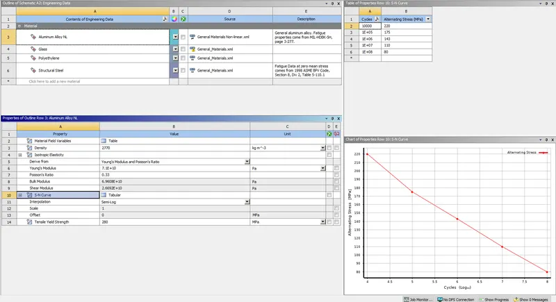
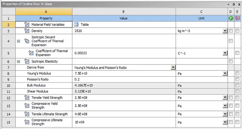
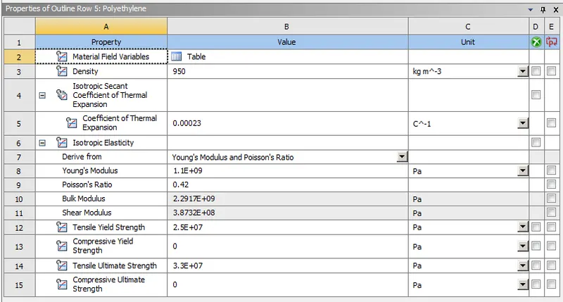
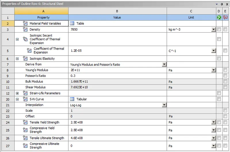
- Import the model provided and check the geometry in the Ansys Spaceclaim for any abnormalities. After importing we'll merge surfaces of the fingers.
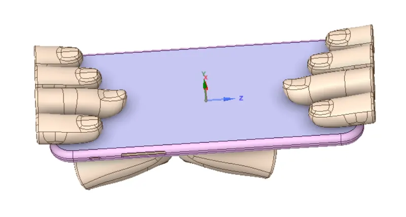
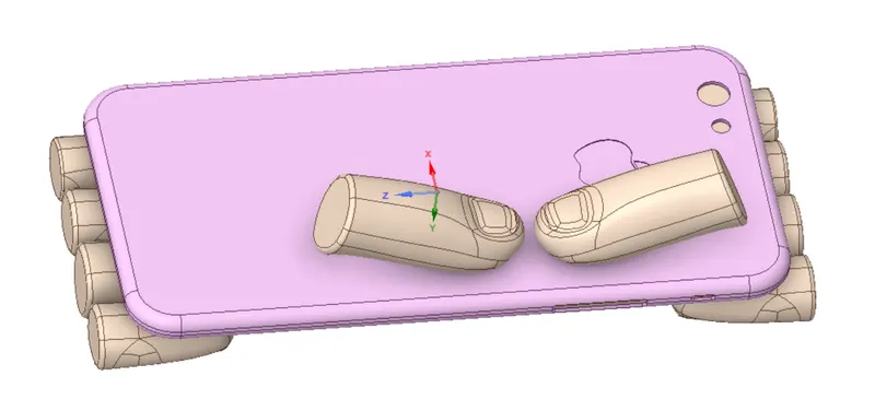
- Now, open Ansys Mechanical and give specific names as(R - Right, L - Left, M - Middle, R- Ring, P- Pointing, S - Small) to the components as shown below:
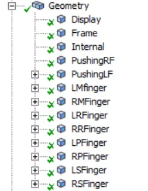
- After giving names, rename them by based on their definition and assign materials as glass to the display, polyethylene to the internal dummy component, aluuminium non linear to the frame, and structural steel to all the fingers.
- Create contact Points and Joints. Let all the contact points be frictionless and bonded for three cases, create body to ground - fixed and translation joints as shown below. Let all the fingers be rigid except for thr right pushing finger.
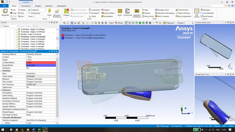
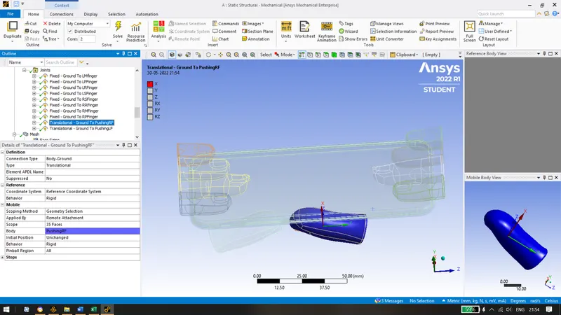
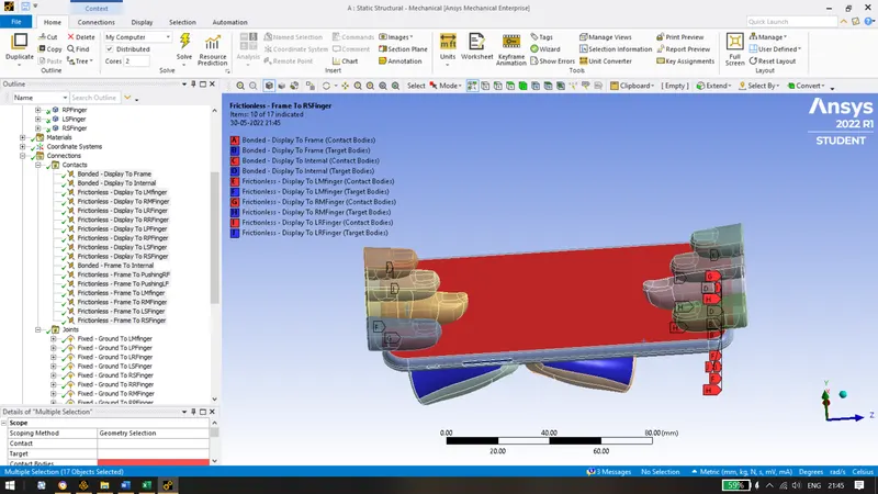
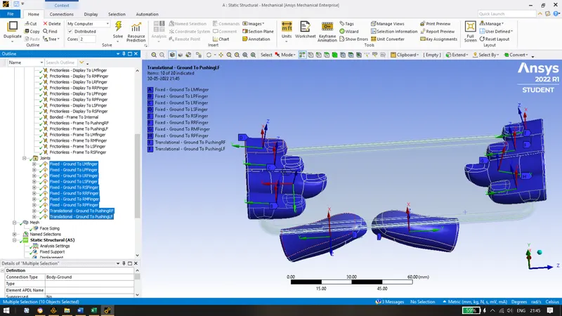
Following contact points and joints have been obtained:
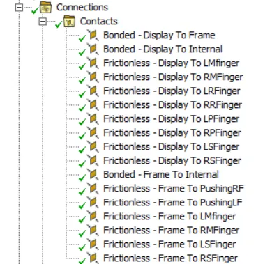
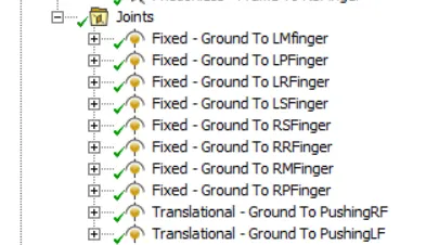
- Mesh all the components with default element size. And refine mesh on the faces which are coming in contact for our study using sizing of 4mm.
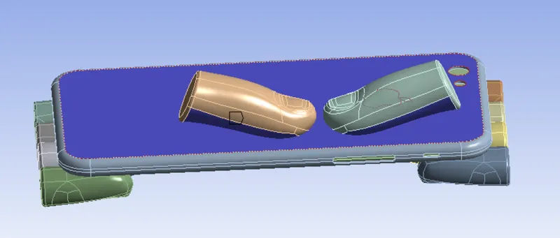
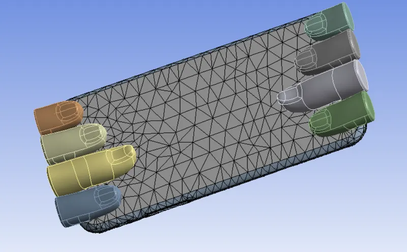
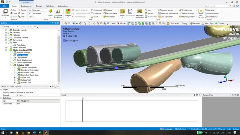
- Apply Fixed support to the internal dummy material on both sides as shown.
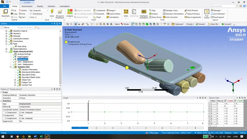
- Allowing the displacement in Y direction only and restricting the other two directions so that we record the deformation in Y direction.
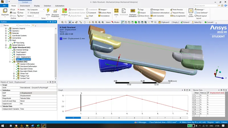
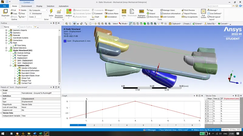
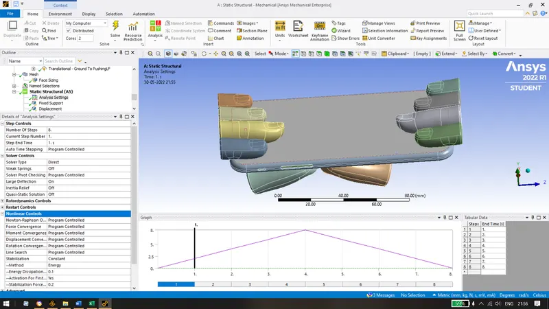
- Apply a joint displacement of 8mm in the x direction for both fingers using tabular data for 8 steps.
- Following analysis settings have been set for the simulation:
- Insert Directional deformation, equivalent stress, contact tool for pressure, fatigue tool for life, stress tool for safety factor, equivalent elastic strain and equivalent stress for the frame.
- Finally following solutions have been obtained after running the simulation for the aluminium frame of the iphone.
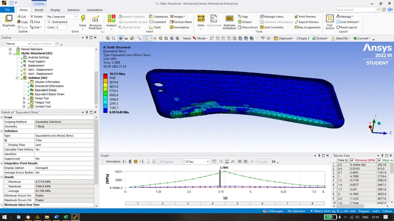
Max stress of 10311 MPa was obtained.
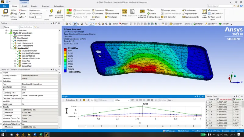
Directional Deformation of 7.9354mm was obtained.
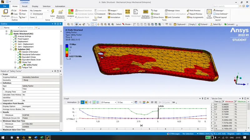
Safety Factor of 0.02715 was obtained.
Maximum cycles of 10^8 was obtained.
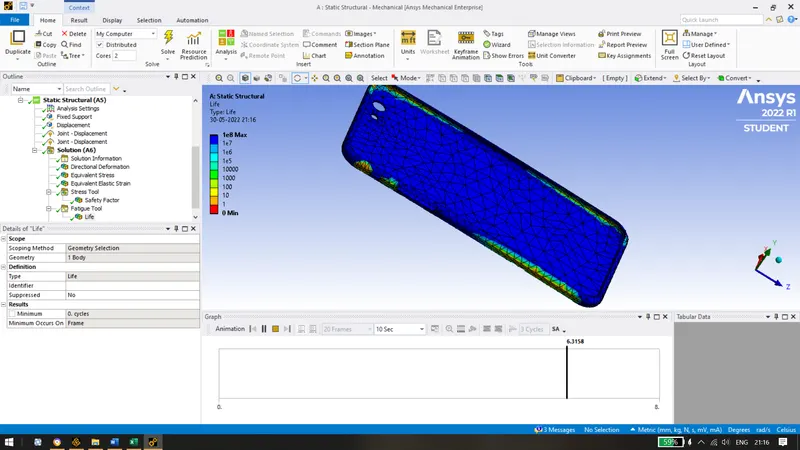
Now for Case 2:
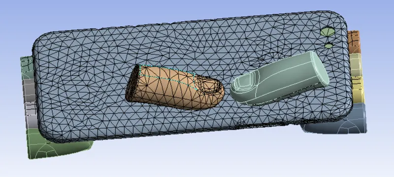
Change the location of thumb fingers at x=22.5mm and z=10mm as given in the challenge. We can do it by moving the component.
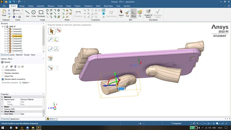
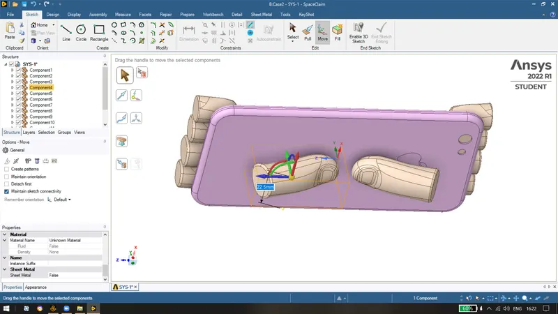
Finally we obtain the model as:
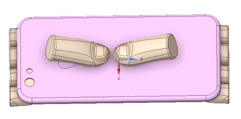
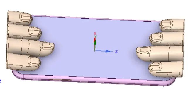
- After following the same procedure as given above, the following solutions have been obtained:
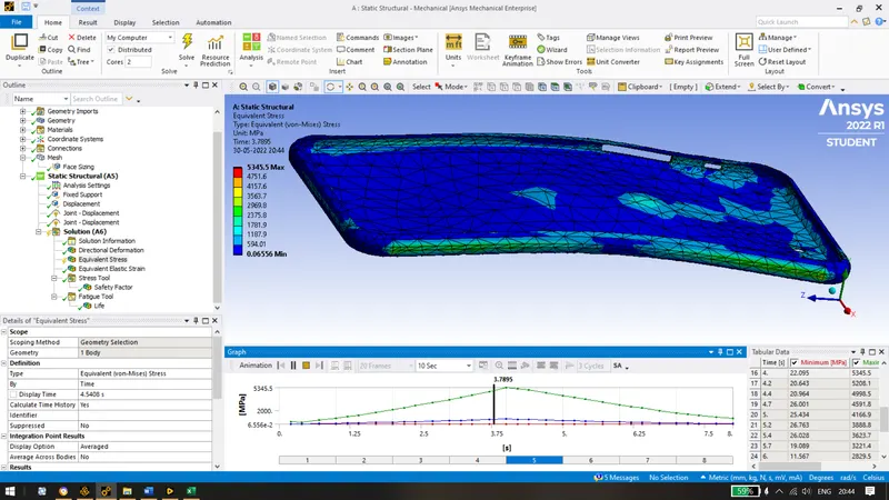
Max stress of 5345.5 MPa was obtained.
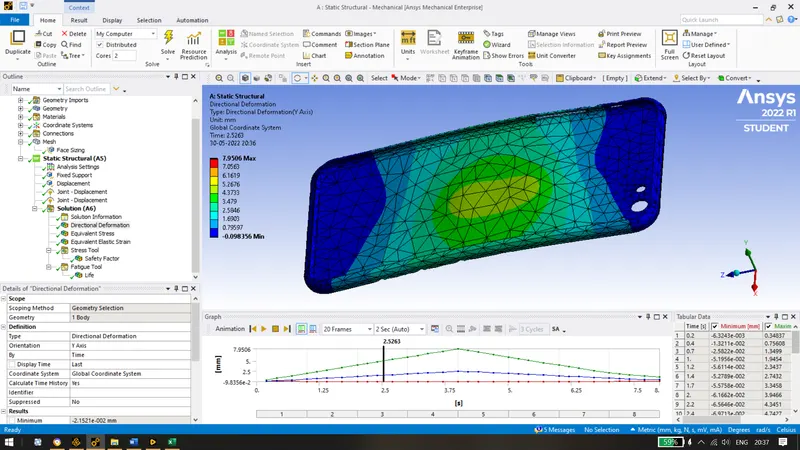
Directional Deformation of 7.95mm was obtained.
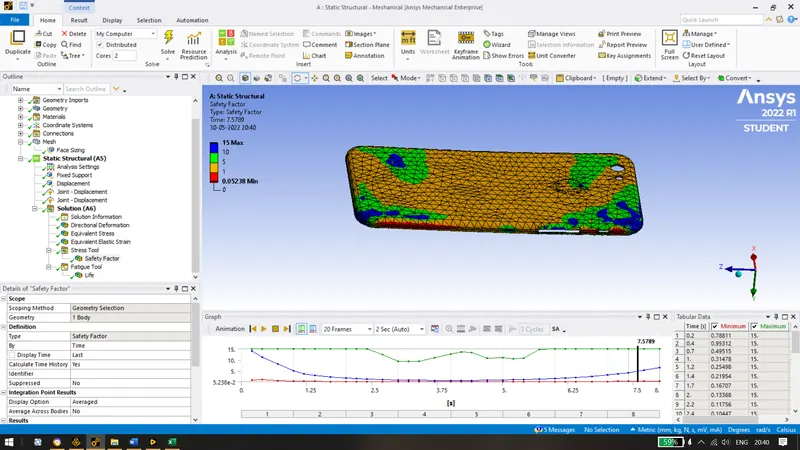
Safety Factor of 0.05238 was obtained.
Maximum cycles of 10^8 was obtained.
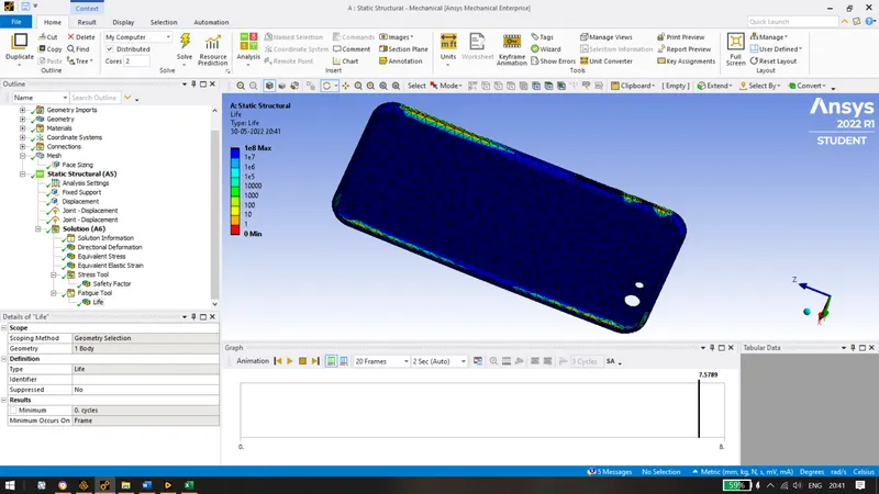
Conclusion: Below, we can see that the stress on the aluminium frame in case 2 is almost the half of the case 1 because the force was applied in the centre of the phone. Due to this the load was well distributed on the entire aluminium frame resulting in low stress. The deformation caused on the frame was almost the same. The minimum factor of safety was obtained in case 1 which depicts that the case 1 can cause more damage to the frame. Also, the same number of life cycles were obtained for both cases.
