Week 5 Bending of iPhone
Aim : To simulate the bending of iPhone.
Objectives :
-
Case 1: Simulate the model as it is.
-
Case 2: Move the bottom fingers from their defined position to the given position X= 22.5mm & Z= 10mm and obtain the results for the simulation.
-
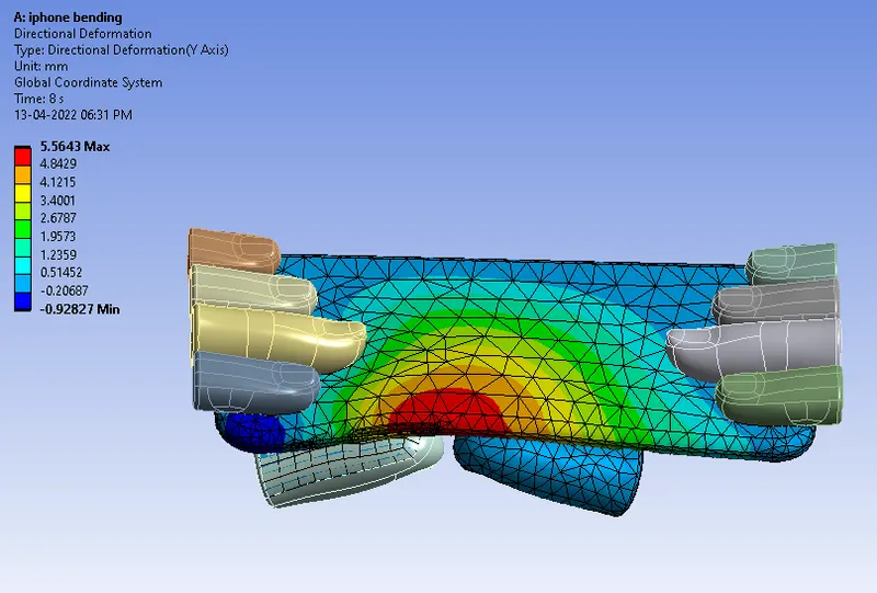
Obtain the directional deformation for the model.
-
Factor of safety of Aluminium Alloy NL.
-
Life of the Aluminium alloy for the case
-
Compare the results and present with the conclusion.
Procedure :
Engineering data and material :
- Open engineering data.
- Go to general non linear material from engineering data sources.
- Add Aluminium Alloy NL to library.
- Go to general materials.
- Add Polyethylene, Structural steel.
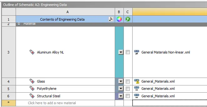
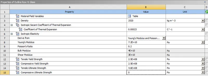
- Duplicate Polyethylene name it as Glass and give following parameter values.
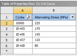
- Go to Engineering Data and select the Aluminium Alloy NL.
- Create the S-N curve as following for the Aluminium alloy NL.
Geometry :
- Import geometry.
- Check for abnormalities.
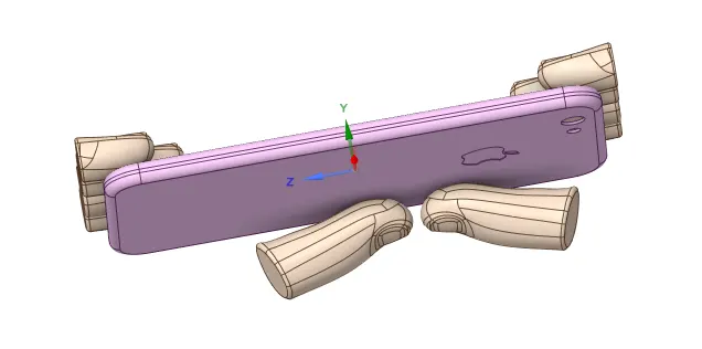
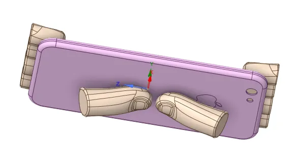
- For Case 2, go to spaceclaim geometry use the move option.
- Now the position of the pushing fingers is changed in the spaceclaim geometry to the given position X=22.5mm, Z=10mm.
Model Setup :
- Open geometry and rename the components as following,
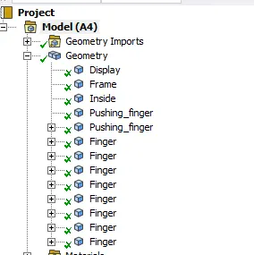
- Assign materials to each components.
Display = Glass
Frame = Alumunium Alloy NL
Inside = Polyethylene
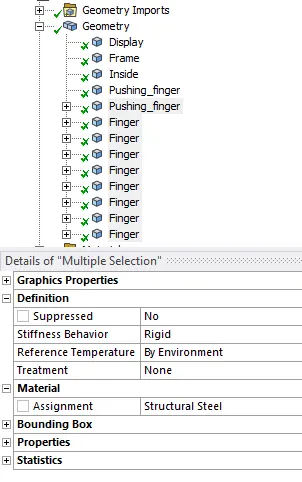
Pushing fingers and fingers = Structural steel
- Select all fingers and one pushing finger and make stiffness behavior as Rigid.
Contacts :
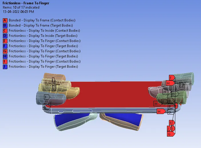
- Delete unwanted contacts.
- Select all contacts and rename based on defination.
- Select contact as bonded for Display to Frame.
- Define Other contacts as frictionless.
Joints :
- Define fixed joint for Fingers.
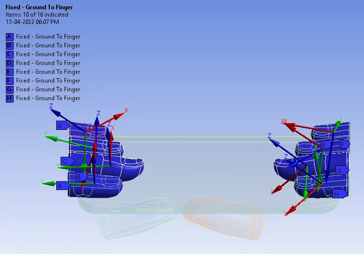
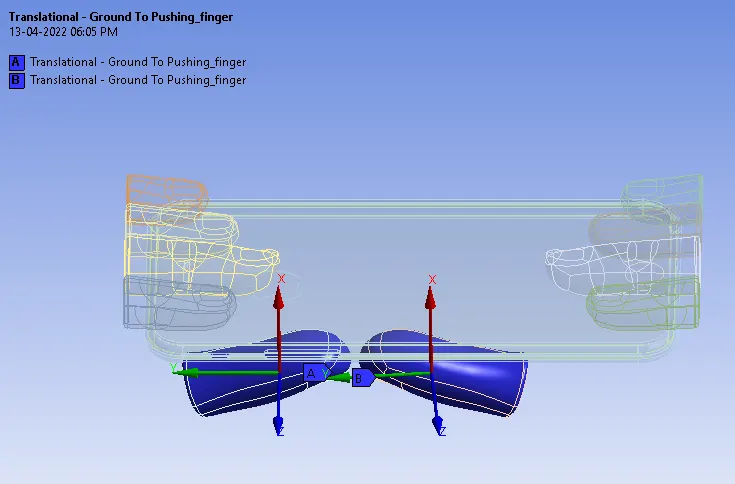
- Define translational joint for Push fingers.
- Reference coordinate system for both should be in same direction i.e. X-axis.
Meshing :
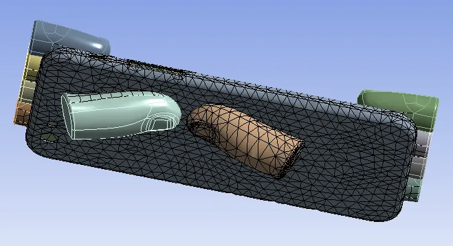
- Insert sizing for frame and push finger contact surface.
- Give element size as 4 mm.
- Generate mesh.
Analysis Setting :
Fixed support :
- Insert fixed support for Inside body.
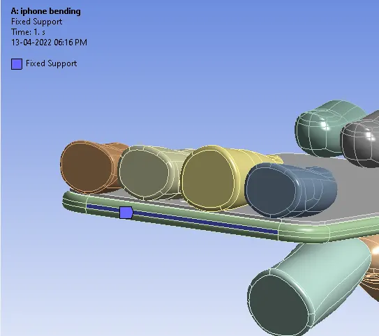
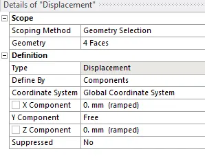
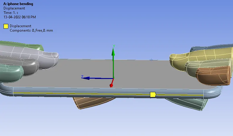
Displacement :
- Insert displacement for frame to constrain the motion in X and Z direction.
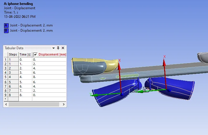
Joint load :
- Insert joint load and give displacement for both Push fingers.
Solution :
Create output results for :
- Directional deformation for model.
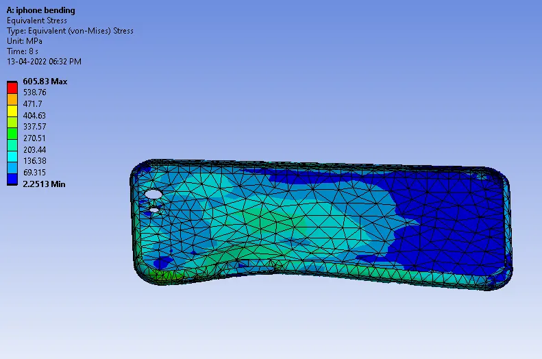
- Equivalent stress on Frame.
- Equivalent strain on Frame.
- Fatigue tool for Life and Safety factor of Frame.
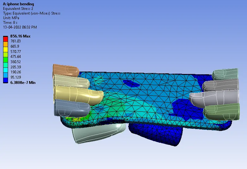
- Equivalent stress for Model.
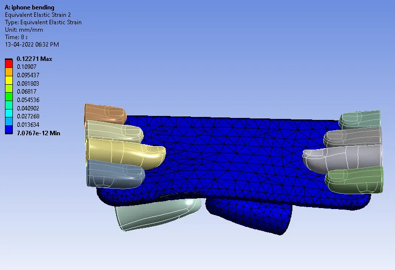
- Equivalent strain for Model.
Results :
Case 1 : Simulate the model as it is without changing push fingers position.
Directional deformation for model :
Equivalent stress for Model :
Equivalent strain for Model :
Equivalent stress on Frame :
Equivalent strain on Frame :
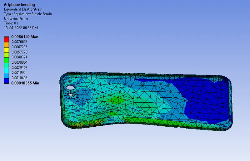
Life of Aluminium Alloy NL :
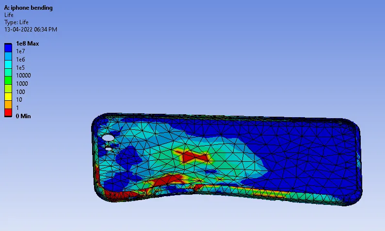
Safety factor of Aluminium Alloy NL :
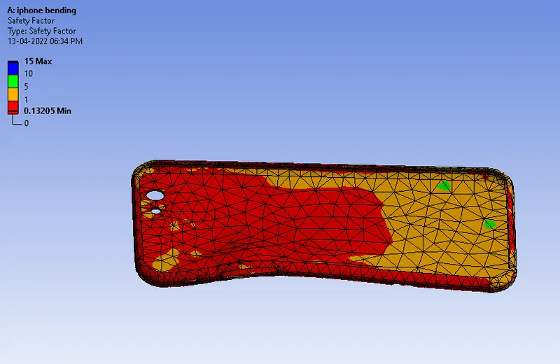
Case 2 : Move the bottom fingers from their defined position to the given position X= 22.5 mm & Z= 10 mm.
Directional deformation for model :
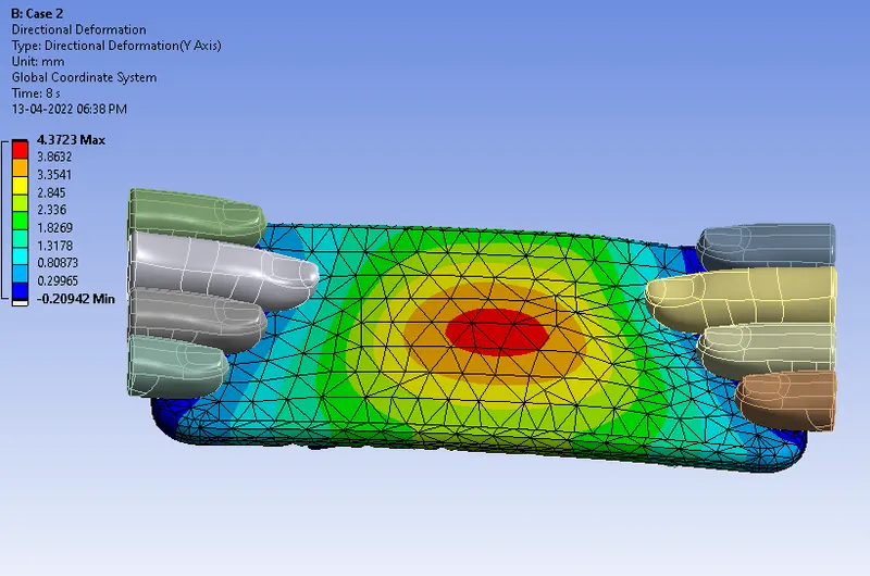
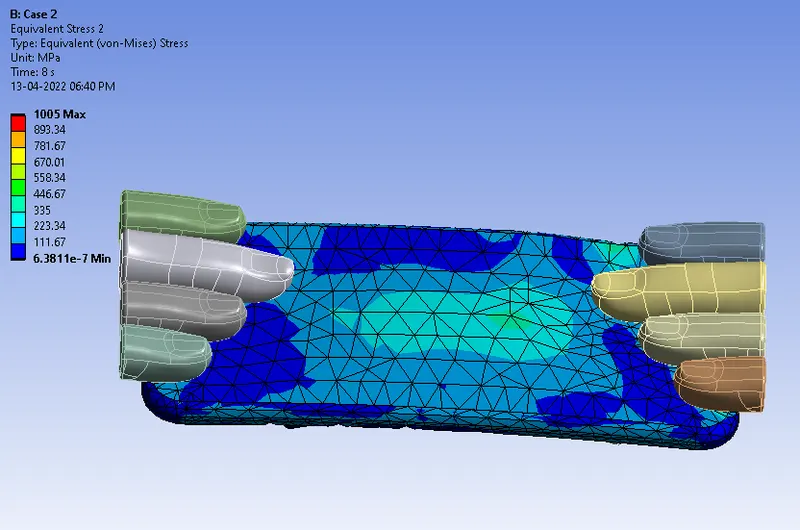
Equivalent stress for Model :
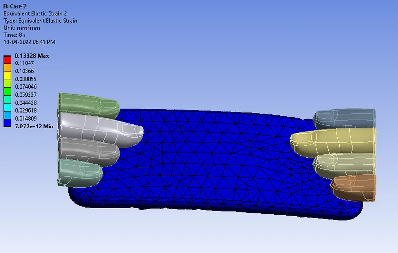
Equivalent strain for Model :
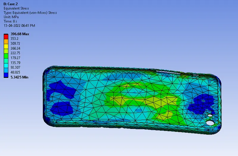
Equivalent stress on Frame :
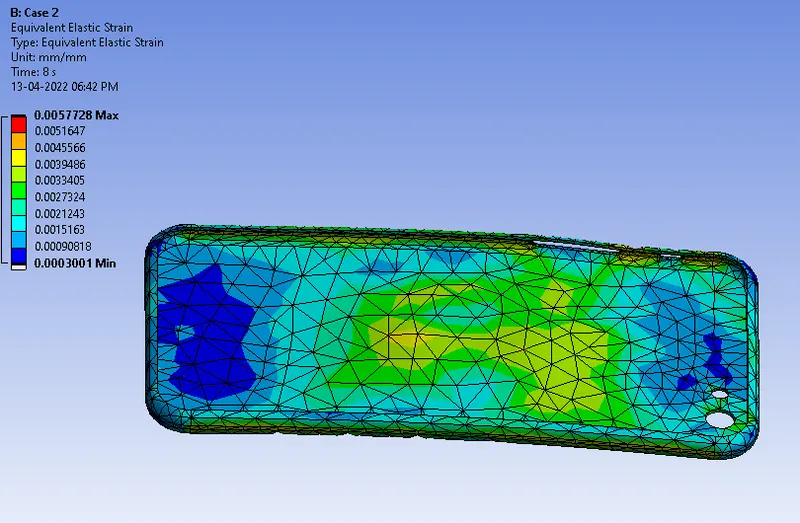
Equivalent strain on Frame :
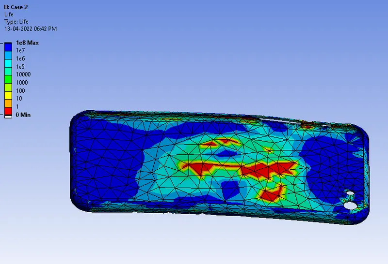
Life of Aluminium Alloy NL :
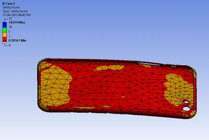
Safety factor of Aluminium Alloy NL :
Comparison of Results :
| Sr. No. | Results | Case 1 | Case 2 |
| 1 | Maximum Directional deformation for model (mm) | 5.5643 | 4.3723 |
| 2 | Minimum Directional deformation for model (mm) | -0.9282 | -0.2094 |
| 3 | Maximum Equivalent stress for Model (MPa) | 856.16 | 1005 |
| 4 | Minimum Equivalent stress for Model (MPa) | 6.3808 E-7 | 6.3811 E-7 |
| 5 | Maximum Equivalent strain for Model | 0.1227 | 0.1322 |
| 6 | Minimum Equivalent strain for Model | 7.0767 E-12 | 7.077 E-12 |
| 7 | Maximum Equivalent stress on Frame (MPa) | 605.83 | 396.68 |
| 8 | Minimum Equivalent stress on Frame (MPa) | 2.2513 | 5.3425 |
| 9 | Maximum Equivalent strain on Frame | 0.008614 | 0.00572 |
| 10 | Minimum Equivalent strain on Frame | 0.000103 | 0.00030 |
| 11 | Maximum Life of Aluminium Alloy NL | 1 E+08 | 1 E+08 |
| 12 | Minimum Life of Aluminium Alloy NL | 0 | 0 |
| 13 | Maximum Safety factor of Aluminium Alloy NL | 15 | 14.974 |
| 14 | Minimum Safety factor of Aluminium Alloy NL | 0.1320 | 0.2016 |
Conclusion :
- By observing the above results Case 2 gives the best results of directional deformation and equivalent elastic strain.
- We can conclude that Case 2 can make the model survive comparing to the Case 1 as the stress and strain developed were comparitively low.