Week 5 Battery characteristics using drive cycle
- 1) AIM
- Simulate generic battery model charge-discharge using UDDS data.
- 2) Objective
- Create the battery model (generic) and analyze the charge-discharge characteristics
- 3) Theory and Blocks used:
- a) Drive cycle:
- A driving cycle is a series of data points representing the speed of a vehicle versus time. Driving cycles are produced by different countries and organizations to assess the performance of vehicles in various ways, as for instance fuel consumption, electric vehicle autonomy, and polluting emissions.
- b) Blocks used:
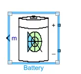
- 1) Generic battery model: Implements a generic battery model for most popular battery types. Temperature and aging (due to cycling) effects can be specified for Lithium-Ion battery type.
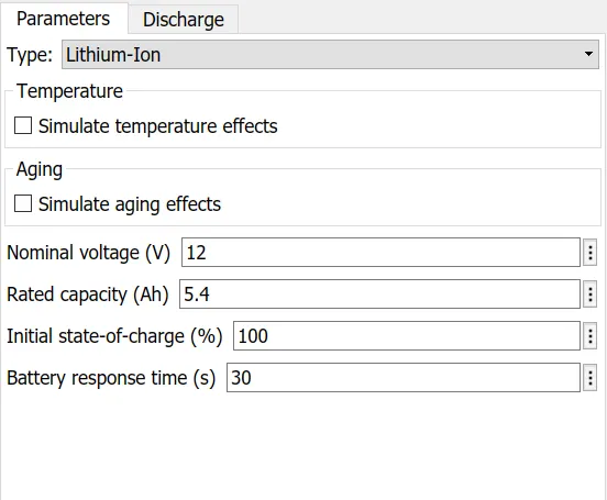
- Block parameters:
- 2) Signal builder
- The Signal Builder block allows you to create interchangeable groups of piecewise linear signal sources and use them in a model. The speed vs time data at various points which forms the udds drive cycle cannot be used as input hence the current profile is imported into signal builder block.
- The udds cycle data in form of current and time in loaded into matlab workspace. Then by using below command two column vectors are created.
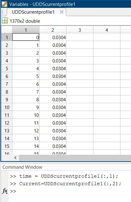
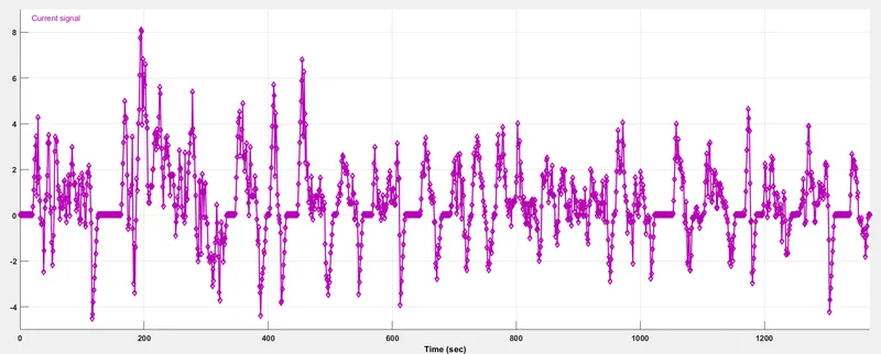
- The custom signal is made as input. The time is set as 1370 s and the current is defined as y value as below
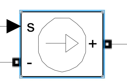
- 3) Controlled current source
-
Converts the Simulink input signal into an equivalent current source. The generated current is driven by the input signal of the block.
- 4) Bus selector
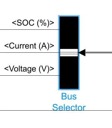
- The battery output is given to bus selector to take different signals to be displayed on scope. This block accepts a bus as input which can be created from a Bus Creator, Bus Selector or a block that defines its output using a bus object. The left listbox shows the signals in the input bus. Use the Select button to select the output signals. The right listbox shows the selections. Use the Up, Down, or Remove button to reorder the selections. Check 'Output as virtual bus' to output a single bus signal.
-
- 5) Power GUI continuous block
- For the simulation of any simscape block in the interface the block is necessary
- 4) Simulink Model,Results and Inference
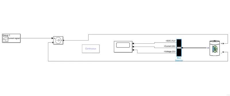
- The model is simulated for 1370 s
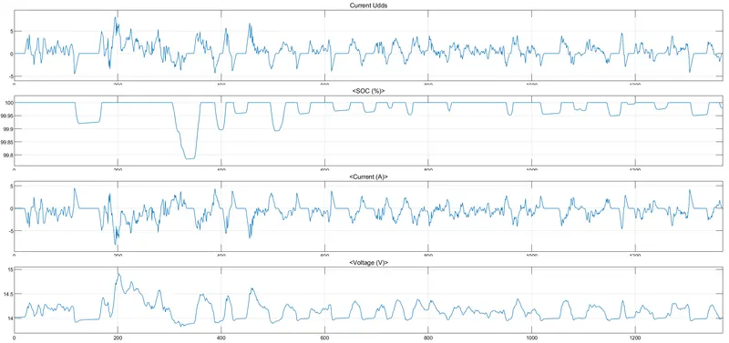
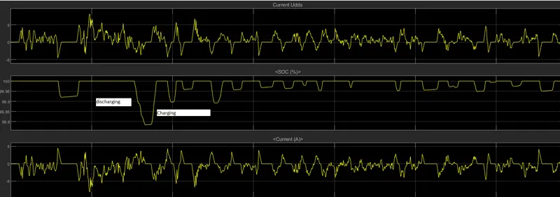
- A negative current indicates charging whereas a positive current indicates a discharge from the battery. The SoC at the end of the cycle is about 99.9 indicating that during the drive cycle there is regeneration happening to a large extent. This can be interpreted from the current in a negative direction indicating charging of the battery. The driving pattern for most of the cycle is in such a way that vehicle accelerates drawing a current from the battery then de-acceleration ( regeneration of the same amount) then constant speed.