Week 5 Battery characteristics using drive cycle
AIM : To simulate generic battery model charge discharge using UDDS data.
SOLUTION :
A drive cycle is a series of data points representing speed vs time. They are used to study about the performance of the vehicles, fuel consumption and economy.
Generic battery models are popular types of rechargeable batteries.
The blocks used to simulate generic type are from workspace,controlled current source,generic battery,bus selector,scopes &powergui.
From workspace: Used to import data from matlab workspace and reads data.
Controlled current source: The Controlled Current Source block converts the Simulink input signal into an equivalent current source. The generated current is driven by the input signal of the block.
Generic battery: Rechargeable batteries.
The fig1 below shows the equivalent circuit that the block models.
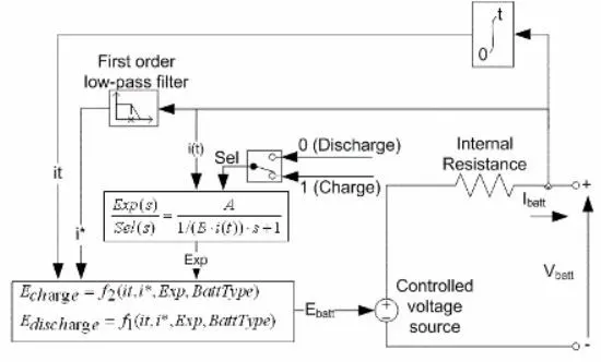
fig1
Bus selector: he Bus Selector block outputs the elements which we select from the input bus and the block can output the selected elements separately or in a new virtual bus.
Scope: Displays signal generated during simulation.
Powergui: Used to simulate any Simulink model containing Simscape Electrical Specialized Power Systems blocks. It stores the equivalent Simulink circuit that represents the state-space equations of the model.
SIMULATION AND RESULT:
The images attached below represents generic battery model charge discharge using UDDS data.
The drive cycle data is imported into matlab. It is given in from workspace block.
The battery settings are kept in default condition.
Stop time is set as 1370 sec after connecting the blocks together.
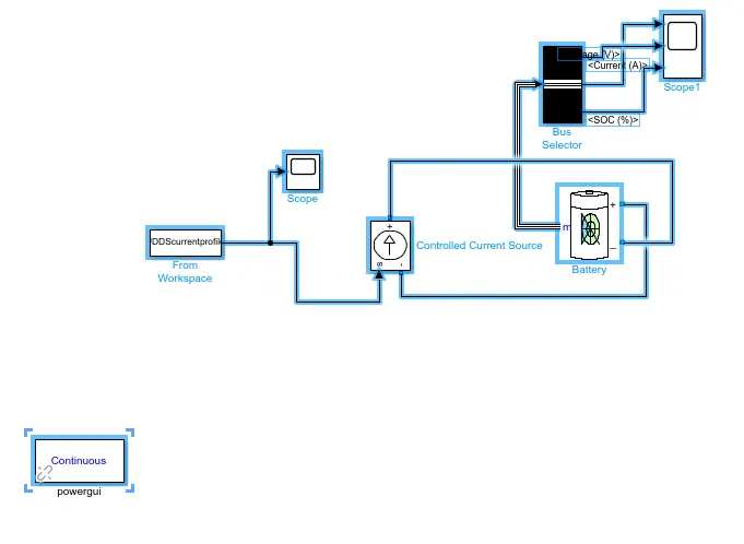
fig2
The image given below represents the change in voltage and current with respect to drive cycle.
When system accelerates, there is a positive current that flows from battery to load. Increase in speed causes an increase in power thus we require a higher voltage and current. This is observed in the graph.
When the braking condition or deceleration occurs, the current changes its direction and flows to the battery source (i.e from load to source) . This causes charging and former condition denotes discharging.
SOC represents state of charge. There is a general reduction in SOC as discharge keeps taking place to provide neccesary power through electrical load. When charging takes place SOC increases a bit.
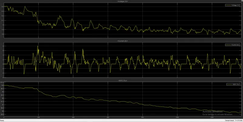
fig3
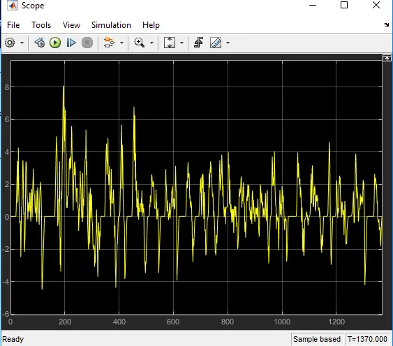
fig4
(Drive cycle data for total time,1370 sec)