Week 5 Battery characteristics using drive cycle
AIM:
Simulate generic battery model charge discharge using UDDS data.
THEORY:
What is generic battery model?
This battery block represents most popular types of rechargeable batteries. This block is used to analyse charge/discharge characteristics, SOC, and temperature effects and age equivalent of the battery system. The parameters can be extracted from a datasheet provided by the manufacturers to give it to the battery block.
Here we are using Tenergy 18650 2200mAh Li-Ion cell.
SIMULINK MODEL:
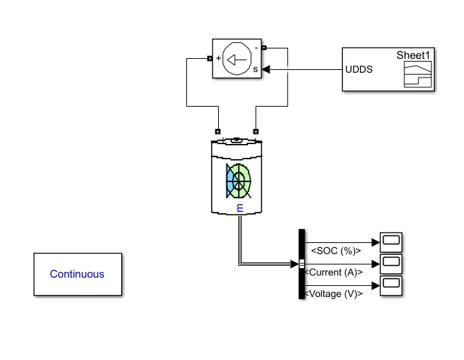
FIG: Generic battery model using UDDS driving cycle
Blocks used:
1.Battery:
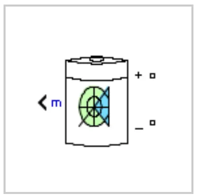
BATTERY SPECIFICATION:
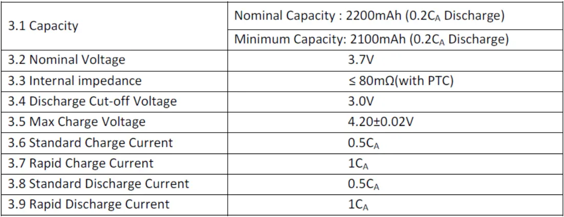
These specification from datasheet is used to configure the model.
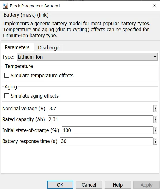
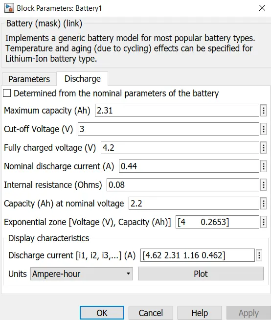
The above figures shows the configuration of battery model.
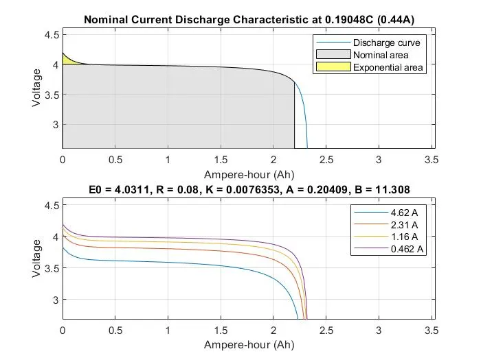
The nominal current discharge characteristics will be:
2. Controlled Current Source:
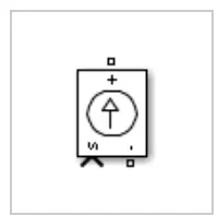
The Controlled Current Source block converts the input signal into an equivalent current source. The generated current is driven by the input signal of the block. Here the input signal comes from the drive cycle. We initialize the Controlled Current Source block as AC current.
3.Signal Builder:
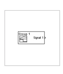
Signal builder is used to crat the drive cycle data of the UDDS cycle. The limitation of the signal builder is that it accepts data in the form of only the current profile. So the sped v/s time data from drive cycle is converted to its corresponding current profile with respect to time.
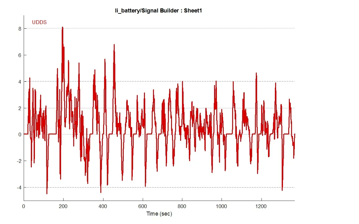
FIG: UDDS cycle in current profile.
4.Bus Selector:
The Bus Selector block outputs the signals you select from the input bus. The block can output the selected elements separately or in a new virtual bus. Here we are outputting the SOC, current, voltage values to a scope.
5.Scope:
Scope helps to display the time domain signals.
6.Power GUI:
Powergui block used to simulate any Simulink model containing Simscape, Electrical Specialized Power Systems blocks. It stores the equivalent Simulink circuit that represents the state-space equations of the model. Here I have choose continuous solver, which uses a variable-step solver from Simulink.
RESULT:
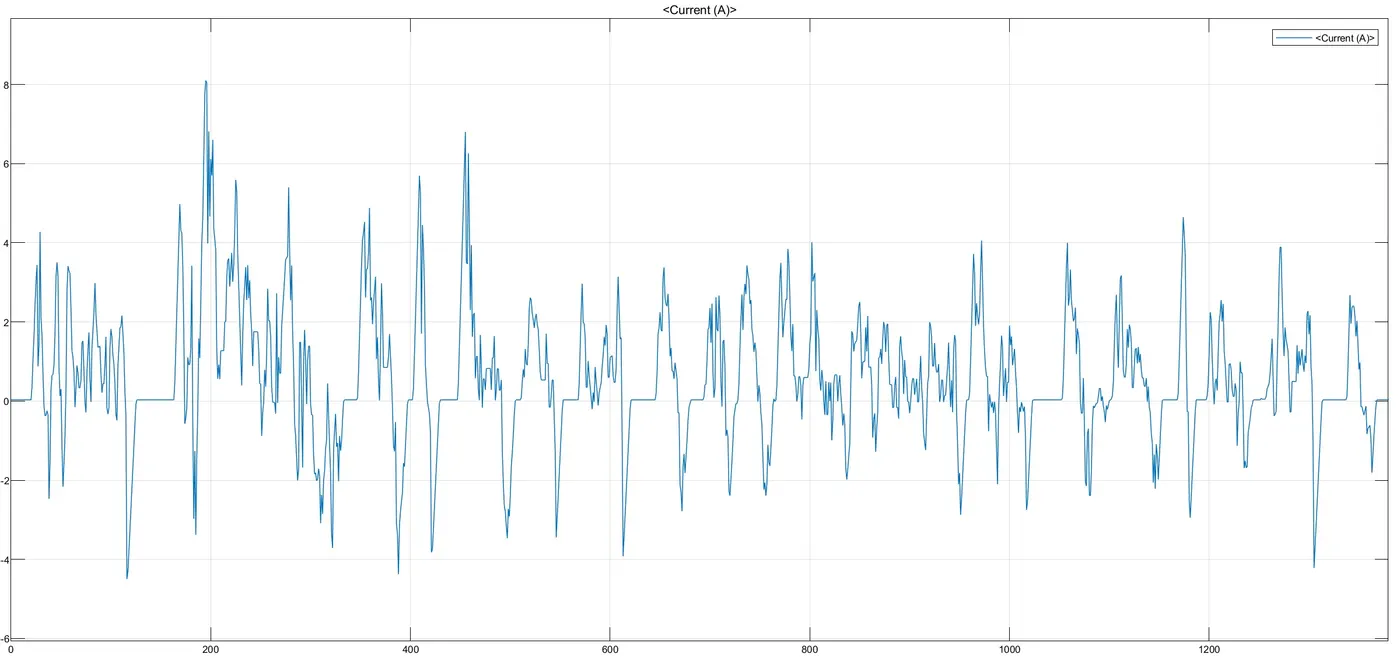
FIG: Current Profile
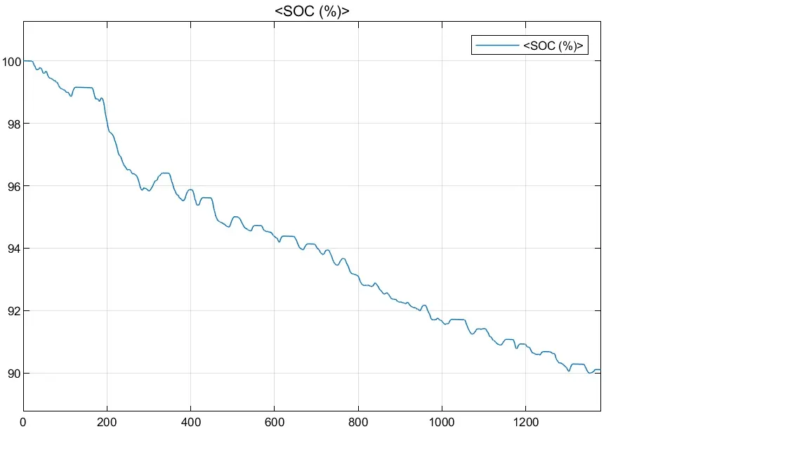
FIG: State of charge
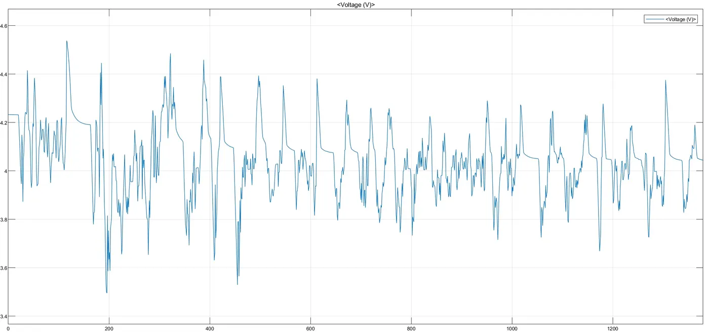
FIG: Voltage profile
From these graphs we can see that battery SOC is becoming up and down according to the charging and discharging of battery. The positive current means discharge of battery and negative current means charging of battery.