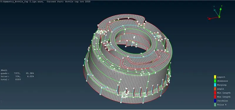
Week - 5 - 2D meshing for Plastic components
AIM:-
To mesh the given plastic component.
Procedures for Meshing a 2D component:-
i) Importing the CAD model into ANSA:-
- The cad model is imported into the Ansa software by clicking File ---> New command.
ii) Geometry Checks:-
- This will help us clear all the surface errors, unwanted cons, and any disruptions placed in the CAD model.
- This can be done by the command Tools ---> Checks ---> Geometry. And errors like cons, unchecked surfaces, cracks, needle faces, etc are shown.
- Some of these errors can be automatically resolved by the ANSA by using the command Right click + Fix in the geometry check dialog box.
- Some of the errors like unchecked faces will be cleared manually using Faces ---> Delete and Faces ---> New commands.
- When all the errors are fixed check it again in geometry checks.
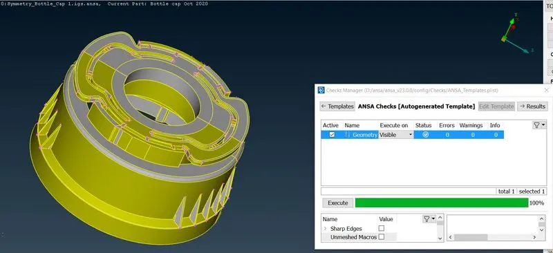
- Once all errors are fixed we can move to mid-surfacing and meshing the given component.
- Before extracting the Mid surface of the components, it is important to measure their thickness. And this can be achieved by using the command Utilities---> Measure.
Meshing:-
here we can use both manual mid surfacing and auto mid if it is possible.
For manual mid-surfacing, we need to use the middle feature to extract mid surface.
- Now we need to provide the quality criteria as provided by using the command Utilities ---> Quality Criteria ( or by clicking F11 ).
- Then switch to the 'Presentation parameters' tab, In the Graphics division put a tick mark for Elements% and choose the Details on demand effect as 'More details'.
- Then choose Utilities ---> Mesh parameters and give the target length as 1.
- Then choose Perimeters ---> Length command, choose the entire component, and give the target length of the mesh value as 1.
- For fixing the errors the following commands are commonly used, Elements ---> Split, Elements ---> Swap, Grids ---> Paste, Elements ---> Join, Shell mesh ---> Reconstruct, and Shell mesh ---> Smooth.
- Then the Midsurface ---> Align manager is used to match the areas and perimeters which came out of their original mid surface.
- Try to keep the tria percentage as low as possible.
- If an error cannot be fixed then we can compromise with the Cad model.
- Atlast set a new PID for the mid surface and provide the required thickness.