Week - 5 - 2D meshing for Plastic components
2D MESHING OF A PLASTIC COMPONENT (Bottle Cap) WITH THE GIVEN QUALITY CRITERIA
Aim : For the given Bottle Cap model, Check the geometrical errors after that take the mid surface for all the surfaces with different thickness and mesh the mid surface with the given element Quality criteria.
Given Quality requirements :
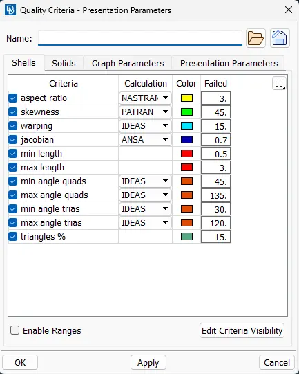
| S.N | Quality Criteria | Value |
| 1 | Aspect Ratio | 3 |
| 2 | Skewness | 45 |
| 3 | Warping | 15 |
| 4 | Jacobian | 0.7 |
| 5 | Min. Length | 0.5 Units |
| 6 | Max. Length | 3 Units |
| 7 | Min angle Quad | 45 |
| 8 | Max angle Quad | 135 |
| 9 | Min angle Tria | 30 |
| 10 | Max angle Tria | 120 |
| 11 | Tria % | 15 |
| 12 | Target Mesh Length | 1 |
Procedure :
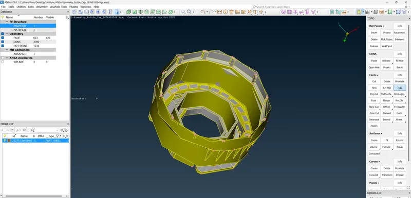
- The Bottle Cap model is opened in the ansa software and the model initially contains only edges of 'single cons' indicating that the individual edges are not connected to their corresponding surfaces as shown in the figure below. The red color on the edges indicates the same.
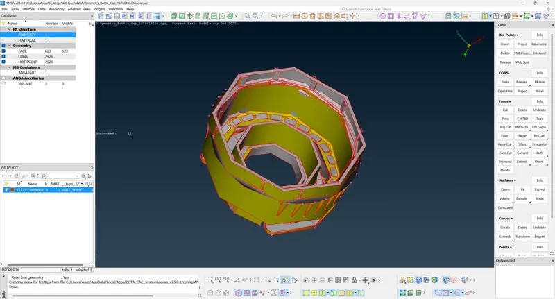
- The 'Topo' option is used and the whole model is selected and by clicking the middle mouse button it connects all the corresponding surfaces making it a 'double cons' edges which is indicated by the color 'yellow'.
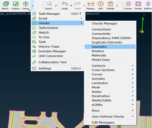
- The whole model has to checked for any geometrical error before the meshing can be started. The whole model is selected and the 'Check' option is clicked and the 'Geometry' option is selected which opens up a geometric check window, where all the required checks are selected and is executed as shown in the below figure.
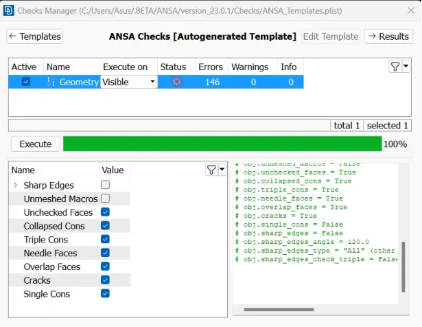
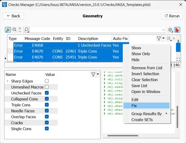
- All the errors obtained are selected simultaneously and with the right click of the mouse the fix option is selected.
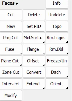
- The errors which are left are corrected manually using the commands like ‘Delete’ and ‘New’ in the Faces window.
- Once the Geometric correction is done, the F11 key is pressed and required Quality criteria is set.
- Similarly the required Mesh parameters are also set.

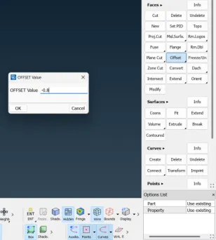
- Since the thickness of the is not constant the Mid surfacing of the component is obtained by measuring the thickness of the various surfaces of the model at different points of a particular surface, then the surface of the model is selected and the ‘Offset’ command is used to specify the distance where the mid surface is to be located. The Midsurface can also be obtained using a 'Middle' command by selecting the opposite and adjacent surfaces.
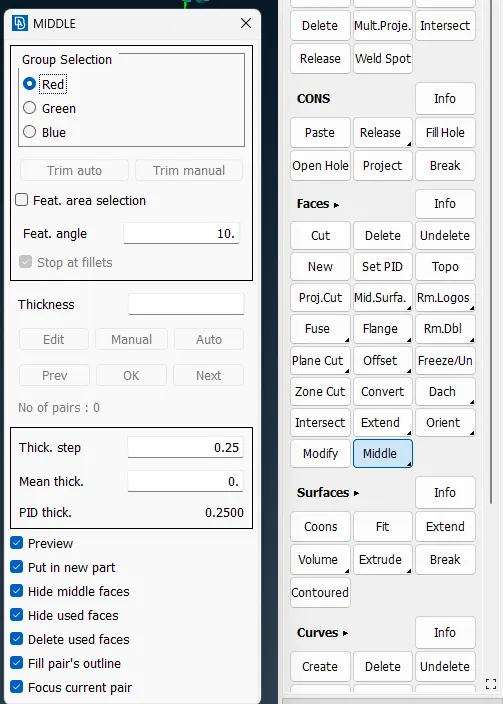
- The New property is set for the Mid surfacing feature and only the mid surface is selected in the property box. Similarly the Mid surface is obtained for surfaces with different thickness. The 'On COG' command is used to determine the axis through which the Mid surface can be copied. The Mid surfaces for Features with same dimensions can be copied using the 'TRANSFORM' command and selecting the COG points which was determined previously.
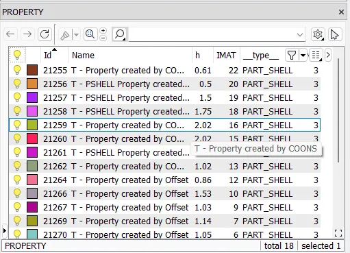
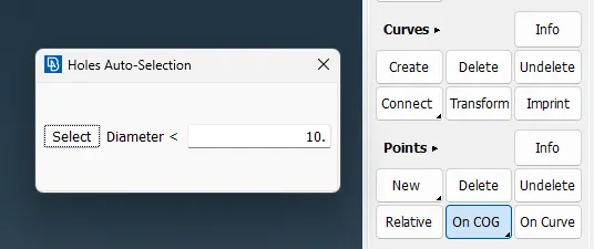
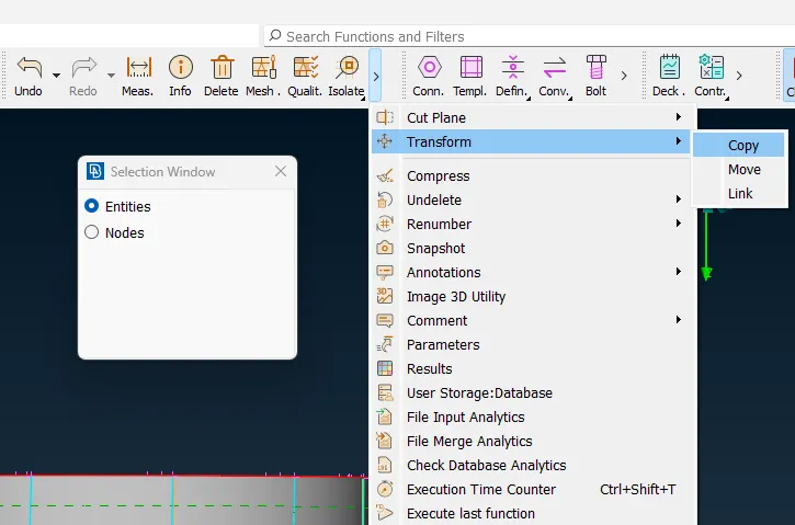
10. The obtained Mid surfaces are joined to the adjacent surfaces using the 'Extend' command. Meshing is done for the Mid surface obtained by selecting the Classic Mesh option and clicking on the ‘Best’ command in the Mesh Generation window.
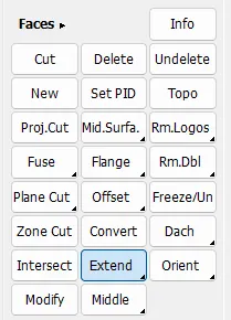
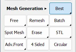
- The whole model is selected and the middle mouse button is clicked to generate mesh.
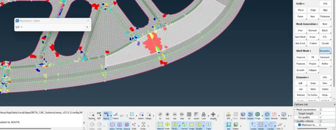
- The Generated Mesh is optimized to meet the Quality criteria using the ‘Reconstruct’, ‘Collapse’ and ‘Smooth’ commands in Shell Mesh window, also the triasare reduced using the ‘Split’ , ‘Join’ and ‘Swap’ commands in Elements window.
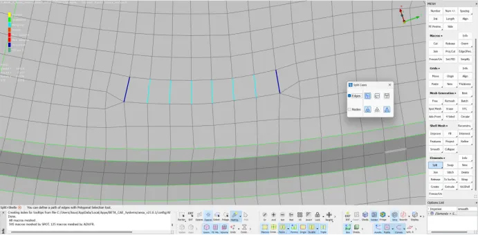
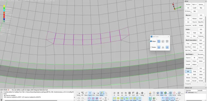
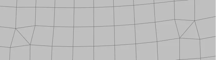
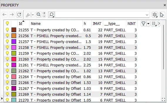
- Once the model optimization is completed and the thickness is assigned to each of the Mid surfaces in the Property window. The Quality criteria window is opened and in the Presentation parameters the ‘Draw shell as solid’ option is checked and is applied on the model.
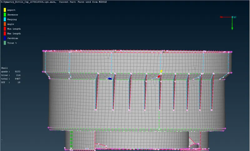
14. The final model will have meet the Quality criteria with the minimum trias with the good mesh flow as shown in the below figure.
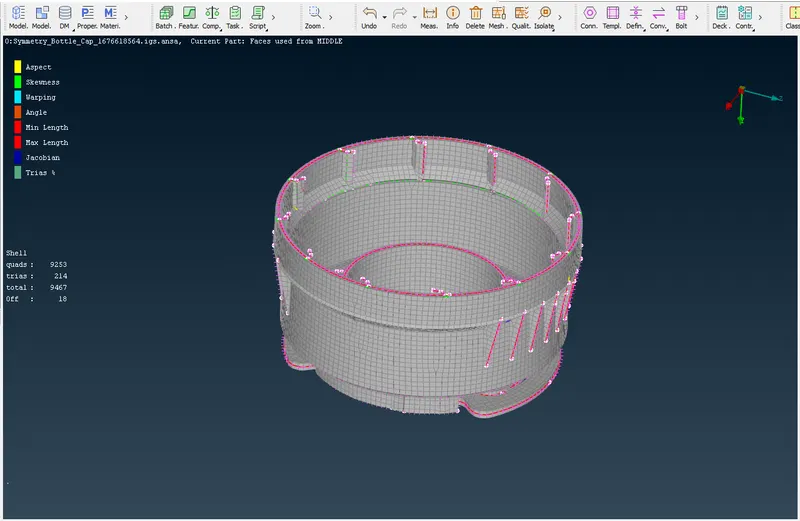
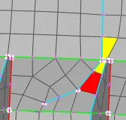
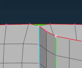
15. The mid surface of the property ID '21259', '21260' and '21274' has features whose thickness is around 0.3 to 0.5mm and it's less than the minimum mesh dimensions of 1 mm. So the quality errors cannot be met with current geometrical dimensions.