Week 4 -Wire Bending Challenge
Understanding the effect of static structural analysis on a wire bending:
AIM:
To study and perform structural analysis on the bending of wire with different material and compare the analytical results. Grid dependency test was also performed to optimize the element size for better accuracy.
Case 1: Copper Alloy NL
Case 2: Aluminium Alloy NL
Case 3: Magnesium Alloy NL
ANALYSIS SETUP FOR BENDING OF WIRE:
I. GEOMETRY:
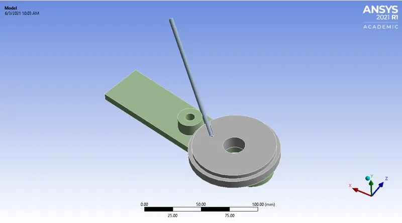
The CAD model of bending of wire is imported in Ansys static structural environment. It comprises of three different components named as wheel, wire and lever. It is based on principle that the wheel would be in fixed position and lever will rotate in clockwise direction that will be in action of bending of wire.
II. MATERIALS:
Below are the materials which is used to perform analysis for the bending of wire. The analysis is carried out for each material individually.
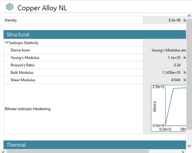
Case 1: Copper Alloy NL (Wire)
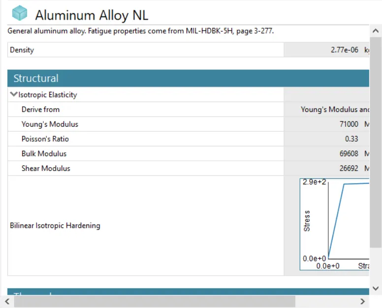
Case 2: Aluminium Alloy NL (Wire)
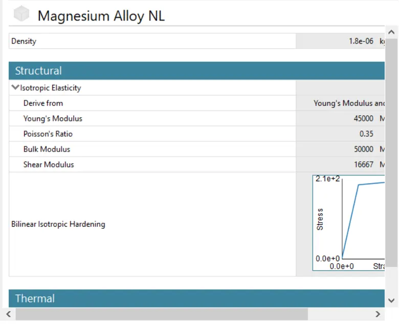
Case 3: Magnesium Alloy NL (Wire)
Case 4: Structural Steel (Wheel and Lever)
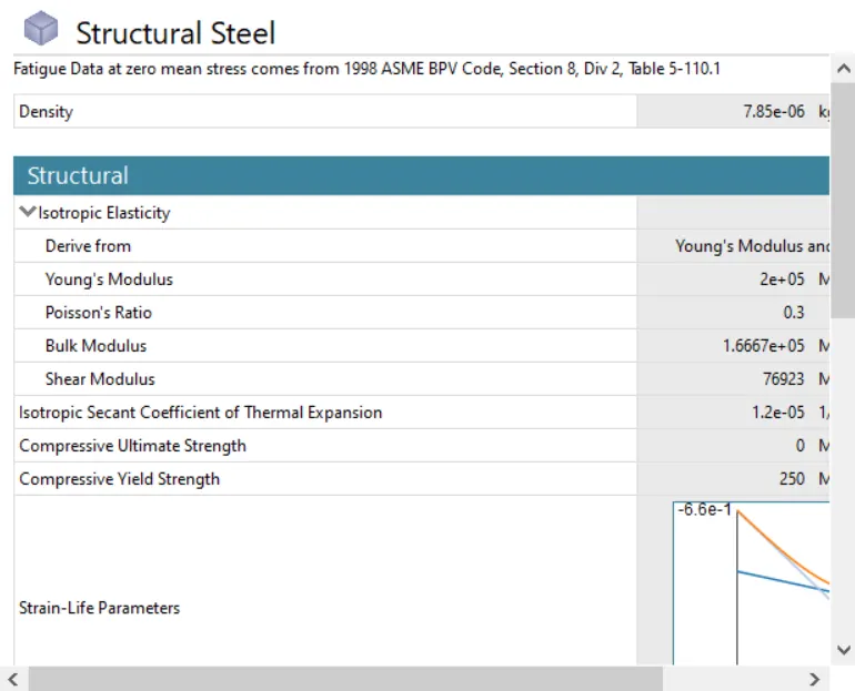
The details of each material has been carried out below as shown in the image:
III. CONNECTION DETAILS:
A. CONTACT DETAILS:
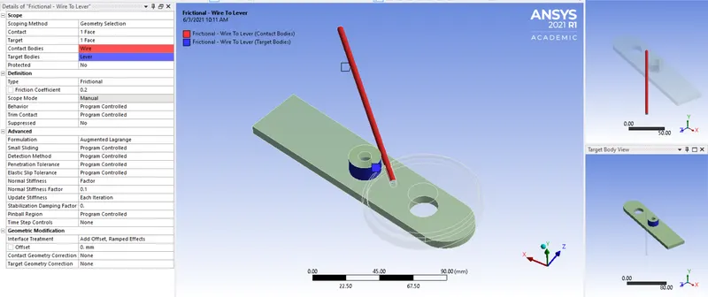
1. Frictional- Wire and Lever:
Frictional contact is given below between faces of wire and lever as shown in the image below. The 1 face of wire came in contact with 1 face of lever with a frictional coefficient of 0.2. Then the behaviour of geometry is changed to Program controlled and then the formulation is changed to Augmented Lagrange. Also, normal stiffness factor of 0.1 is assigned to the contact faces. Then make the update stiffness as 'Each Iteration.' Lastly, interface treatment in geometric modification is assigned as 'Add offset, Ramped effects.'
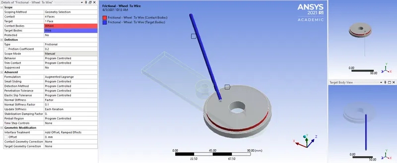
2. Frictional- Wire and Lever:
Frictional contact is given below between faces of wheel and wire as shown in the image below. The 4 faces of wheel came in contact with 1 face of wire with a frictional coefficient of 0.2. Then the behaviour of geometry is changed to Program controlled and then the formulation is changed to Augmented Lagrange. Also, normal stiffness factor of 0.1 is assigned to the contact faces. Then make the update stiffness as 'Each Iteration.' Lastly, interface treatment in geometric modification is assigned as 'Add offset, Ramped effects.'
B. JOINT DETAILS:
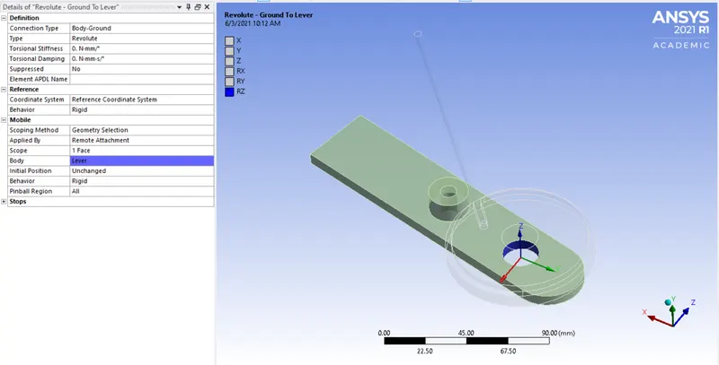
Revolute-Ground to Lever:
In this joint, we have to select the lever as geometry selection part. Then we have to change the connection type and connection as 'Body-ground' and 'Revolute'. After that we have to select the reference coordinate system as Z-axis.
IV. MESH:
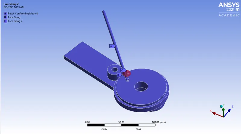
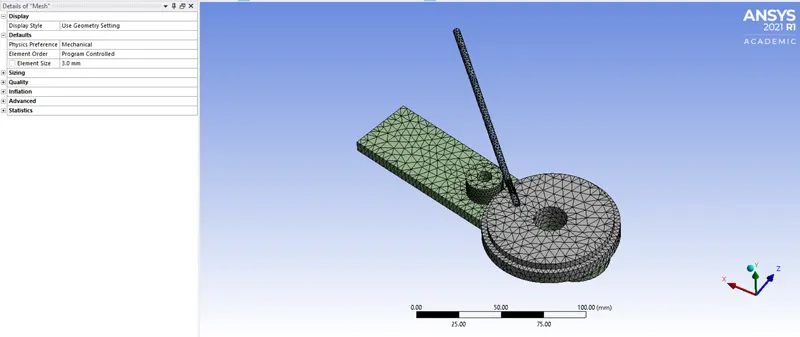
- Basically, we have performed patch conforming method as we have three bodies for the geometric selection.
- As, we have to do face sizing for the critical part, hence we have selected 4 faces as critical part and given element size as 1.2 mm.
- Again, at some part we want more finer mesh, so that it will not break at time of bend, that's why we have chosen the type as sphere of influence with a radius of 7 mm and element size of 0.8 mm.
- Likethat, we have generated the fine mesh which is sufficient to carrry out simulation which gives desired results.
V. BOUNDARY CONDITIONS AND ANALYSIS SETTINGS:
A. ANALYSIS SETTINGS:
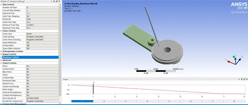
For this analysis the number of steps is set to 10 with Auto Time stepping is ON and it is defined by time. Then, for the first step the initial time step it is to be decided as 0.1 s, likewise maximum and minimum time step is to be 0.2 and 0.01 s respectively. After that, the solver type is to be Direct and then Large deflection is set to On, so as to account for change in stiffness due to change in shape of gears. When stabilizers are activated, it add dampers to all nodes. When the large displacement nodes try to move the force is added to balance them thus favoring convergence. Hence, the energy dissipiation is said to be 0.1.
B. BOUNDARY CONDITIONS:
1. Fixed Support:
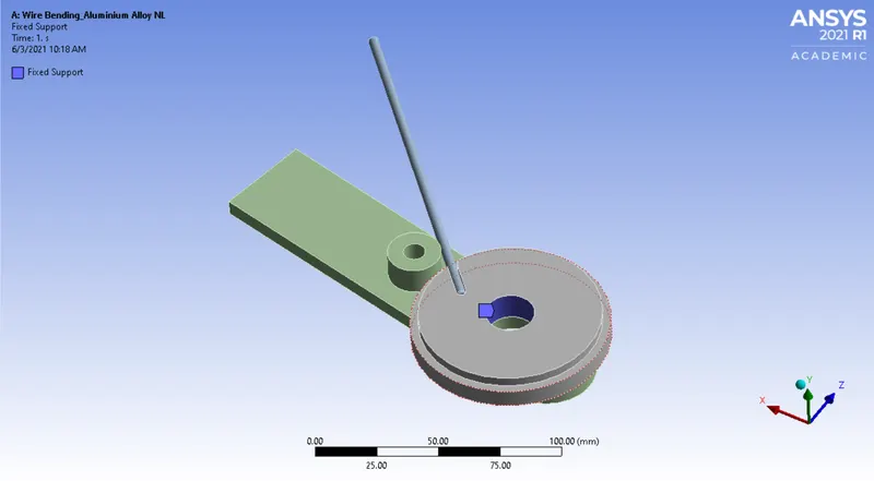
Basically, we have to fix the part so to analyze the results. Therefore, we have fixed the wheel as its geometric selection and we have selected it as fixed type support.
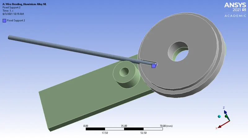
2. Fixed 2 Support:
Basically, we have to fix the part so to analyze the results. Therefore, we have fixed the front face of wire so it will not slip while bending as its geometric selection and we have selected it as fixed type support.
3. Joint-Rotation:
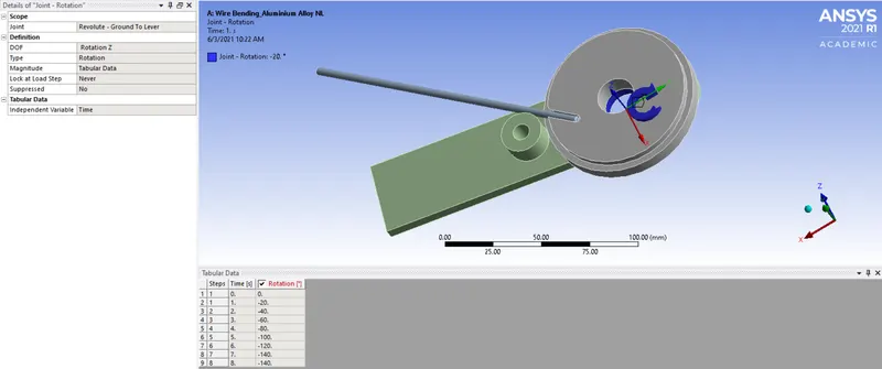
Lastly, we have selected revolute joint as ground-lever. Then, we have taken DOF and its type as 'Rotation Z' and 'Rotation'. Likewise, the lever joint is given a rotation of about 140 degrees such that wire bends around the wheel.
VI. POST-PROCESSING RESULTS:
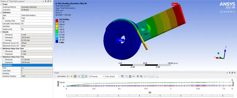
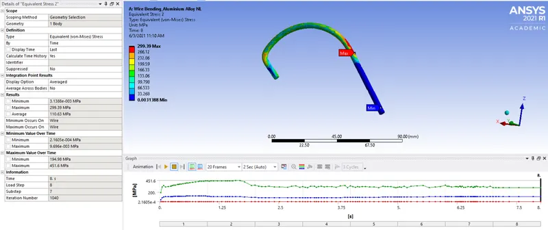
Now, we have to compare the deformation and stress on the basis of different materials. Then, we have to analyze the result for total deformation, equivalent stress and strain for wire. The results are as shown below:
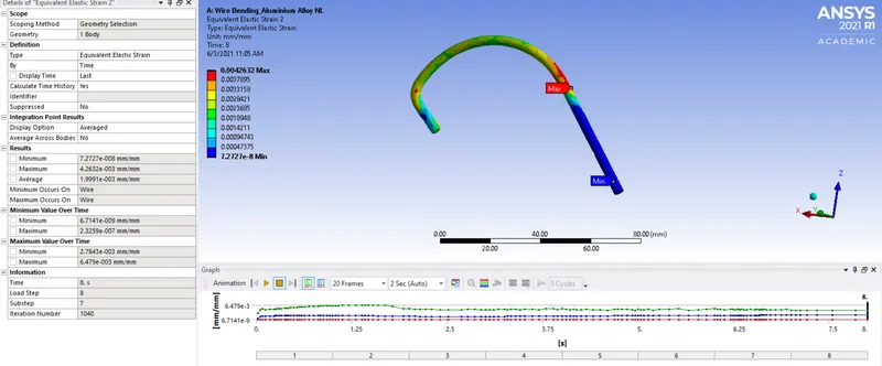
Case 1: Aluminium Alloy NL
I. TOTAL DEFORMATION:
II. EQUIVALENT STRESS FOR WIRE:
III. EQUIVALENT STRAIN FOR WIRE:
Case 2: Magnesium Alloy NL
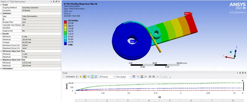
I. TOTAL DEFORMATION:
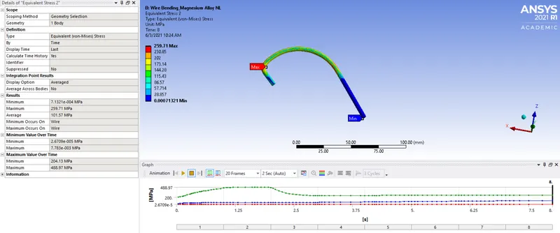
II. EQUIVALENT STRESS FOR WIRE:
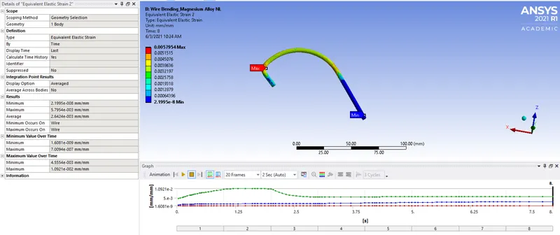
III. EQUIVALENT STRAIN FOR WIRE:
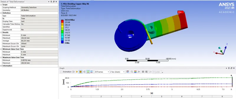
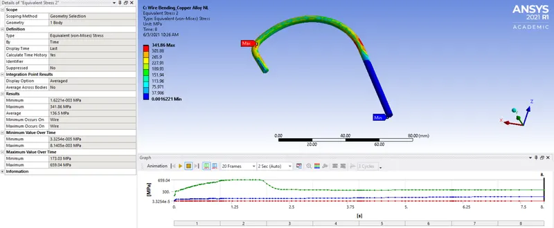
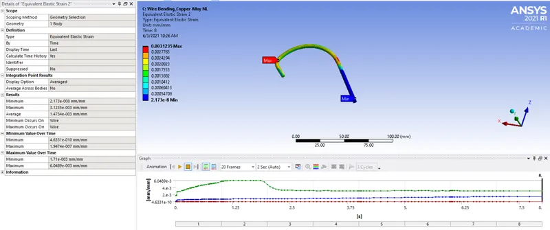
Case 3: Copper Alloy NL
I. TOTAL DEFORMATION:
II. EQUIVALENT STRESS FOR WIRE:
III. EQUIVALENT STRAIN FOR WIRE:
VII POST-PROCESSING SUMMARY:
|
Parameters |
Aluminum Alloy NL |
Magnesium Alloy NL |
Copper Alloy NL |
|
Maximum Deformation |
262.64 mm |
262.64 mm |
262.64 mm |
|
Minimum Deformation |
0 |
0 |
0 |
|
Maximum Equivalent elastic strain for wire |
4.2632e-003 mm/mm |
5.7954e-003 mm/mm |
3.1235e-003 mm/mm |
|
Minimum Equivalent elastic strain for wire |
7.2727e-008 mm/mm |
2.1995e-008 mm/mm |
2.173e-008 mm/mm |
|
Maximum Equivalent stress for wire |
299.39 MPa |
259.71 MPa |
341.86 MPa |
|
Minimum Equivalent stress for wire |
3.1388e-003 MPa |
7.1321e-004 MPa |
1.6221e-003 MPa |
CONCLUSION:
Based on the obtained results, we can find the aluminium alloy NL has the highest capacity to withstand the load while bending than the other two materials with the highest equivalent elastic strain than the other two.
Thus structural analysis to simulate the bending of wire considering three different case setup cases has been performed and the results were compared.