Week 4 -Wire Bending Challenge
Aim:
The aim of this project is to analyse a wire under bending with three different non-linear materials copper, aluminium and magnesium alloys.
Model Set-up:
Geometry: CAD model was imported into the static structural workbench. In the material library required materials are added such as Copper, Aluminium, and Magnesium alloy as shown in image 1.
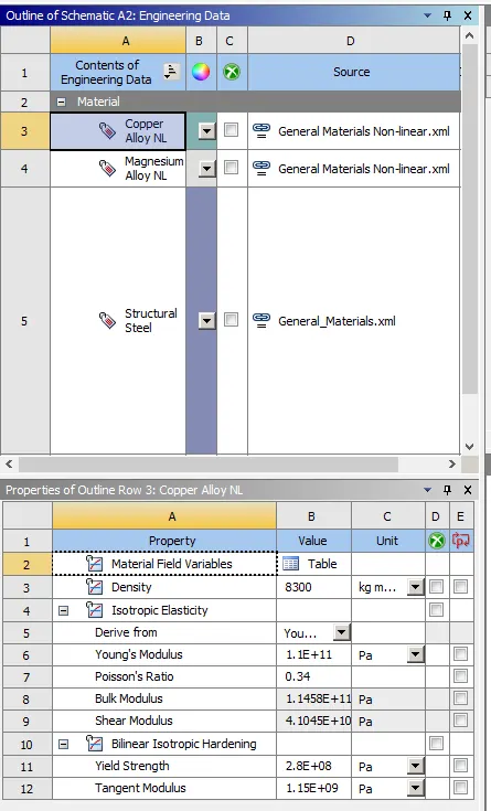
Image 1: Material library
Connections:
The frictional contacts are defined between wire to lever and wheel to wire with a frictional coefficient of 0.2, augmented Lagrange formulation with normal stiffness factor of 0.1 for each iteration. The contacts are shown in image 2.
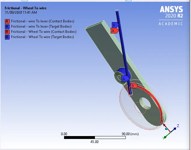
Image 2: Contacts definition
A revolute joint is defined at the inner centre of lever rotating in the z-direction.
Mesh: A method is applied to all the parts with tetrahedrons. A face sizing of the 2.2mm was applied to the critical area of simulation as shown in image 3. A body sizing of with element size 0.8mm was given to a sphere of influence as shown in image 4. The image of the meshed parts is given is image 5.
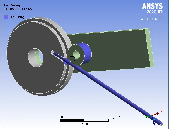
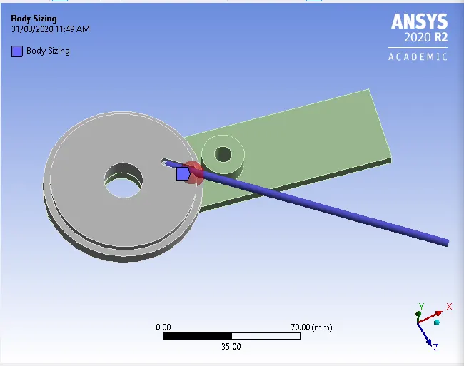
Image 3: Face mesh surfaces Image 4: Body sizing at the sphere of influence

Image 5: Meshed parts
Analysis Settings:
The analysis is set for 8steps defined by time with carryover time from minimum time step 0.002 and a maximum time step of 1s and direct solver type.
The inner surface of the wheel is fixed. The corner of wire inside the wheel is fixed. A rotation is defined as the joint as shown in image 6.
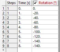
Image 6: Joint loading.
Results and Conclusions:
The results for stress and strain of the wire alone are tabulated in table 1:
| Non- Linear Material | Equivalent Stress (MPa) | Equivalent strain (mm/mm) |
| Copper Alloy |
Max 322.99 Min 0.0046278 |
0.0029408 6.3424e-8 |
| Aluminium Alloy |
Max 312.2 Min 0.0039335 |
0.004424 8.372e-8 |
| Magnesium Alloy |
Max 258.6 Min 0.0018892 |
0.0057639 6.5526e-8 |
The stress and strain results for copper wire bending are given in image 6 and 7 respectively:
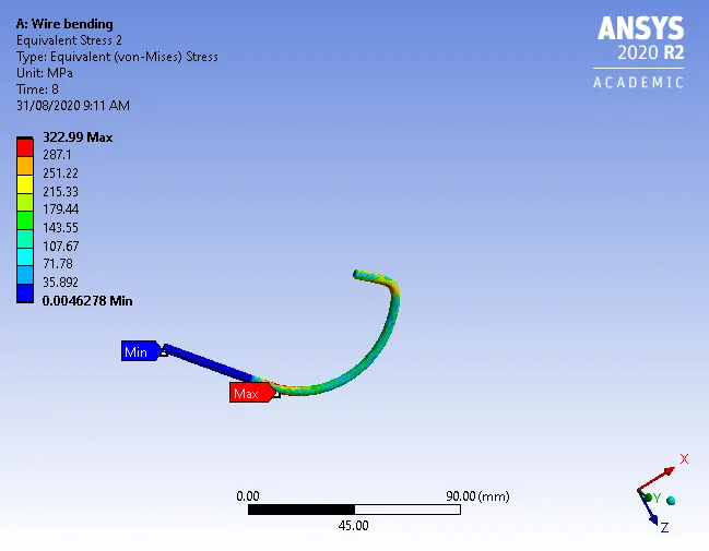
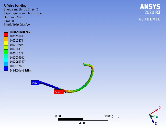
Image 6: Stress developed on a copper wire Image 7: Strain developed on a copper wire
The stress and strain results for aluminium wire bending are given in image 8 and 9 respectively:
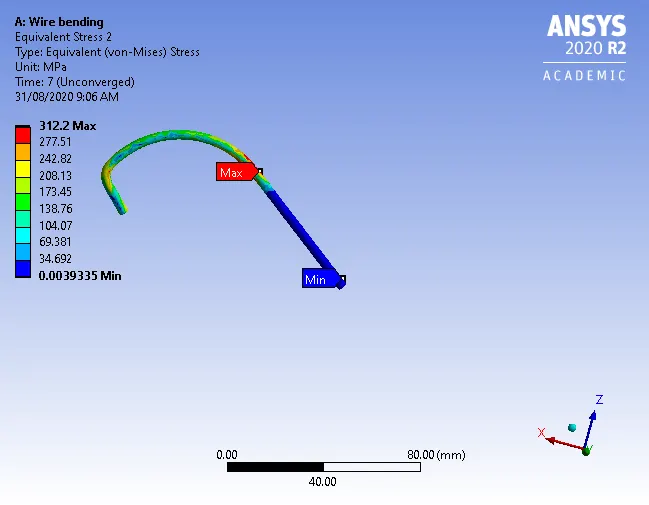
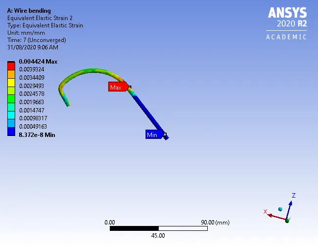
Image 8: Stress developed on an aluminium wire Image 9: Strain developed on an aluminium wire
The stress and strain results for magnesium wire bending are given in image 10 and 11 respectively:
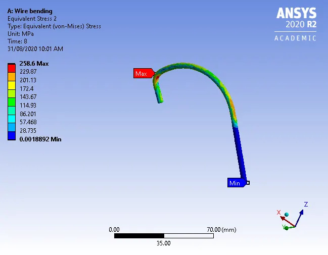
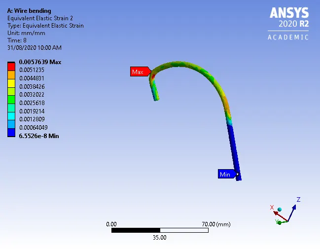
Image 10: Stress developed on a magnesium wire Image 11: Strain developed on a magnesium wire
Conclusions:
- Maximum stresses are observed at the maximum deformation points such as at the contact of roller and wire, bending at the level position.
- From the above results, we can conclude that when the young modulus is higher for the material stresses developed are high.
- Since copper has highest youngs modulus it has more stress developed and less strain developed. Since magnesium has lower youngs modulus strain is higher and stress is lower.
- According to the application material for rolling can be chosen but when it comes to the rigidity of the material aluminium is better compared to other two materials as both the stress and strain are in acceptable limits and well under its ultimate failure values.