Week 4 Session 5
In the electric vehicle (EV) powertrain, all the electric input sources are connected to a HV–DC bus by an individual DC–DC converter, and the output three-phase electric motor (EM), i.e., the main load of the EV, is powered from this HV–DC bus through a three-phase inverter which drives the EM. Here, the voltage level of this HV–DC bus of the EV is around 400–750 V. Moreover, moving the EV via an EM from electric batteries, a DC–DC voltage is required because the batteries’ output voltage is much lower than the required voltage of EM. A traction inverter is needed to drive the EM by converting the DC batteries into variable-frequency AC. However, a disagreement could be made for stepping up the output AC voltage level of the inverter by utilizing a high-voltage transformer instead of a DC–DC converter. This is due to its having several essential advantages, such as reliability, cost-effectiveness, compact size, and lightweight DC–DC converters appear to be excellent candidates for EVs and HEVs powertrains.

The various power converters used in EVs are :
1. AC-DC power converters (Rectifiers):
-In case of a Hybrid EV the AC power generated during by the generator needs to be converted into DC to be able to store it into the on-board Battery.
-In BEVs and HEVs both, the battery of the vehicle works on DC power. The utility provides AC supply and thus to charge the battery of the vehicle, a rectifier circuit has to be used to convert this grid supply into the DC supply required by the battery.
-Battery Charger: EV battery chargers can be classified as on-board and off-board with unidirectional or bidirectional power flow. Unidirectional charging limits hardware requirements simplifies interconnection issues and tends to reduce battery degradation. A bidirectional charging system supports charge from the grid, battery energy injection back to the grid, and power stabilization with adequate power conversion.
2. DC-AC converter (Inverter):
The most commonly used motors used in electric vehicles are 3 phase Induction Motors. These motors require AC supply to run at the desirable speeds. However, the ESS used in the vehicle stores DC power.
-Inverter is a power converter that converts this DC power into AC power required by the induction motors. The DC/AC inverter also performs the function of recharging the batteries during regenerative braking in HEVs.
- Also, Inverters are used for supplying utility loads such as Air conditioning and power outlets. Inverters are generally classified into voltage-fed and current-fed types. Because of the need of a large series inductance to emulate a current source, current-fed inverters are seldom used for EV propulsion.
In fact, voltage-fed inverters are almost exclusively used because they are very simple and can have power flow in either direction.
The semiconductor switches in each arm switch in regular intervals in order to generate a AC voltage waveform.
2.1. Two-Level Inverter (TLI)
The two-level inverter which consists of six power-switching devices. These six power switches are connected into three legs, and each leg contains two switches, which are connected in series. An antiparallel diode is connected to each switch to allow the current to flow in the opposite direction. By controlling these six switches in different manners, the inverter can generate eight other states.
2.2. Multi-Level Inverter (MLI)
To gain less current and voltage total harmonic distortion (THD), less voltage stress on semiconductor devices, high efficiency, low EMI, and common-mode voltage, many conventional two-level inverters have been replaced in the past decades by their multilevel counterparts. In addition, due to the modularity and fault tolerance capability, some MLI topologies becomes more beneficial for specific applications. The basic concept of an MLI is where switching devices carry much lower voltages than TLI, and the output filter size is decreased due to the ability to produce various voltage levels with better voltage/current quality at the lower switching frequency. As a result, higher power levels can be achieved with MLIs without switches derating.
3. DC-DC Converter :
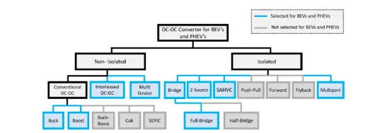
A DC/DC converter in its basic form converts unregulated DC input voltage at a certain level to a regulated DC output voltage at a different level with very high conversion efficiency (>90%).
-Modern day DC/DC converters are operated at high frequencies (10 kHz - 1 MHz). The size of the components such as inductors, transformers, and capacitors are reduced at high frequency operation. Transistors such as MOSFETs and IGBTs are used as switches.
-The former is preferred in high frequency, low and medium power applications, whereas the latter is preferred in low frequency high power applications. The switches are turned ON and OFF by pulse width modulation (PWM) technique.
DC-DC converters are used to supply auxiliaries of the vehicle and functions like:
-Providing low voltage (12V or 14V) for low voltage loads. (Step-down Chopper)
-Boosting the voltage level of the battery such that it matches the level of the DC bus voltage for driving the AC motor inverter if the traction motor is AC motor (Step up chopper)
-Motor propulsion if the traction motor is a DC motor.
The most common DC/DC converters used in EV are:
-Non-isolated converters
The non-isolated converters type is generally used where the voltage needs to be stepped up or down by a relatively small ratio . And when there is no problem with the output and input having no dielectric isolation.
There are five main types of converter in this non-isolated group, usually called the buck, boost, buck-boost, Cuk and charge-pump converters.
Buck- A buck converter (step-down converter) is a DC to DC power converter which steps down voltage from its input (supply) to its output (load). It is a class of switched mode power supply (SMPS) typically containing at least two semiconductors a diode and a transistor, although modern buck converters frequently replace the diode with a second transistor used for synchronous rectification and at least one energy storage element, a capacitor,inductor, or the two in combination. To reduce voltage ripple, filters made of capacitors (sometimes in combination with inductors) are normally added to such a converter's output (load-side filter) and input (supply-side filter).
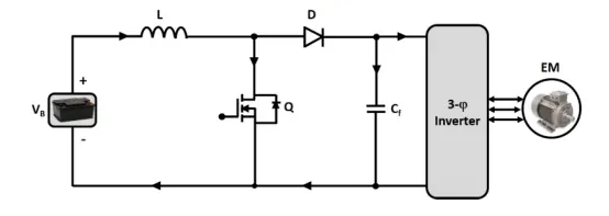
Boost- A boost converter (step-up converter) is a DC to DC converter that steps up voltage from its input (supply) to its output (load). It is a class of switched mode power supply (SMPS) containing at least two semiconductors a diode and a transistor and at least one energy storage element: a capacitor,inductor or the two in combination. To reduce voltage ripple, filters made of capacitors (sometimes in combination with inductors) are normally added to such a converter's output (load-side filter) and input (supply-side filter).
Buck-boost- The buck–boost converter is a type of DC to DC converter that has an output voltage magnitude that is either greater than or less than the input voltage magnitude. It is equivalent to a flyback converter using a single inductor instead of a transformer.
Cuk- The Ćuk converter is a type of buck-boost converter with zero ripple current. Ćuk converter can be seen as a combination of boost converter and buck-converter, having one switching device and a mutual capacitor, to couple the energy.
charge-pump- A charge pump is a kind of DC to DC converter that uses capacitors for energetic charge storage to raise or lower voltage. Charge-pump circuits are capable of high efficiences, sometimes as high as 90–95%, while being electrically simple circuits.
-Isolated converters
Usually, in this type of converters a high frequency transformer is used. In the applications where the output needs to be completely isolated from the input, an isolated converter is necessary. There are many types of converters in this group such as Half-Bridge, Full-Bridge, Fly-back, Forward and Push-Pull DC/DC converters. All of these converters can be used as bi-directional converters and the ratio of stepping down or stepping up the voltage is high.
Half bridge: A half-bridge converter is a type of DC-DC converter that, like flyback and forward converters, can supply an output voltage either higher or lower than the input voltage and provide electrical isolation via a transformer.
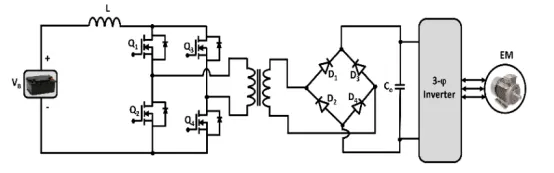
Full bridge: The full-bridge converter adds two additional transistors to the half-bridge converter. This means that four transistors are available to provide power to the output section, so this type of converter is used in power supplies in excess of 1000 Watts. Each transistor has a clamping diode connected across its collector-emitter terminals and they are driven alternately in pairs. Transistors T1 and T3 are energized together for one half-cycle, and transistors T2 and T4 are energized together for the other half-cycle. One advantage of the full-bridge converter is that it only requires one capacitor for smoothing the output voltage, whereas the half-bridge converter required two. The full-bridge converter will be used in larger power supplies usually over 1000 Watts. Since this type of converter is more complex, it's normally used in the largest types of power supplies.