Week 4- Rolling operation
Copper running simulation in ANSYS Workbench:
AIM:
To study and perform structural analysis of a rolling operation of copper piece. Grid dependency test was also performed to optimize the element size for better accuracy. Basically, as per requirement we have to find below parameters:
- Equivalent stress for the whole setup
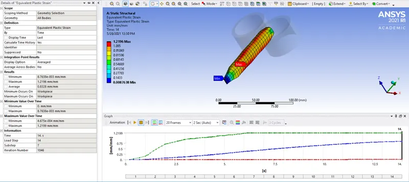
- Equivalent Plastic strain for the workpiece
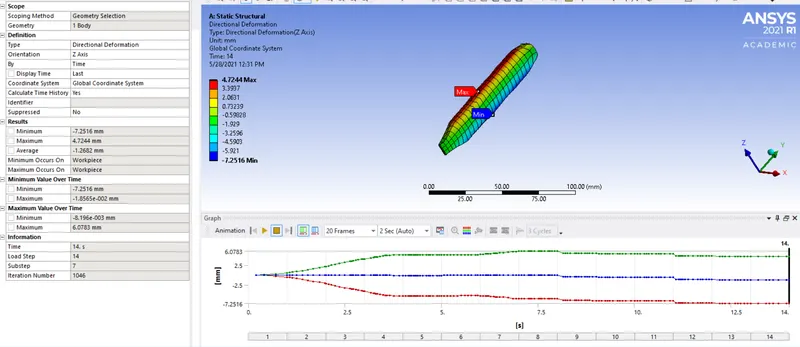
- Directional Deformation in the Z axis for the workpiece
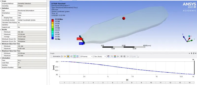
- Prove that the workpiece has displaced by 90mm.
ANALYSIS SETUP FOR ROLLING OPERATION:
I. GEOMETRY:
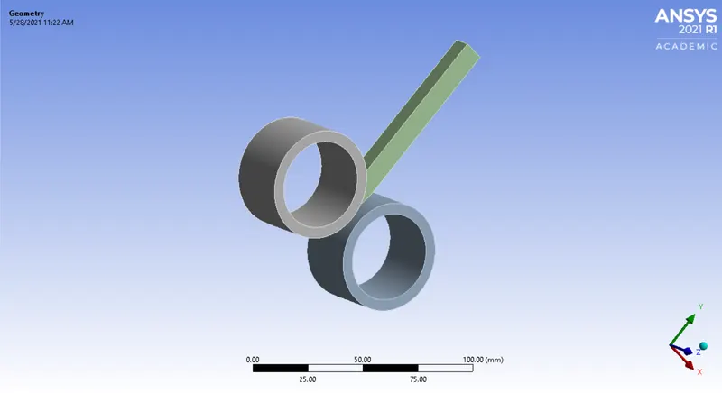
The CAD model of rolling operation is imported in Ansys static structural environment. Certain changes we have made in spaceclaim, the height is increased to 60 mm and width is reduced by 8 mm on both sides. It comprises of three components namely Wheel 1, Wheel 2 and workpeice.
II. MATERIAL:
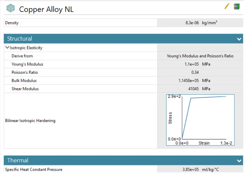
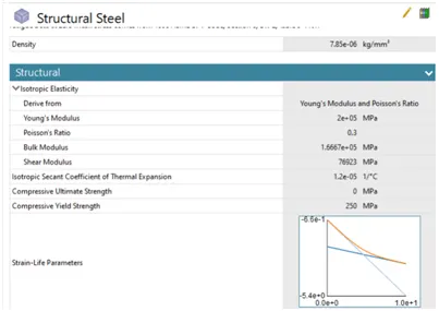
Below are the materials which is used to perform analysis for the rolling operation. The analysis is carried out for each material individually. For wheel 1 and wheel 2 we have specified Structural steel and for workpeice we have specified Copper alloy NL as material.
The details of each material is carried out and shown below:
III. CONNECTION DETAILS:
(A) CONTACT DETAILS-
1. Frictional- Workpeice to Wheel 1:
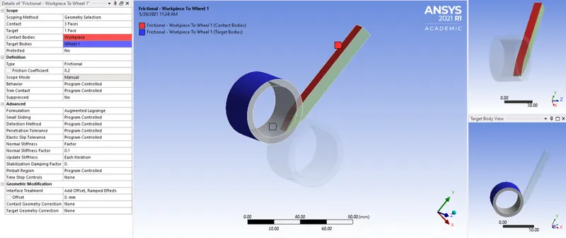
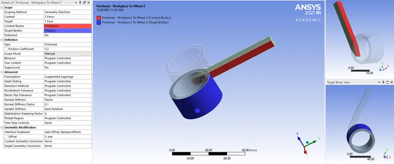
Frictional contact is given below between faces of workpeice and wheel 1. as shown in the image below. The 3 faces of workpeice came in contact with 1 face of wheel 1. with a frictional coefficient of 0.2. Then the behaviour of geometry is changed to Program controlled and then the formulation is changed to Augmented Lagrange. Also, normal stiffness factor of 0.1 is assigned to the contact faces. Then, make the update stiffness as 'Each iteration'. Lastly, interface treatment in geometric modification is assigned as 'Add offset, Ramped effects.'
2. Frictional- Workpeice to Wheel 2:
Frictional contact is given below between faces of workpeice and wheel 2. as shown in the image below. The 3 faces of workpeice came in contact with 1 face of wheel 2. with a frictional coefficient of 0.2. Then the behaviour of geometry is changed to Program controlled and then the formulation is changed to Augmented Lagrange. Also, normal stiffness factor of 0.1 is assigned to the contact faces. Then, make the update stiffness as 'Each iteration'. Lastly, interface treatment in geometric modification is assigned as 'Add offset, Ramped effects.'
(B) JOINT DETAILS-
1. Cylindrical- Ground to Wheel 1:
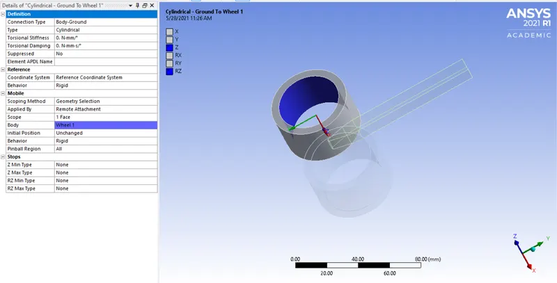
In this joint, we have to select wheel 1. as geometry selection part. Then we have to change the connection type and connection as 'Body-Ground' and 'Cylindrical'. After that we have to select the reference coordinate system in Z-axis.
2. Cylindrical- Ground to Wheel 2:
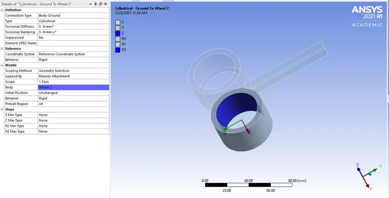
In this joint, we have to select wheel 2. as geometry selection part. Then we have to change the connection type and connection as 'Body-Ground' and 'Cylindrical'. After that we have to select the reference coordinate system in Z-axis.
IV. MESH:
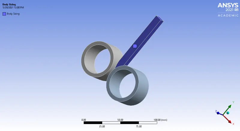
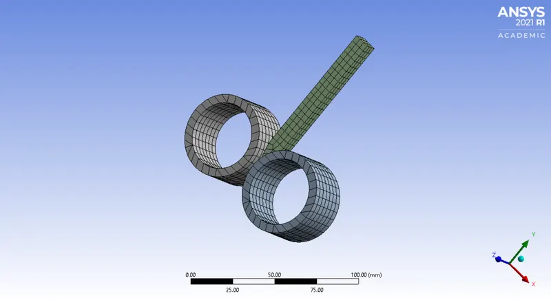
- Basically, we have meshed the roller with a deafult mesh of 5 mm.
- Then, sizing is provided for the workpeice and it is meshed with 4 mm element size.
- At this type, the fine mesh is generated which is sufficient to carry out simulation which gives desired results.
V. BOUNDARY CONDITIONS AND ANALYSIS SETTINGS:
(A) ANALYSIS SETTINGS:
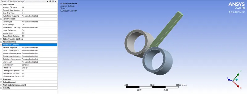
For this analysis the number of steps is set to 14 with Auto Time stepping is program controlled. After that, Large deflection is set to On, so as to account for change in stiffness due to change in shape of gears. When stabilizations are activated, it adds dampers to all nodes. When the large displacement nodes try to move the force is added to balance them thus favoring convergence. Hence, the energy dissipiation is said to be 0.1.
(B) BOUNDARY CONDITIONS:
1. Displacement Load:
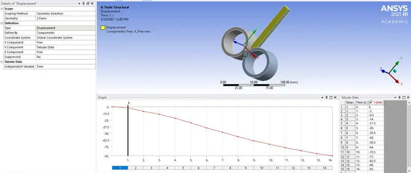
Basically, we have to select the faces on workpeice as geometry. Then, its type is considered as displacement and then its Y axis get's value from tabular form. After that, we have to select the both sides of workpeice and then given a displacement of 90 mm in negative Y-axis direction. Then, its value is ploted around graph.
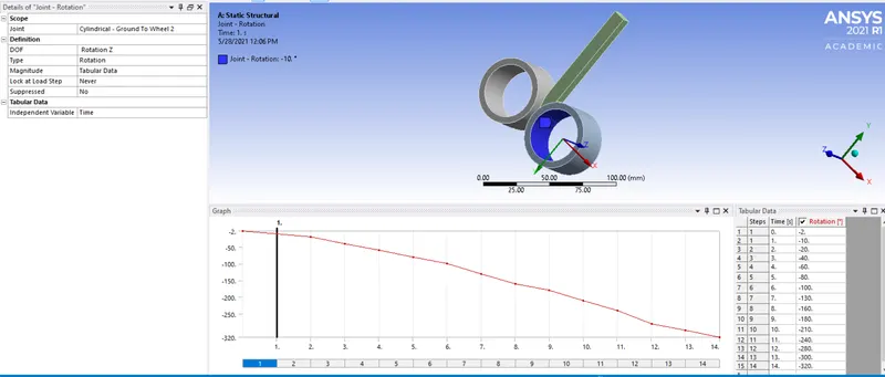
2. Joint-Rotation 1:
As, we have to select the joint as 'Cylindrical- Ground to Wheel 1'. Then, we have to select the type as 'Rotation'. Lastly, we have set magnitude in anti-clockwise direction as tabular data.
3. Joint-Rotation 2:
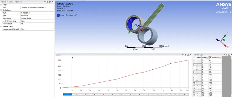
As, we have to select the joint as 'Cylindrical- Ground to Wheel 2'. Then, we have to select the type as 'Rotation'. Lastly, we have set magnitude in clockwise direction as tabular data.
VI. POST-PROCESSING RESULTS:
Now, we have to compare the deformation and stress on the basis of different materials. Then, we have to analyze the result for Directional deformation, equivalent elastic strain and equivalent stress for weld joint. The results are as shown below:
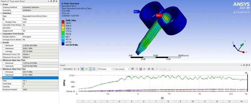
1. EQUIVALENT STRESS:
The wheels were modeled as rigid bodies, but still it is possible to obtain a resonable estimate of its normal stress (negligible shear stress) from the normal pressure acting on it at the contact.
The materials and the geometry of the roller should be able to function at such high contact pressures.
The stress increases as the work peice enter the region between the roller and then decreases to a contact value as the workpeice moves out of the rollers.
2. EQUIVALENT PLASTIC STRAIN FOR WORKPIECE:
3. DIRECTIONAL DEFORMATION(Z-AXIS) FOR WORKPIECE:
4. WORKPEICE HAS DISPLAYED BY 90 MM:
VII. POST PROCESSING SUMMARY:
|
Parameters |
Rolling operation |
|
Maximum Directional Deformation |
4.7244 mm |
|
Minimum Directional Deformation |
-7.2516 mm |
|
Maximum Equivalent Plastic strain |
1.2196 mm/mm |
|
Minimum Equivalent Plastic strain |
8.7638e-003 mm/mm |
|
Maximum Equivalent stress for weld |
2048.1 MPa |
|
Minimum Equivalent stress for weld |
2.3078e-002 MPa |
CONCLUSION:
Hence, the overall structural analysis to simulate the rolling operation on a copper workpeice of length 90 mm is performed and proved.