Week 4- Rolling operation
Objective: To run the rolling operation using workpiece material as Copper alloy and evaluate.
Change the dimension of workpiece as mentioned in the guidance and evaluate all the results accordingly.
Case Setup:
- Open Ansys Workbench & load static structural.
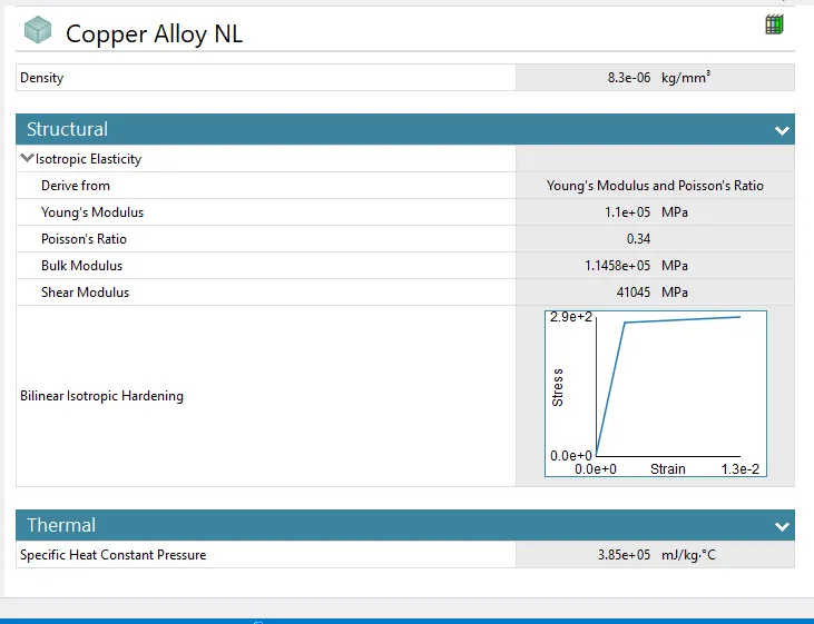
- Open engineering material and select Copper alloy NL as we might use the same for workpiece.
- Load the geometry from the required file and open it in space claim.
- Reduce the width and increase the length of workpiece by choosing pull option. Check if the geometry is correct and load the same.
- Update the model and select edit to open the same. Once it has opened we can rename the parts such as Wheel1, Wheel2 & Workpiece. Choose Copper alloy for Workpiece and other rollers as structural steel.
- Now moving to contact flip the contact and choose rename based on definition. In the first contact select roller as target and single face of workpiece as contact. Provide frictional value of 0.2, normal stiffness factor of 0.1 & Interface treatment as Adjust to touch .Similarly repeat the same procedure for the 2nd
- Next in connections add two revolute joints for the circular rollers and select inner face of the roller for scope and let both the roller rotate about z direction.
- Now in mesh select 4 mm of mesh for workpiece & 2 rollers. We can also refine the mesh size for more accurate results but that will take more time to complete the simulation.
- Further moving on to analysis setting select no of steps as 14.Let the auto time stepping be on, define by time with minimum time step as 0.1 & maximum time step as 1.Set Large deflection to be on, stabilization to constant and energy dissipation ratio as 0.1.
- Now insert displacement for the workpiece as it will travel between two rollers. Provide a displacement with no of steps from 0 to 90mm with small increment in displacement.
- Insert two joint load for two rollers and provide a rotation to both the rollers with small increment of 15 degree in 14 steps.
- Now load the various stress deformation and strain as required and Hit Solve.
Results :
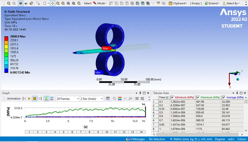
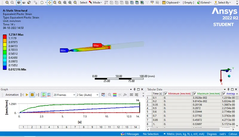
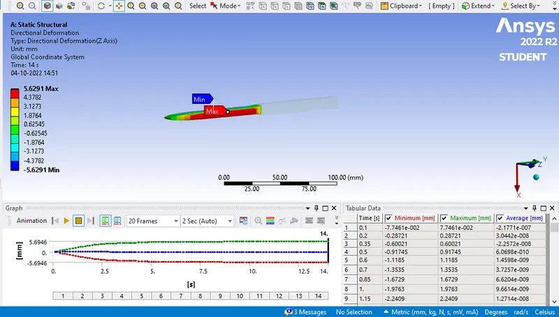
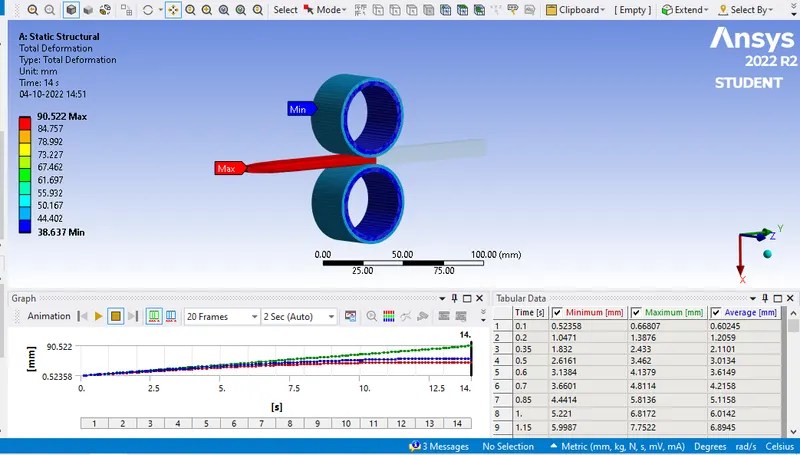
Maximum equivalent stress is 2868.9Mpa , plastic strain is 1.2561mm.Also in direction of rotation 'z' we get a directional deformation of 5.6291mm. Total deforamtion can be seen as 90.522mm.Mesh size of 4mm is used all over the surface. Material is Copper alloy Non-Linear.
|
Sr No |
Material |
Mesh Size |
Equivalent Stress Max (Mpa) |
Equivalent Plastic Strain Workpiece (Max) |
Total Deformation (Max in mm) |
Directional Deformation (mm) |
|
1. |
Copper Alloy Non-Linear |
4mm |
2868.9 |
1.2561 |
90.522 |
5.6291 |
Conclusion:
In the above simulation we can observe that by choosing workpiece material as Copper alloy we get a maximum stress as 2868.9Mpa & Plastic strain in workpiece is 1.2561mm.Total deformation defines the maximum deformation that is observed in the workpiece. From the above results it can be seen that the deformation is 90.522 mm so it means that workpiece is displaced by 90mm. Also we can observe that a directional deformation of 5.6291mm has been seen in z axis. Similarly various pressure and other values can be evaluated as required. Also to obtain most precise results we can reduce the mesh size of workpiece.
Note - All the files showed as image,animation & simulation files are attached in required format for your reference.