Week 4- Rolling operation
Objective: The aim of this project is to conduct a rolling operation on a copper model.
Model Set-up:
A static structural workbench was setup.
Geometry:
The CAD geometry is imported into SpaceClaim and the workpiece was increased in length by 60mm and its size on both sides was decreased with 8mm.
Material:
The general non-linear material of copper is added to the material library. The property is assigned to the workpiece in Ansys mechanical.
Connections:
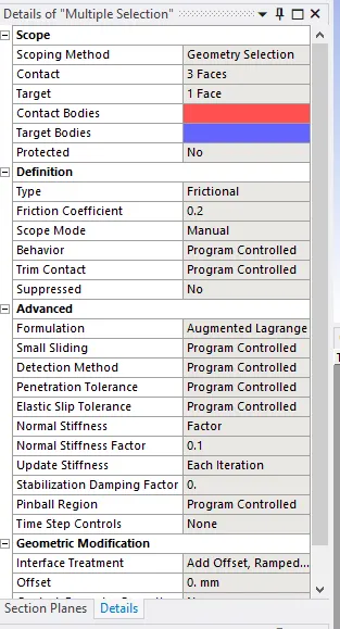
Contacts: Contacts were defined between Top wheel and the top part of the copper workpiece; bottom wheel and the bottom part of the copper workpiece. Frictional contact definition was given with 0.2 frictional coefficients. Augmented Lagrange formulation was defined. A normal stiffness factor of 0.1 and updating it for each iteration was defined. The interface treatment was defined to add the offset and ramped effect as shown in the below images.
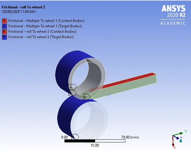
Joints: The joints were defined to be the body-ground connection and cylindrical type for both the wheels inside surfaces.
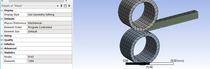
Mesh: The mesh size of 2mm was given to the copper workpiece as it is our focus. The number of nodes was 9143 and 1594 elements as shown in below image.
Analysis settings:
The analysis was set for 14 steps with constant energy stabilization and dissipation ratio of 0.1 in non-linear contacts. Large deformation is set ON.
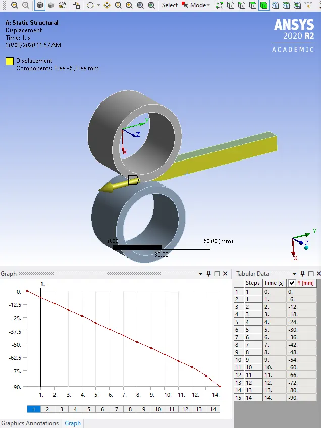
Displacement was defined in negative y-axis for all the steps as shown in the below image:
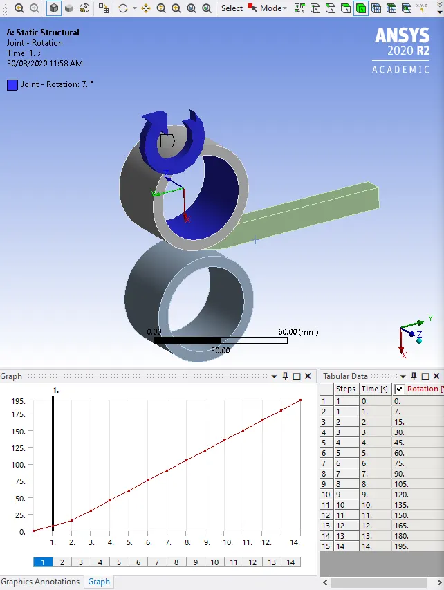
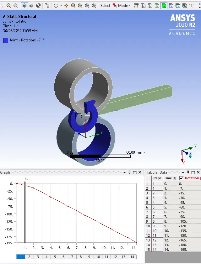
Both the joints were given cylindrical rotation in z-axis with a degree magnitude as shown in images:
Solution setup:
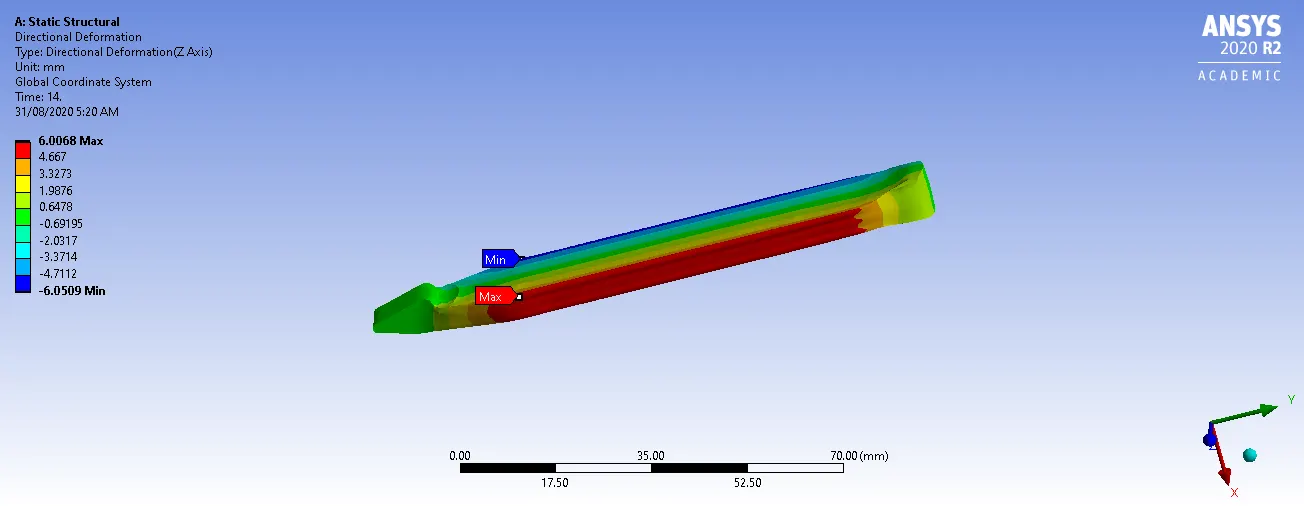
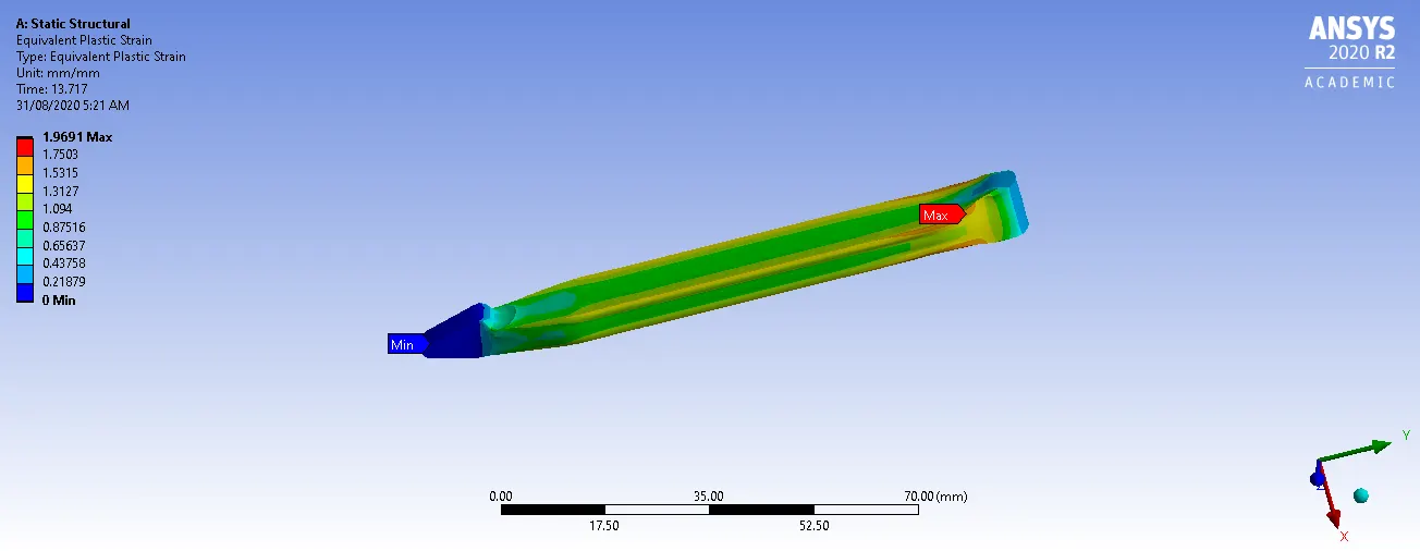
The results for directional deformation of the copper workpiece, the equivalent plastic strain of the copper workpiece, equivalent stress for the whole model, and directional deformation for the tip of workpiece were asked.
Results and Conclusions:
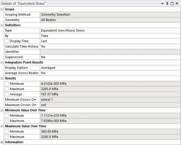
The results are tabulated in the below table:
| Equivalent Stress for the whole setup | Directional deformation of the workpiece in the z-direction | Equivalent Plastic strain of the workpiece | |
|
Maximum Minimum |
3265.9 MPa -0.0040102 MPa |
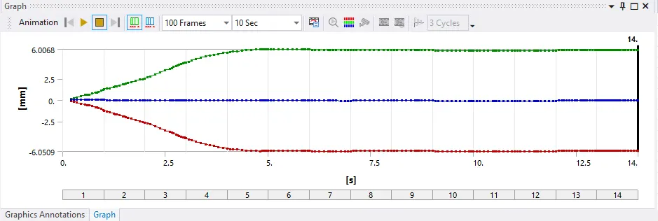
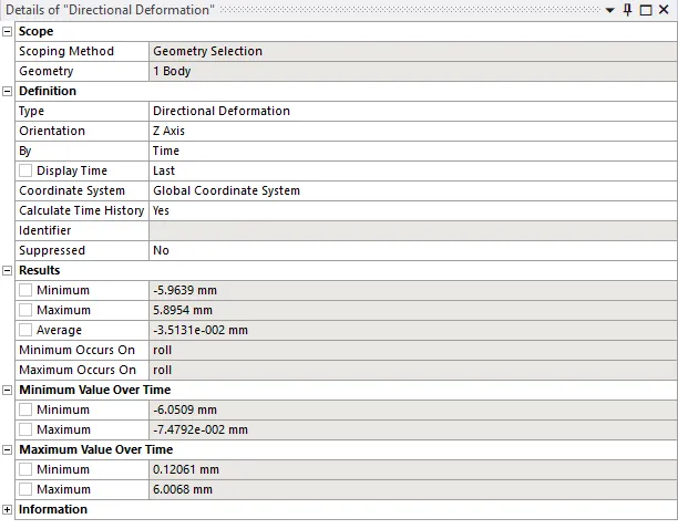
5.8954mm -5.9639 |
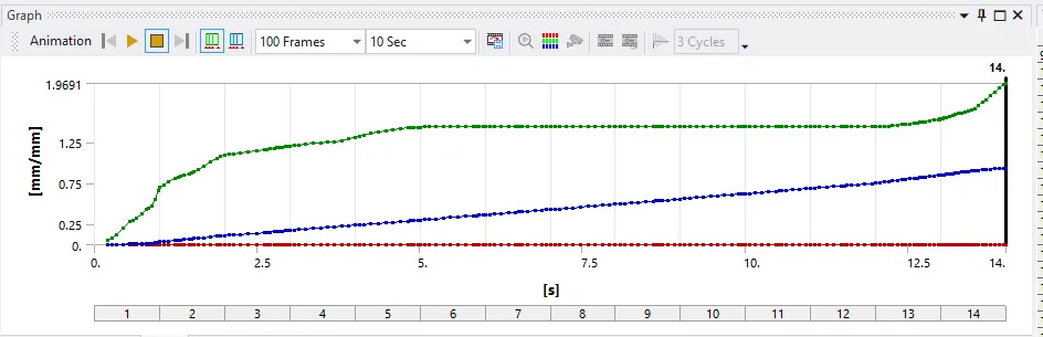
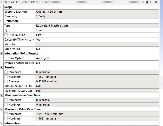
1.9691 0 |
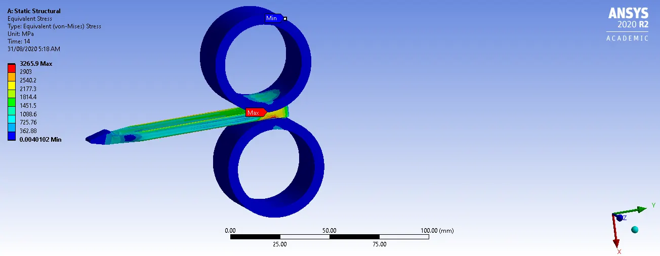
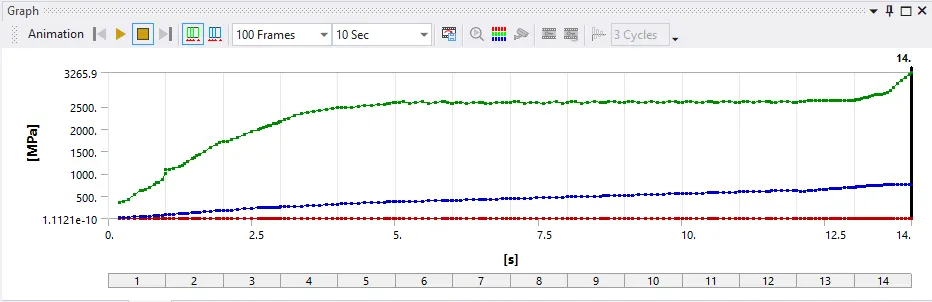
The images for stress are given below:
The images for directional deformation of the workpiece in the z-direction are given below:
The images for equivalent plastic strain are given below:
The proof that the workpiece has displaced by 90mm:
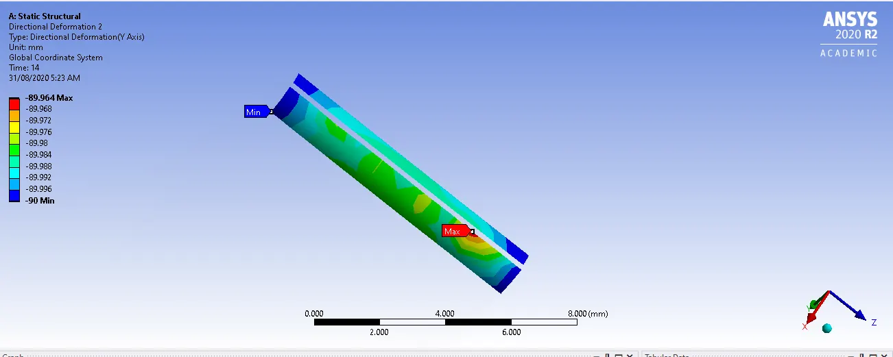
From the above results, we can conclude that the maximum stress is observed at the end of the contact between rollers and workpiece as the stresses from before are accumulated at the end. There are no stresses on the rollers as they do not undergo any deformation. The maximum deformation occurs at the left end of the workpiece. Similar to equivalent stress the strain is carried over from before steps to the end of the workpiece. Results prove that the model has displaced 90mm in the y-direction.