Week 4: Project - Transient simulation of flow over a throttle body
AIM: To perform Transient State simulation over a throttle body.
Litrature Review:
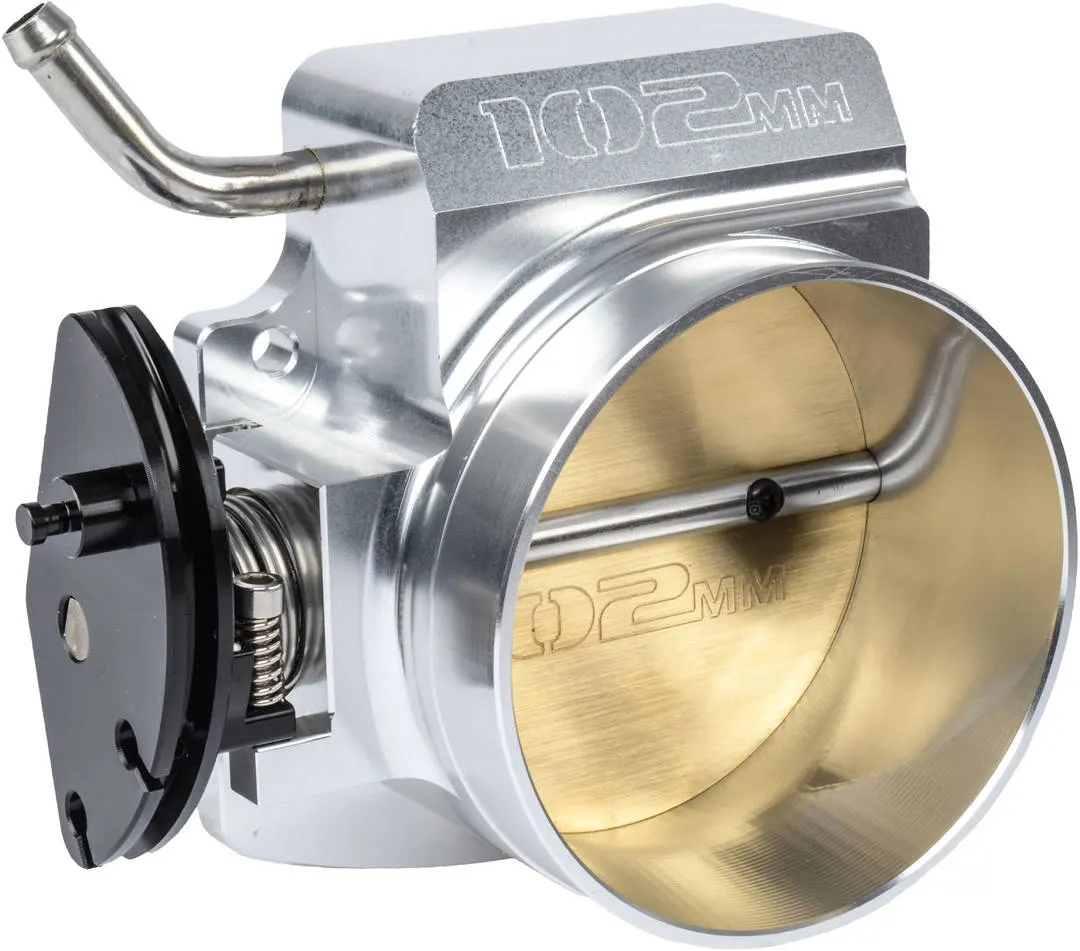
A throttle body is an arrangement in the engine which controls the air flow into the engine based on the inputs given by the driver. Usually, the butterfly valve is connected to the pedal with a throttle wire which is inturn connected to a mechanism which alters the position of the valve based on input. However as technology advanced, this system has become electric. Below is an image of a throttle body.
SETUP
The profile of the throttle body was created in a CAD software and converted into the STl format. This converted file is loaded into the converge studio application and the further setting of parameter is done using the same.
Procedure to setup the case:
- Select time based in the application.
- We select Air as the premixture in the material section of the setup tree. We must also ensure that the simulation type is gas.
- In the simulation parameters, we select the transient solver and make sure that the type of simulation is full hydrodynamic. (Usually, simulations are run in non-hydrodynamic mode to ensure that the grid formed on the case is as expected. Due to the simplicity in the geometry, we directly use the full hydrodynamic mode.)
- We setup the boundaries as required also we assign the region to each of the boundary.
- We perform the calculation for flow through time to run the simulation. In a transient simulation, the time parameters are set in seconds in contrast to cycles in the steady state simulation. The formula for calculating the same will be mentioned below further in this report.
- Here we employ the turbulence modeling where we use the RANS method and we use the RNG k `epsilon`
- We also use fixed embedding for a refiend mesh at the throttle (Butterfly valve).
Few particulars
Pressure at inlet: 150000 Pa
pressure at outlet: 100000 Pa
Temperature Boundary condition: 300K
Species Boundary conditions:
O2= 23%
N2=77%
Simulation parameters
Total number cycles= 15000 cyc
minimum time steps=1e-9s
maximum time step=1s
Boundary conditions:
Inlet : INFLOW Pressure: 150000pa Species : AIR
Outlet : OUTFLOW Pressure:100000pa Species: AIR
Elbow:
Wall Type: Stationary
surface motion: FIXED
Law of wall condition
Boundary temperature:300K
Throttle:
Wall Type: Rotating
surface motion: Moving
Law of wall condition
Boundary temperature:300K
Calculation of Flow through Time:
`"Flow through time" = "Characterstic length" / "Velocity"`
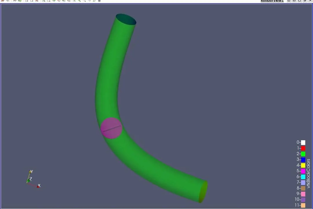
View of the Throttle Body:
Mesh:
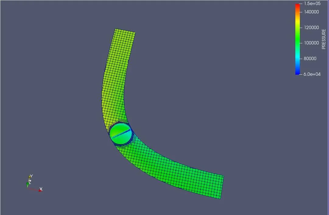
A mesh size of 2mm was chosen for this simulation.
Note: The method employed by converge for the application of mesh is known as the cut cell cartesian method.
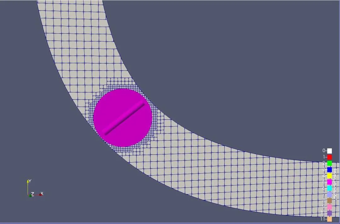
The denser mesh near the throttle valve is present due to the fixed embedding function used in the setup.
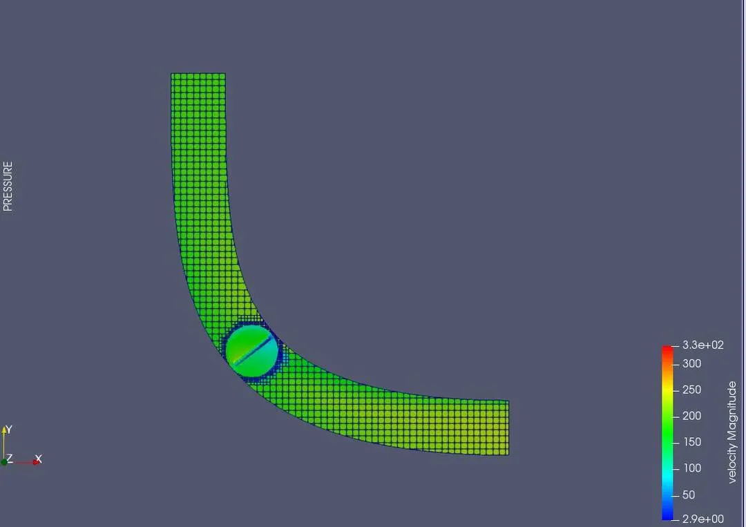
VELOCITY PROFILE:
Pressure Profile:
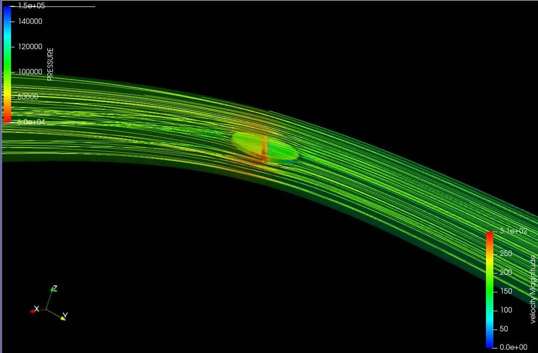
Flow Lines:
When valve is at an inclination of 25 degrees:
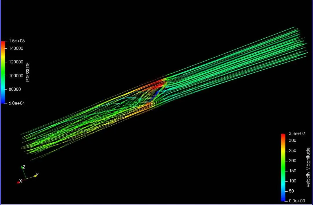
The angle is to be maintained at 25 degrees from 2 to 4 milliseconds.
When valve is at an inclination of 0 degrees (Start and End):
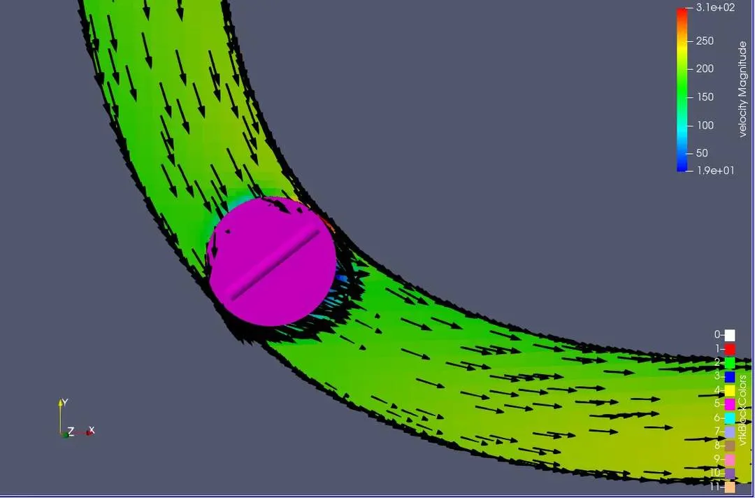
Flow Vectors:
When valve is at an inclination of 25 degrees:
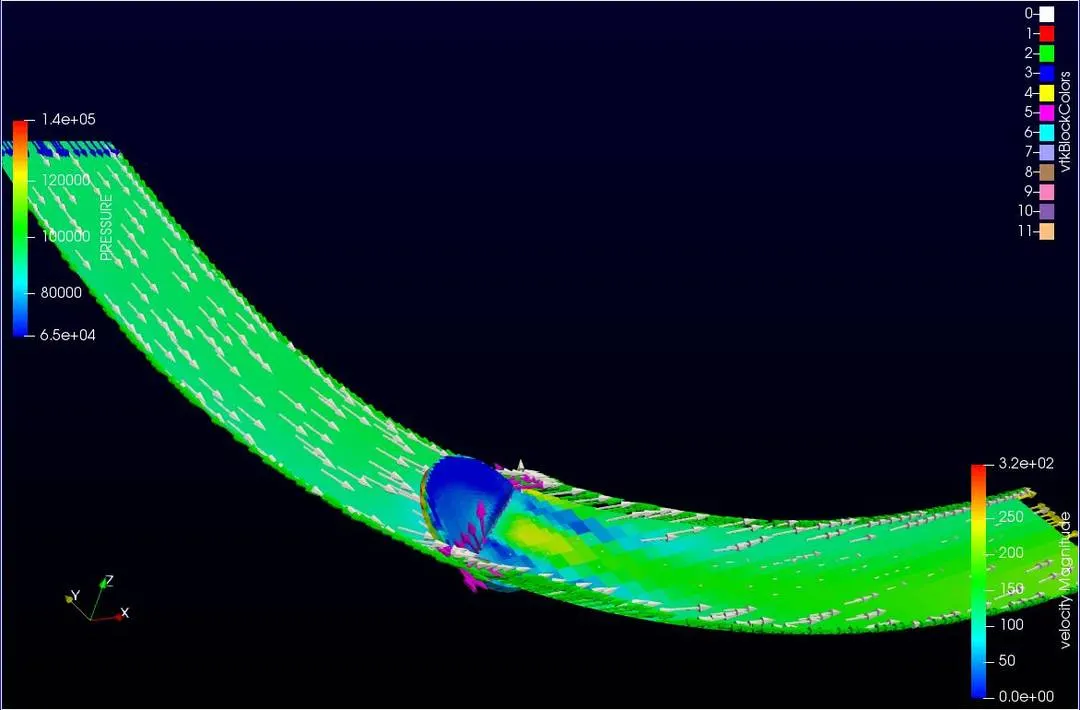
When valve is at an inclination of 0 degrees:
Plotting the Results on Converge Studio:
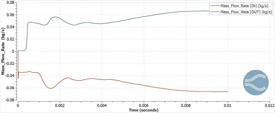
Mass flow rate:
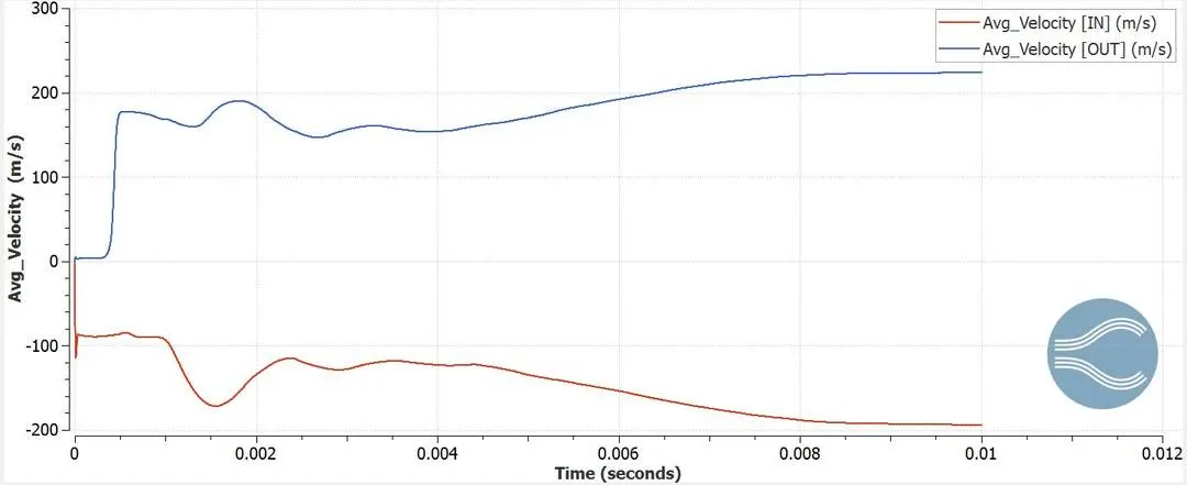
Velocity:
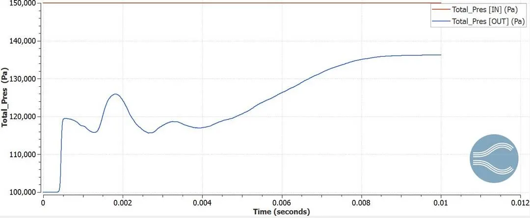
Pressure:
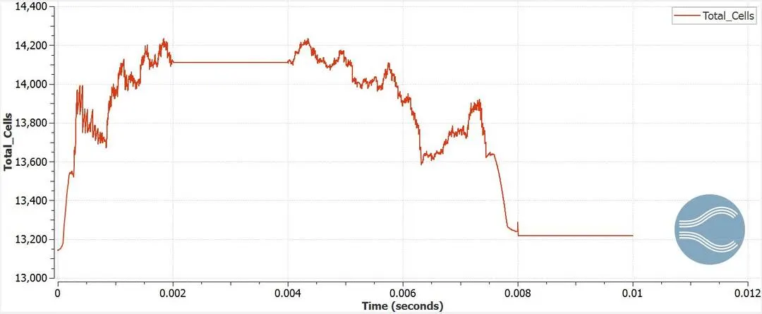
Total Cell Count:
Inferences from the plots:
Mass Flow Rate Plot: From the plot we can observe some unstability and decrease in the mass flow rate as the butterfly valve is at an angle of 25 degrees from 2 to 4 milliseconds. Post this timeframe, we can observe an increase in the MFR gradually and post the 8 millisecond the MFR reaches steady state when the valve is at 0 degrees.
Velocity Plot: From the plot we can observe some unstability and decrease in the velocity as the butterfly valve is at an angle of 25 degrees from 2 to 4 milliseconds. Post this timeframe, we can observe an increase in the velocity gradually and post the 8 millisecond the velocity reaches steady state when the valve is at 0 degrees.
Pressure Plot: The inlet pressure remains constant throughout however, we can observe a change in the outlet pressure as the butterfly valve is at an angle of 25 degrees from 2 to 4 milliseconds. In this timeframe there is significant decrease and unstability in this quantity. Post this timeframe, we can observe an increase in the velocity gradually and post the 8 millisecond the velocity reaches steady state when the valve is at 0 degrees.
Total Cell Count: The total cell count changes throughout as we are running a transient simulation. This change can be significantly observed when the valve's position is changing ie from 0 to 2 miliseconds and 4to 8 milliseconds.
Conclusion:
The transient simulation for flow through a throttle body has been performed successfully. The MFR,velocity, Pressure and total cells plots suggest its succeful simulation.
Links to simulations:
velocity:
Stream lines: