Transient simulation of flow over a throttle body
Objective:
- Set up and run the transient simulation for flow over the throttle body in Converge, Postprocess the results
Throttle body
In a traditional spark-ignition gasoline engine, the throttle body is the part of the air intake system that controls the amount of air that flows into an engine's combustion chamber. It consists of a housing unit that contains a throttle plate (butterfly valve) that rotates on a shaft. When the accelerator (gas pedal) is pushed down, the throttle plate opens and allows air into the engine. When the gas pedal is released, the butterfly closes and effectively chokes off (throttles) airflow into the combustion chamber. This process effectively controls the speed of the engine and ultimately, the speed of the vehicle.
Typically located between the air filter and the intake manifold, the throttle body contains the delicate throttle system which controls a key component of spark ignition: airflow. Part of the atomization process, airflow helps regulate the air-fuel mixture ratio required to ignite an engine.
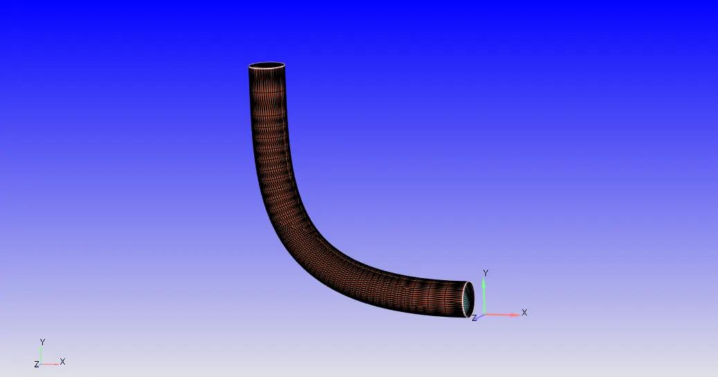
Case setup
Material
Predefined mixture: Air
Species: N2,O2
Boundary conditions
INLET: Inflow BC
Inlet pressure=150000.0 Pa
Outlet: Outflow BC
Oultet presssure=100000.0 Pa
Throttle body: Wall BC
Wall motion type: Rotating
Surface movement: Moving
A rotation rate file is created for giving the angle and time. The rotation center and axis are selected as the axis of the cylinder of the throttle body. And is obtained by measuring arc normal.
Wall: Wall BC
Regions and initialization
Air is added
O2=0.23
N2=0.77
Turbulence modeling: RNG K epsilon
Meshing
Base size=0.002 m
A fixed embedding is added to refine the mesh near the throttle body.
Entry type=Boundary
Boundary id=throttlebody
Mode: Permanent
Scale=3
Embed layers=2
The mesh generated is shown below, Because of the boundary fixed embedding more cells created near the throttle body.
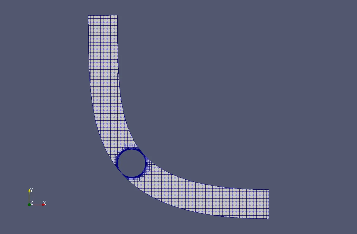
Before running a full hydrodynamic simulation a no hydrodynamic simulation is performed for checking the throttle movement and mesh.
Simulation parameters
Start time=0 s
In order to calculate end time, we need to calculate flow through time.
`time= (l eng th)/(Velocity)`
Velocity at inlet=187 m/s (From steady state results)
length =0.2 m
`time=0.2/187=0.00106s`
The flow-through time is 0.001s in this simulation we are simulating for 10 times the flow-through time so the end time is selected as 0.01s.
Initial timestep=1e-09s
Maximum timestep=1 s
Solver: Transient
Simulation Mode: Full hydrodynamic
Gas flow solver: Compressible
Navier-stokes solver type: Density-based
Output files
The time interval for writing 3D output files=0.0005 s
So the solver writes a 3D output files after every 0.0005 seconds.
Post-processing
Total cell count
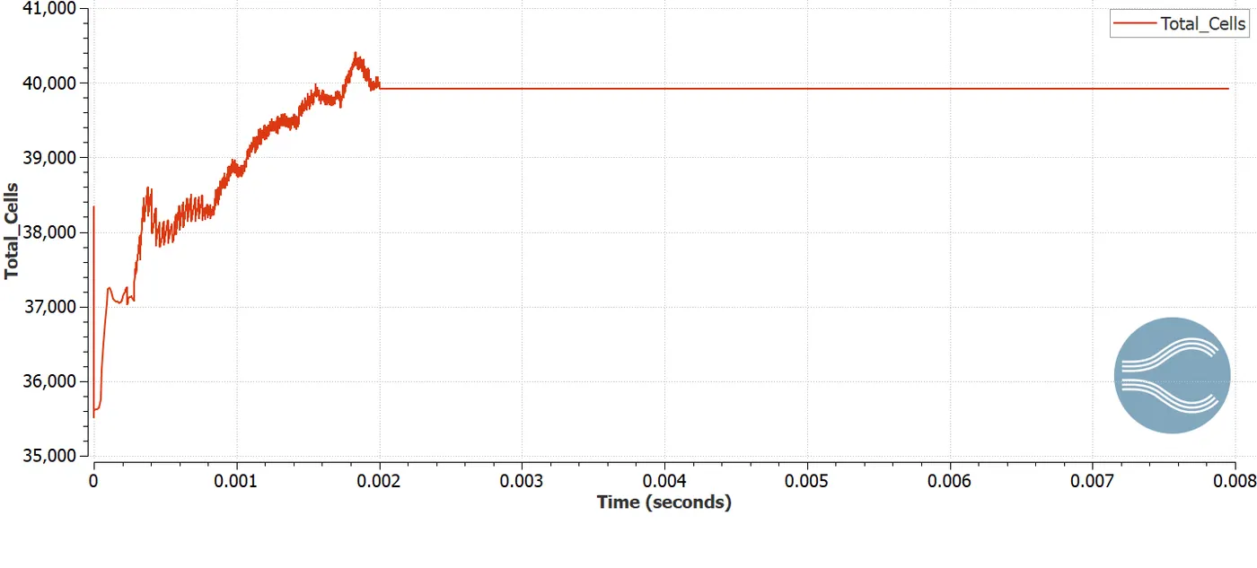
- The total cell count varies up to 0.002 s it is because of the rotation of the throttle body, After 0.002s the throttle body is stationary so the total cell count is constant.
Velocity
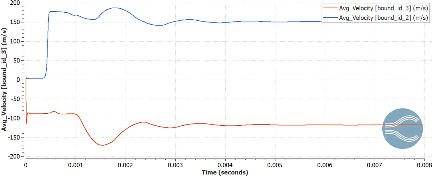
Area average velocity at inlet and outlet is given below,
Velocity contour at last time step.
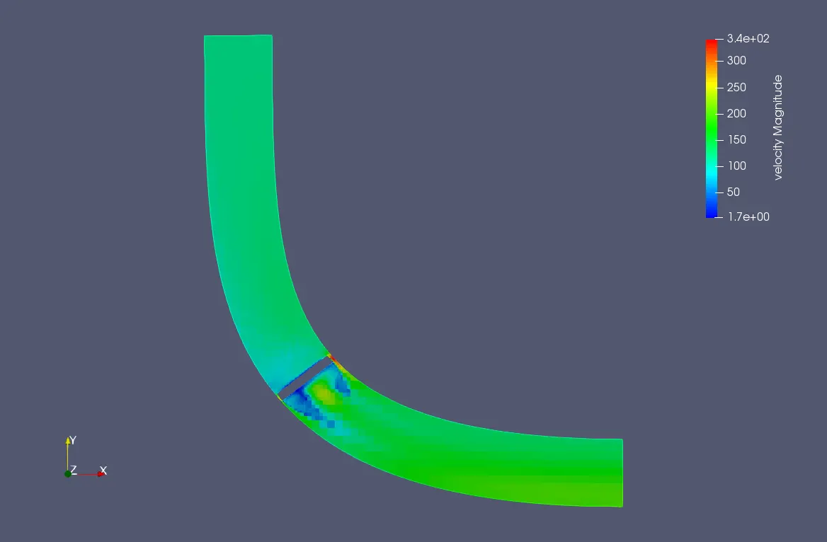
From this, we can see that Velocity near the outlet region is larger than the inlet region, because of the narrow airflow. The velocity value is high in the narrow airflow region.
Velocity animation with time is given below,
Pressure
Pressure contour at cut plane z of last time step.
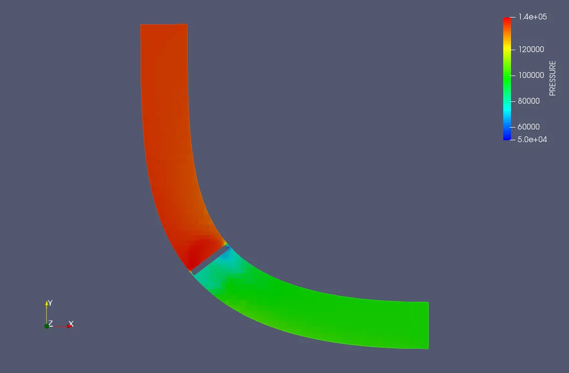
From this, we can see that because of stagnation pressure at the inlet side is higher than the pressure at the outlet.
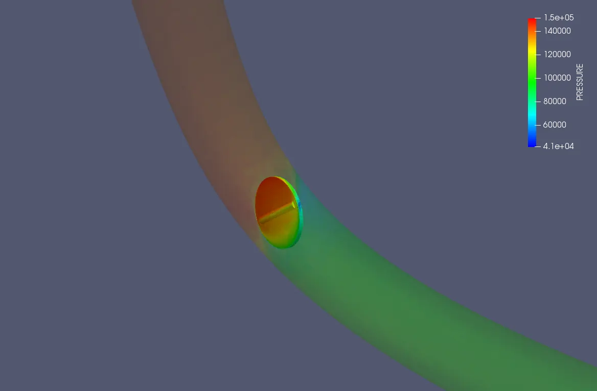
Due to stagnation pressure at the front side of the throttle body is higher than the rear side. And also the pressure at inlet side increases with the angle of rotation. It is shown in the animation below,
Area average mass flow rate
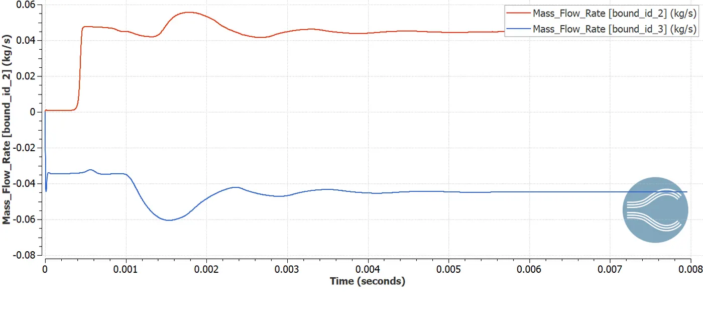
The mass flow rate changes with rotation of the throttle body.
Conclusions
- The presence of the throttle body results in an increase in velocity and a decrease in pressure at the outlet.
- The flow can be controlled by changing the orientation of the throttle body. Pressure, velocity, and mass flow rate at the inlet can be controlled by varying angle of rotation of the throttle body.