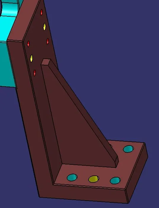
Week 4:- Pin Unit Design Challenge
PIN UNIT DESIGN
OBJECTIVE: To design 2 different types of fixed pin unit and retractable pin unit each with different pins, risers, blade and block.
ABSTRACT: In industry while assembling a car several processes has to be performed
on it at part level so that it is fit for the roads. The process that is performed at the part level can be summarized in one word as joining processes. And to precisely do this operations on a car panel requires the panel to be held properly at the same position so that the robot can work upon it. To hold the panel in position we use various fixtures which is an assembly of various units like rest pin units, fixed pin units, retractable pin units, rough locator units, sensor units, base unit etc. This project focuses on the design of fixed pin unit and retractable pin unit with design considerations which are usually taken into account while making a fixture.
SOFTWARE USED: CATIA-V5
FUNDAMENTALS:
3-2-1 principle: Our ultimate intention for using pin unit is to fix the work piece so that it does not deviate from the position while the operation is being performed on it. For this reason we use 3-2-1 principle.
Every component we know has 6 degrees of freedom. They are listed below:
1. Translational motion along x-axis. 2. Translational motion along y-axis.
3. Translational motion along z-axis.
4. Rotational motion along x-axis.
5. Rotational motion along y-axis.
6. Rotational motion along y-axis.
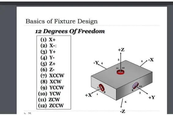
Degrees of freedom can be simply understood as the direction in which any component can move. These 6 degrees becomes 12 if we consider translation along negative and rotation in anti-clockwise direction too. That means, every component can move in all the direction when it is free. But processes like welding, stamping or others and in fact every other cannot be carried out on such free to move body for obvious reasons. Thus the body must be constrained in all the major direction in order for the workman to work upon it. This constrain on motion is achieved by 3-2-1 principle.
In 3-2-1 principle we make use of locating pins in the given order to fix it on a fixture:
- 3 pins are located on the bottom side of the component. These pins constrain the translational motion of the body in z direction and rotational motion along x-axis and y-axis. Thus 3 degrees are restricted. But the body still can rotate along z-axis and translate in x-axis and y-axis.
- 2 pins are located on the back side of the component. These pins constrain the translational motion along x-axis and rotational motion along z-axis. Thus we have constrained 5 degrees in total. But translation along y-axis is still possible.
- 1 pin located on the adjacent side of the 2 pins we can constrain the last degree that is translation along y-axis.
Components of fixed and retractable pin unit:
The components used in both the units are nearly same with just one main difference in retractable pin unit as it uses a cylinder in addition to retract the pin from its initial position. The components for both of them are listed below:
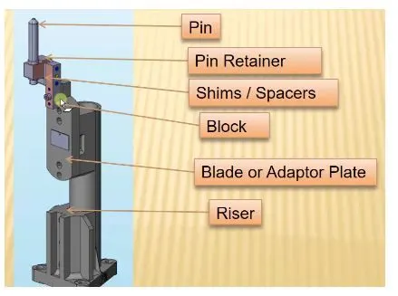
FIXED PIN UNIT:
1. Locating pin
2. Pin retainer
3. Shim pack (2 way adjusting)
4. L-block
5. Blade
6. Riser
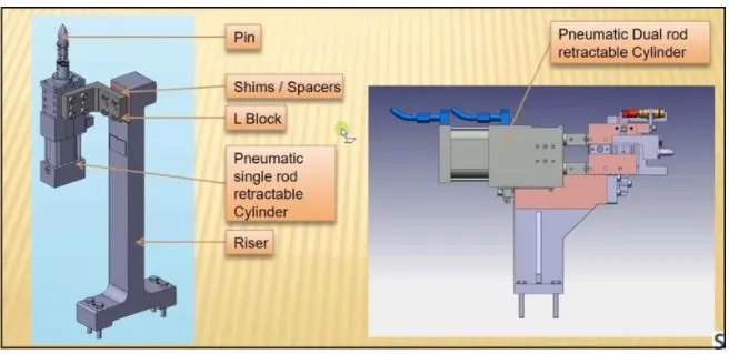
RETRACTABLE PIN UNIT:
1. Locating pin
2. Retainer (optional depending on the cylinder being used)
3. L-block
4. Shim pack
5. Blade (optional depending on the design)
6. Cylinder
7. Riser
Locating pins:
locating pins are used for controlled, fine tolerance positioning of a work piece. For example, a pallet that is moved along one axis, where the drive mechanism is not accurate and stable enough to place it in a position sufficiently accurate to execute a particular process, the use of locating pins may be the best solution. Usually two locating pins are enough to properly locate the work piece on one plane. We should also consider the following points while choosing the locating pins:
1. Pin should engage 3-5mm from car part entry surface.
2. All pins should be accommodated with 2-way adjustable shims irrespective of direction of arresting.
3. Round pins should be used in case of 4-way arresting of car part if the hole is round.
4. Round pins can be used in 2-way arresting of car part if the hole is slotted.
5. Diamond pins should be used in case of 4-way arresting of car part if the hole is slotted.
6. Diamond pins can be used in 2-way arresting of car part if the hole is round.
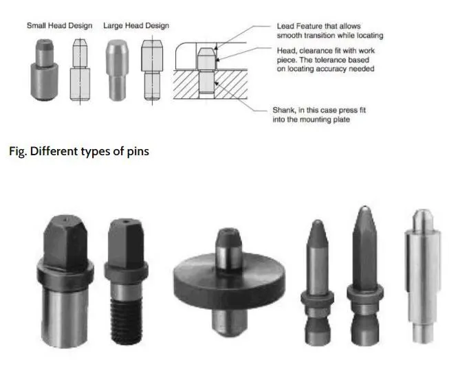
The Diamond Shape is a critical feature that helps with machining inaccuracies and smoother locating operation. When two round head pins are installed onto one plate, the distance between two mounting holes must be extremely precise and even then, the work piece will not be placed on the base as easily as it would with the use of a diamond shape pin.
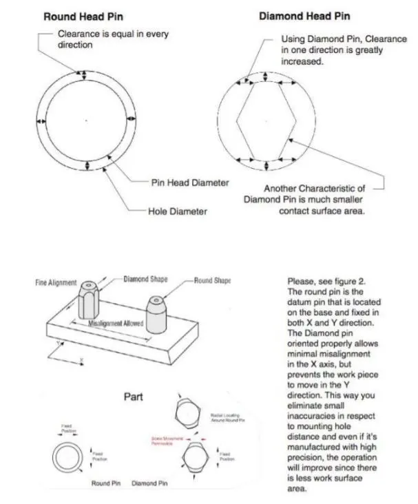
Typically, locating pins are manufactured from hardened tool steel such as 01 heat treated to 60-63Rc or from case hardened carbon steel (1045 with 45-50Rc). In some cases, soft 300 series or hardened 400 stainless is used in assemblies where no rust is accepted. Please, remember that pins made out of soft materials will wear out much faster than harden pins.
There is a variety of coatings that can be chosen based on your application. In corrosive environments, a hard chrome, Dicoat or TICN coatings can help extend the life of the pin since they provide non-corrosive and hard layer that can be as hard as 3000 Vickers. A variety of insulating coatings or materials can be used in case of welding applications, KCF stainless steel coat is one surface treatment that provides great insulation and prevents weld build-up between the work piece and the surface of the pin.
Pin retainer:
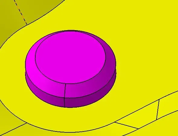
A pin retainer is a part which holds the pin in position. It can either be a make part or a standard part. Pin retainers can be of two types:
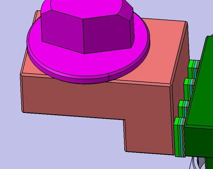
HORIZONTAL PIN RETAINERS: Horizontal pin retainers are used to extend a straight plane with a perpendicular locating pin. These come with either 3 or 4 hole configuration with tapped and untapped hole variations. All the locating pin hole for horizontal pin retainers are 16mm in diameter.
Block/L-block:
1. These parts are mainly used to accommodate the shimming direction as per fundamental in general.
2. In some cases they are used for other design feasibility.
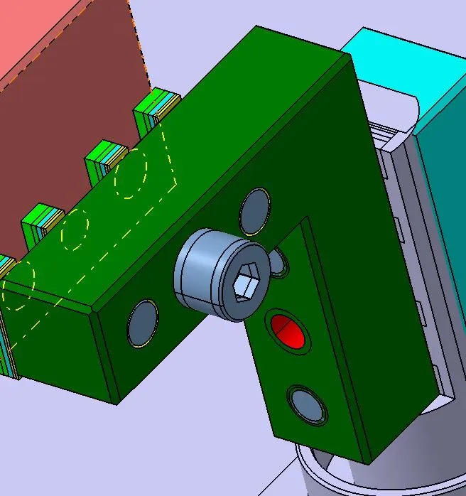
Block/L-block:
1. These parts are mainly used to accommodate the shimming direction as per fundamental in general.
2. In some cases they are used for other design feasibility.
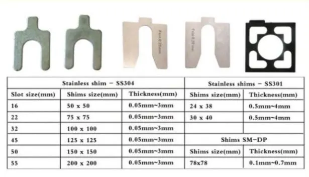
Shim/spacers:
1. These are used to avoid the stacking up of tolerances and thus keeping the locating pin are a proper position.
2. Generally for the Mylar and Locating pin adjustment solid shim pack is used.
3.5 mm shim pack has various option of 0.5mm x2, 1mmx2, 2mmx1 makes shim pack. Shim is of 2 slots/ hole, 3 slots/hole or 4 slots/hole.
Blade:
1. Blades are the plates which are attached to the riser and other components like
cylinder, arm etc are mounted on it.
2. It can either be a standard part or a make part.
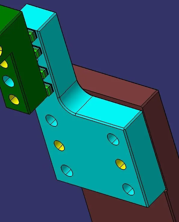
Riser.
1. Riser is a structure generally used to mount the toggle clamp and rest, clamp Mylar and location pin and to give height to the assembly.
2. It is not necessary to have one riser where all the parts of clamp or rest or location units are mounted.
3. Generally risers are either made of plate fabrication or plate and tube welding together or from single gas cut plate.