Week 4 - ICEM Meshing for Fuselage
AIM: To create a domain suitable for the helicopter fuselage geometry using ICEM CFD.
OBJECTIVE:
-
Using ICEM CFD, The domain size is mentioned within the video i.e.
- Element size around the domain
- Prism element size.
SETUP & SOLUTION:
-
Because half domains are symmetrical, they will be created. The symmetry and far-field boundary conditions (for free stream velocity at infinity) will be used. The side face, top face, and bottom face will all be subjected to the far-field boundary condition. While the front face will have an inlet boundary condition, the back face will have an outlet boundary condition.
-
Following flow conditions were considered for the simulation:
- Altitude of 4 km
- Free stream Mach number is 0.3
For meshing:
- Assume Y+ = 30
- Tetra mesh for far-field
- Prism mesh for the boundary layer.
GEOMETRY :
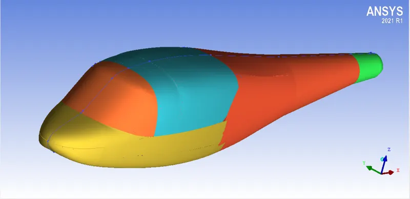
- Given Helicopter Fuselage Geometry;
-
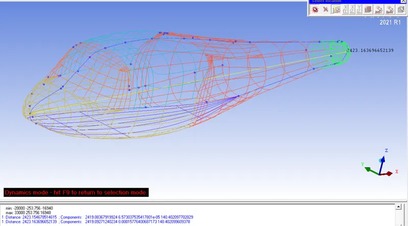
Characteristic Length is measured using the measured distance tool.
- After measuring characteristics length, the domain has been created per the image below.
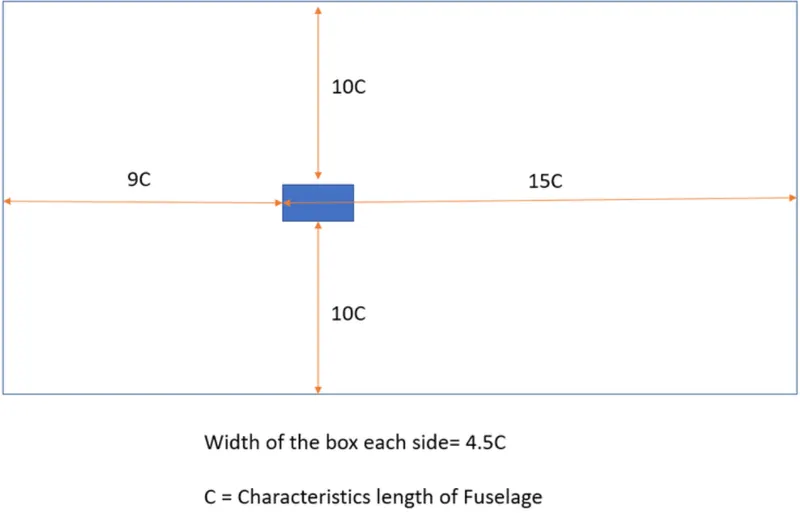
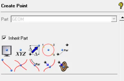
- To create this domain, the first reference point has been made using the point creation tool given in the ICEM user interface. To create a point, the option called base point & delta option has been used. The first point has been made at a distance of 21808.35mm from the front reference point which is shown in the below image. Similarly, the other corner points of the domain have been created. The table following to below image is showing the inputs used to create the domain.
|
INDICATION |
TOTAL LENGTH (mm) |
|
C |
2423.15 |
|
9C |
21808.35 |
|
15C |
36347.25 |
|
10C |
24230.15 |
|
4.5C |
10904.17 |
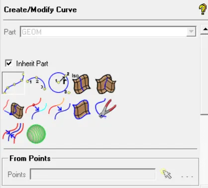
- After creating points all corner points, the lines have been created using the following option called Create/Modify Curve using points.
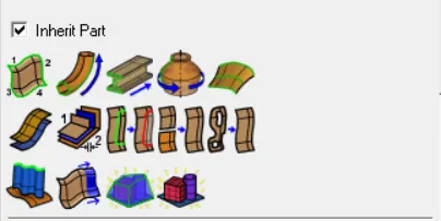
- Next, surfaces have been created using the create/modify surface option using the simple surface method. From 2-4 curves option has been used from the Simple Surface method as shown in the below image.
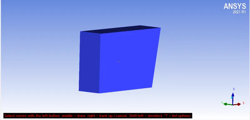
- Following is the domain created after generating surfaces.
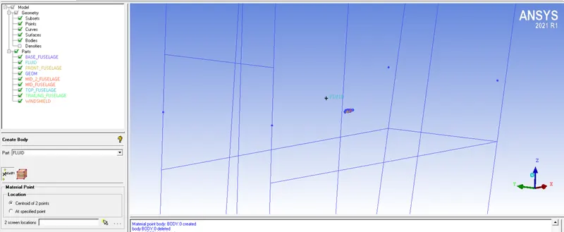
- Now to create the fluid domain, the option called create body has been used which will convert these separate surfaces into one single body as a fluid which is shown in the image next to the below image. In that image, it can be seen as the fluid domain indicated.
- In this fluid domain, the different areas are required to define as per their function like inlet, outlet, symmetry & far field areas. To define them, the option called Create Part has been used. In the below image, the inlet has been created after selecting the front face. In a similar way, other parts were also defined.
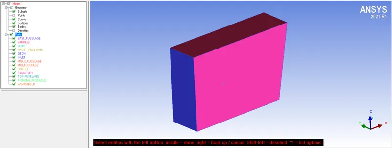
- Right now, the fuselage & fluid domain are two separate entities. And because of that, the solver will not be able to identify the fuselage in the fluid domain. To make define the fuselage as an integral part of the fluid domain, the outer boundary of the fuselage will be trimmed from the fluid domain. To trim the boundary, the option called Segment/Trim Surface option is available in Create/Modify Surface. The "Curve" method has been used in that option. The boundary was trimmed from the symmetry surface.
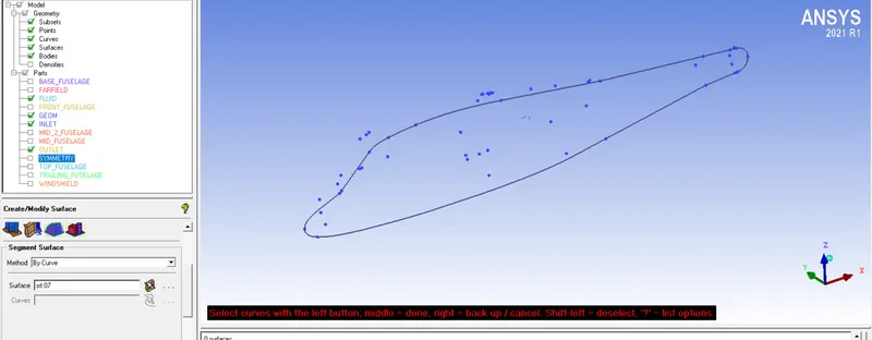
- After trimming from the symmetry surface, the fuselage surface was deleted using the "delete surface" option. The outcome is displayed in the below image.
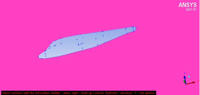
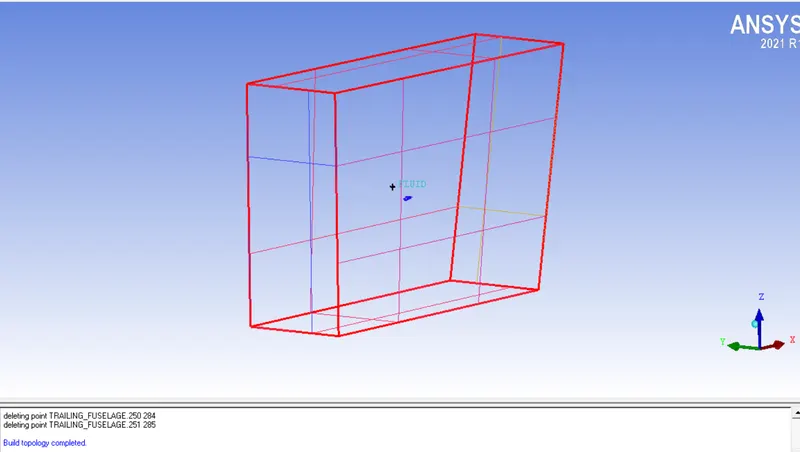
- The final domain geometry was checked for any error using the Repair Geometry option. In that, the option called, Build Diagnostic Topology option is used.
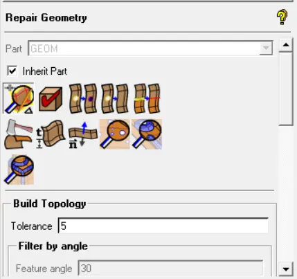
- After applying, the boundary of the fluid domain became red which means there is no error involved in the geometry.
- In the next step, a global mesh setup has been applied before creating a mesh. To set up global mesh parameters, the first four options shown n the Global Mesh Parameters were applied to define the mesh. The first is Global Mesh Size shown below image. The scale factor was kept at 1 & mesh element size was kept at 2048 mm.
- The next option is shell meshing parameters. All options were kept by default.
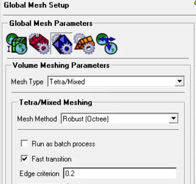
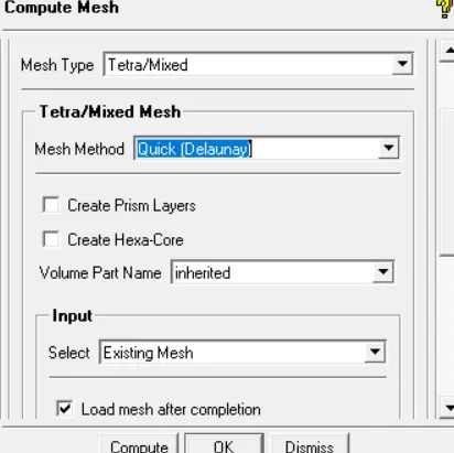
- After that Volume Meshing Parameters was defined for the Tetra/Prism mesh type. The QUICK (Delaunay) mesh method was used to generate mesh because the prism layers are required to create the mesh. This method is not used if the requirement is to generate prism layers.
-
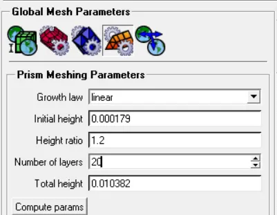
The fourth option is for the prism meshing parameters. In which the layers nearer to the fuselage boundary were created. The Initial height or first layer height & total height for 20 layers were calculated as per below analytical method.
-
The cell height depends on the following two conditions:
1. Type of flow
2. Turbulence model
-
If cell height (y+) has a lower value than the higher resolution mesh & longer the solution time & vice versa.
-
To calculate initial cell height, the following formula was used.
y+=ρUΔyμ">y+=ρUΔyμy+=ρUΔyμ
-
To implement this equation, the required inputs need to be calculated.
-
As per ISA, since the height is within 4 km, the lapse rate can be assumed as -6.5.
-
Temperature, T = 288.15 - 6.5 X 4 = 262.15 K
-
Speed of sound, a=γRT">a=√γRTa=γRT = sqrt(1.4 X 287 X 262.15) = 324.52 m/s
-
Free stream velocity, v = Mach Number X a = 0.3 X 324.52 = 97.36 m/s
-
According to ISA, Density, ρ=ρ0(ThT0)4.25">ρ=ρ0(ThT0)4.25ρ=ρ0(ThT0)4.25 = 1.225(262.15288.15)4.25">1.225(262.15288.15)4.251.225(262.15288.15)4.25 = 0.8195 kg/m^3
-
Viscosity, using Sutherland's law, μ=1.458⋅10-5⋅T1.5T+110.4">μ=1.458⋅10−5⋅T1.5T+110.4μ=1.458⋅10-5⋅T1.5T+110.4 = 1.661 X 10^-5 kg/ms
-
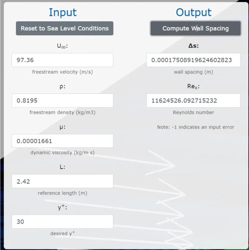
The first cell height has been calculated using the online y+ calculator provided by Pointwise. The result is as follows:
-
Now to calculate the boundary layer height, the following formula has been used.
-
δ=5⋅CRe">δ=5⋅C√Reδ=5⋅CRe = (5 X 2.422) / sqrt(11.6 X 10^6) = 3.556 X 10^-3 m
-
To calculate the number of layers in the boundary layers = boundary layer height/ first cell height = 19.86
-
The calculated values have been inserted into the Prism Meshing parameters dialogue box.
-
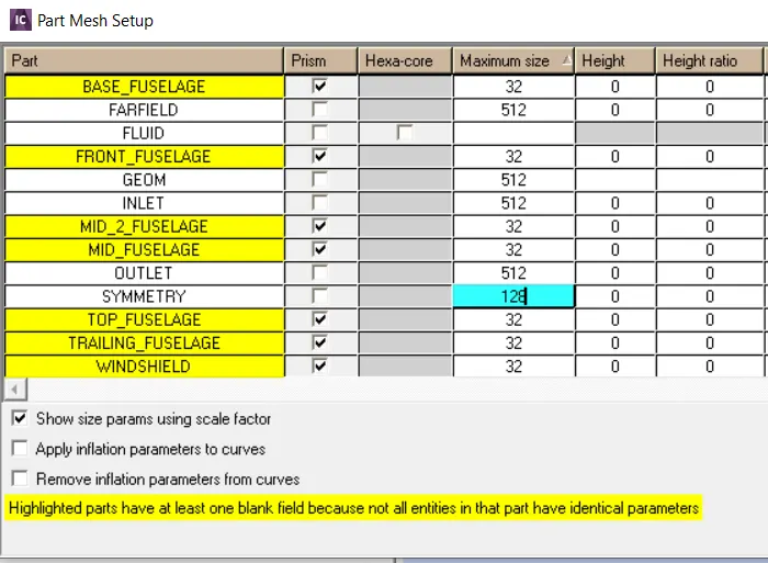
After applying mesh parameters, the different mesh element lengths were assigned to the different parts of the fluid domain. 32mm element length has been assigned to the parts of the fuselage while 512mm is assigned to the fluid domain parts.
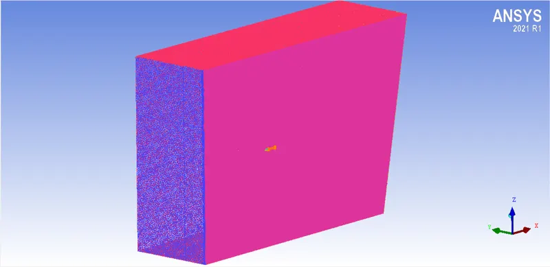
- The following image shows the generated mesh on the fluid domain.
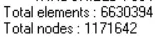
- The details of the generated mesh is as follows:
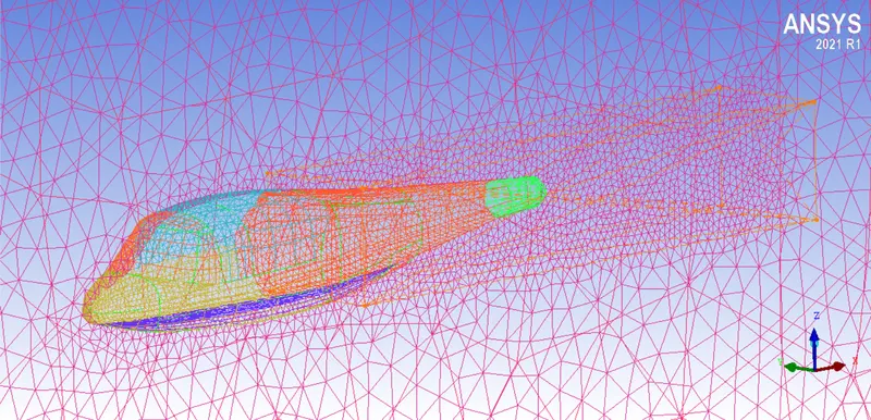
- The mesh generated inside the density zone is shown below image. The elements are very fine compared to the surroundings.
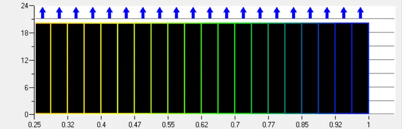
- Quality: For tetrahedral elements, it should be above 0.3 while for quadrupedal, above 0.4.
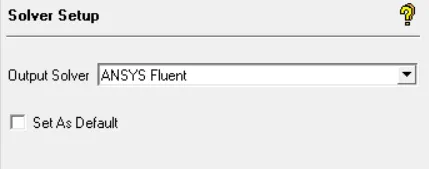
- Output solver as follows:
CONCLUSION:
- Hence the domain suitable for the helicopter fuselage geometry using ICEM CFD has been created.