Week - 4 - Crash Box Simulation
Aim: To simulate the crash test for a given crash box and find the stress, strain, Acceleration, and energy plots and comparing the parameters with changing the thickness( 1.2 and 1.5).
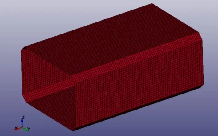
- The given crash box has meshed with shell elements
Procedure:
- First, we have to create a rigid wall for that we have to go to the *keyword file by creating the rigid wall type is planar then we have to N1-N2 method by selecting the two nodes normal to the rigid wall.
- Then we have to specify the distance from the crash box to the rigid wall to observe the impact.
- Here the direction of the rigid wall normal will be opposite to the velocity direction.
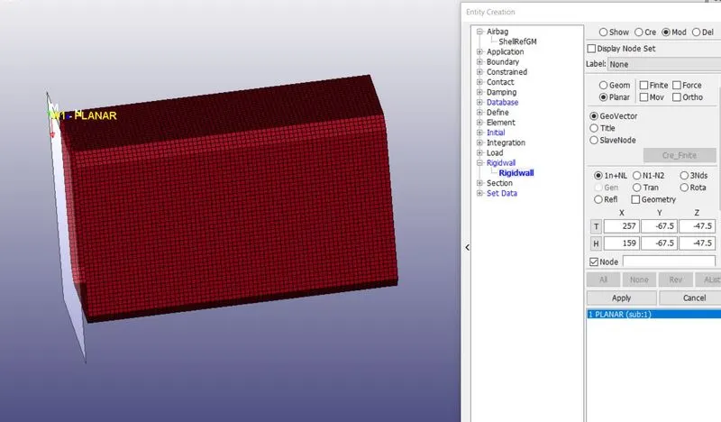
Fig:2 Rigid Wall Creation
Creating the material and section Cards:
- Now we have to create the section cards, material cards for the part, for that goto create entity >section>select the shell there we have to enter the SecID and Thickness is 1.2.
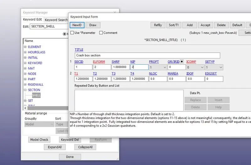
Fig:3 Assigning the shell card with a thickness
- Here we assumed the material of the crash box is steel so we have to select the Piecewise_linear_Plasticity to undergo the plastic state.
- Here we are following the gm-mm-ms unit system
- Density=0.007750 `(gm)/(mm)^3`
- Young's Modulus=21000 `(gm)/((mm)*(mm)^2`
- Poision's ratio=0.33
- Yield Stress=250 `(gm)/((mm)*(mm)^2`
- Tanget Modulus=2100 `(gm)/((mm)*(mm)^2`
- Here Tangent Modulus is 1% of the young's modulus.
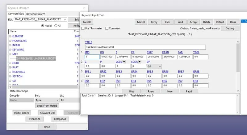
Fig:4 Material property definition Piecewise_linear_Plasticity
- Then define the material and section properties to the part as shown in the below image.
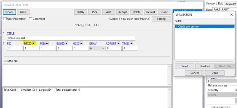
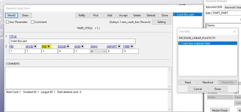
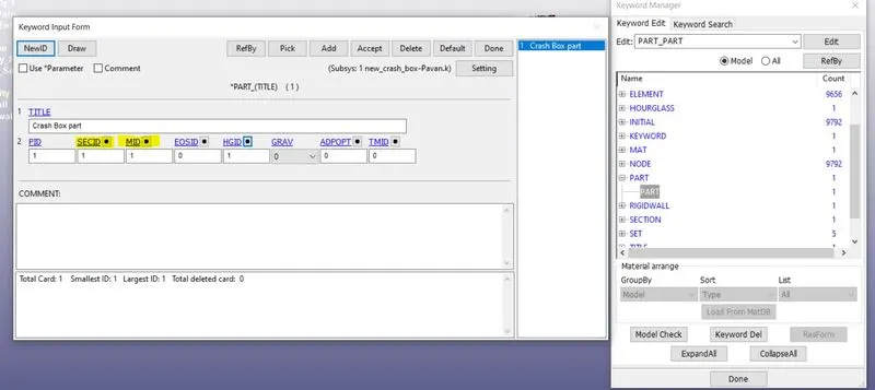
Fig:5 Defining the Sec_ID and Mat_ID to the part
Defining the Initial Velocity(50kmph):
- For creating the initial velocity goto Entity creation>select the velocity >then pic all nodes by area then enter the value of velocity (13.88 mm/ms) as shown below image.
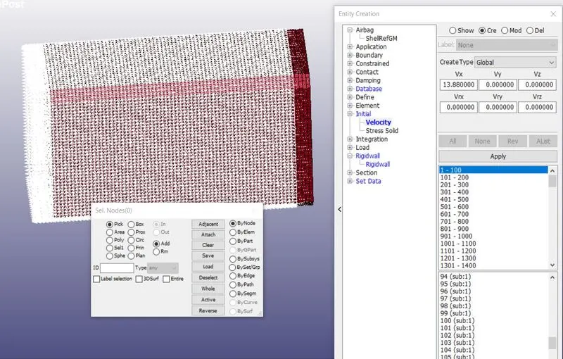
Fig:6 Defining the Initial velocity
Defining the Contact Interface:
- Here contact definition is an important factor, For this analysis, we are defining the automatic single surface contact as shown below image.
- This contact also involves the self contact here no need to select the master surface slave surface is enough to define the contact.
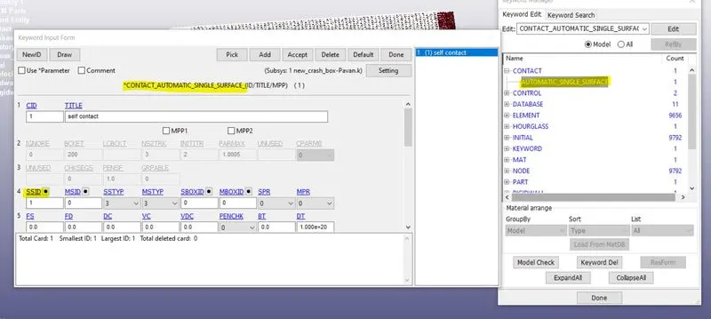
Fig:7 Automatic single surface Contact
Creating the cross-section:
- Here we have to create the cross-section for observing the cross-sectional forces along the axis of the tube for that we have to create a specific node list and element list to define the cross-section.
- This node list and element list can be created by using the create entity option by picking the nodes and corresponding elements as shown in the below image.
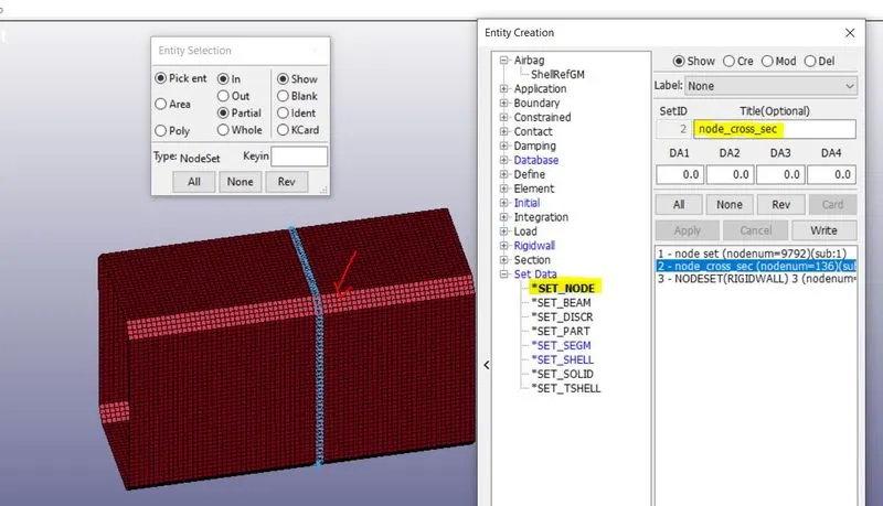
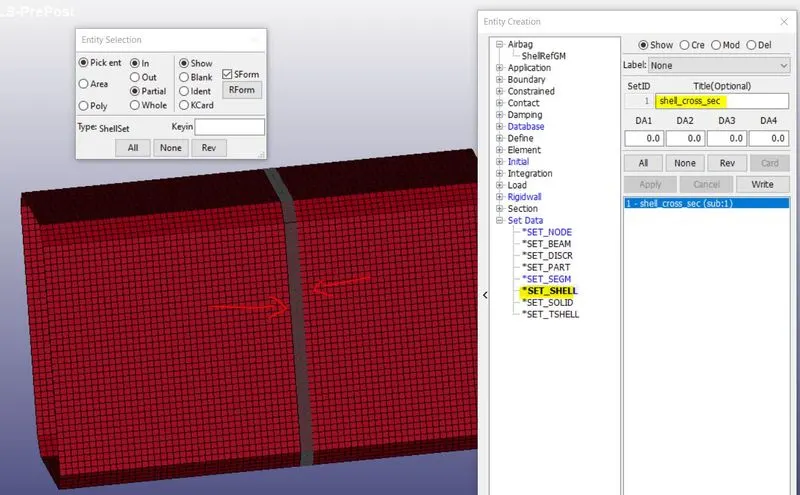
Fig:7(A) Node list Fig:7(B) Element list
- In this analysis, we need the stress-strain, acceleration, and energy values at nodes, sections, and over the whole body.
- Termination time is assigned by using *keyword control-termination card(here we are given the 1ms).
- *control energy is also used to calculate the energy dissipation, hourglass energy rigid wall energy, sliding interface energy can be Calculated by this card.
- Then output data is generated by using the *DATA_BASE_KEYWORD there are like Binary-D3 plot, ASCII option(Elout_element data, GLSTAT-global statics, and energies, etc, MATSUM-part energies, NOD OUT-nodal motions, RCFORC-resultant contact interface forces, SLE OUT-contact interface energies, etc) are assigned for the generating output data.
- For getting the acceleration plot of a node in the middle of the crash box by *DATABASE_HISTORY_node card.
- *DATA_BASE_CROSS_SECTION_SET Card is used to defines the cross-section for resultant forces written in ASCII file SECFORC.
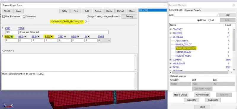
Fig:8 Cross-section set
- Here we have to run the model for both shell thickness(1.2mm and 1.5mm).
- After all required cards assigned to the model once check the modal check if there any errors, if there are no errors then save the keyword in the different folder and run the simulation by going to Ls-run loading their keyword file.
Results and Discussions:
- After simulation open the Binary D3 plot for output results and it will give the animation of the deformed body and various other parameters.
Cross-Sectional Force:
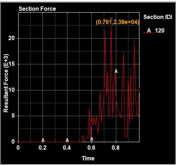
Fig:9(a) cross-section Resultant force for shell thickness(1.2mm)
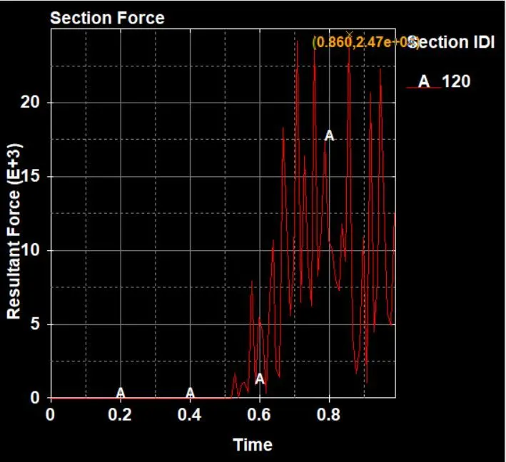
Fig:9(b) cross-section Resultant force for shell thickness(1.5mm)
- If we observe the above two plot fig(9(a)) and fig(9(b)) the resultant cross-sectional force in the middle of the crash box for 1.5mm shell thickness is higher(`24.7*10^3 N`) than the 1.2mm shell thickness(`23.8*10^3 N`) . This is because of the 1.5mm shell thickness having an extra mass compared to the 1.2mm shell thickness. so extra mass is responsible for producing extra force values.
Acceleration of node in the middle of the crash box:
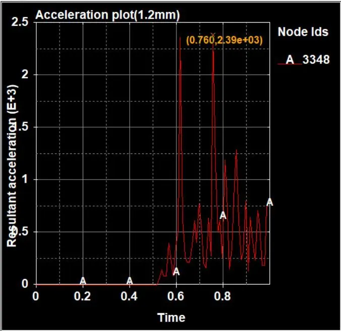
Fig:10(a) Acceleration of a node in the middle (1.2mmThickness)
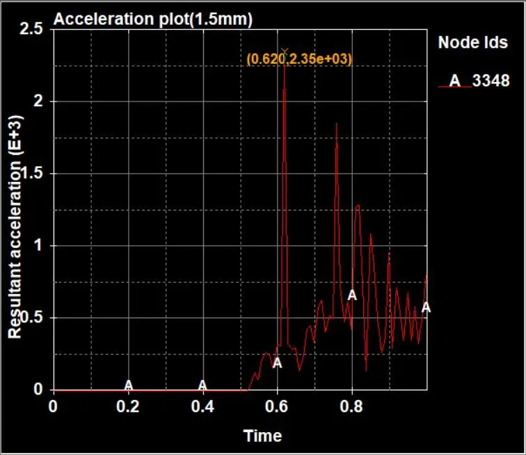
Fig:10(b) Acceleration of a node in the middle (1.5mmThickness)
- If we observe the above two plots fig(10(a)) and fig(10(b)) the nodal Acceleration values for both the shell thickness showing identical behavior. shell thickness (1.2mm) requires more time to obtain peak acceleration than shell thickness(1.5mm).
Energy Plots for the crash box:
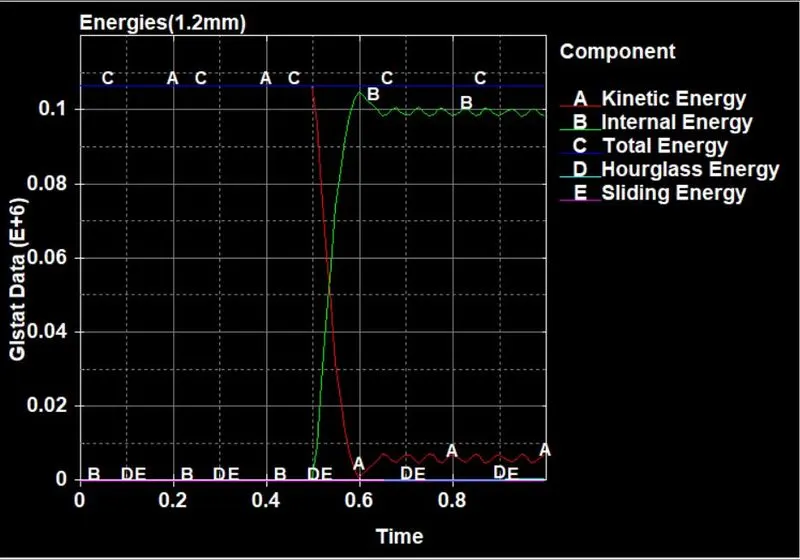
Fig:11(a) Energy plots for the 1.2mm shell thickness
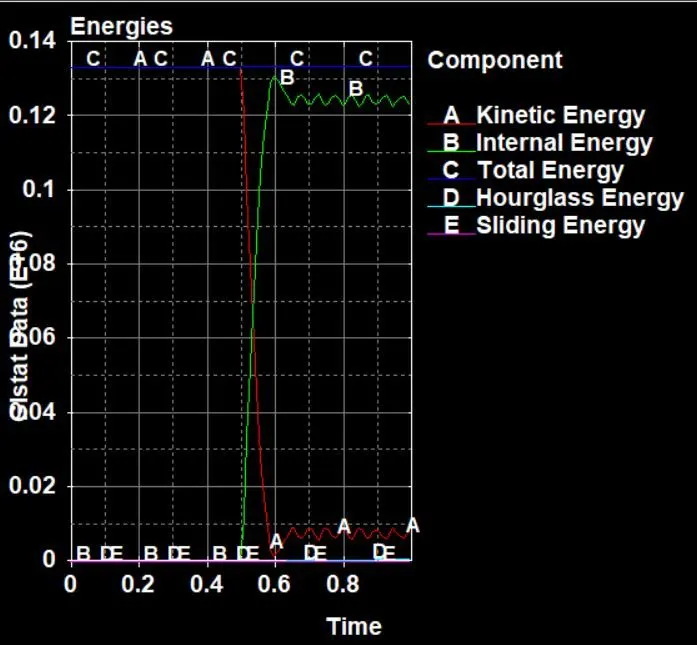
Fig:11(b) Energy plots for the 1.5mm shell thickness
- From fig(11a) and fig(11b), it's clear the shell thickness with a 1.5mm crash box possesses higher energies than thickness with 1.2mm . In both cases, velocity is the same but the mass is different, so the crash box of higher mass having the higher momentum and energies.
- The crash box having the initial velocity which possesses kinetic energy, this kinetic energy is reduced during impact and converted to internal energy.
- If we observe there a small increase in kinetic energy and a decrease in internal energy after 0.6mm because after hitting the rigid wall bouncing back it will attain a small velocity.
- Total energy remains constant because there is no loss or gains energy.
- Hourglass energy is very small compared to internal energy it is an acceptable range.
- Sliding energy is the sum of slave and master energy. But the RCFORC which is an ASCII file and calculates the contact forces for slave and master does not return anything for single surface contact definition. because they're only the slave side is defined for the single surface contact definition and the master side is undefined. so force for slave side is present and thus the net force is zero. so sliding energy for both the cases is zero.
Effective Stress Plot:
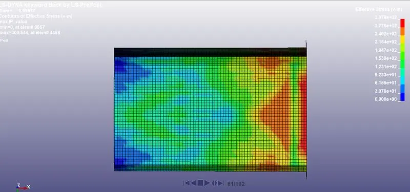
Fig:12(a) Effective stress for 1.2mm Shell thickness
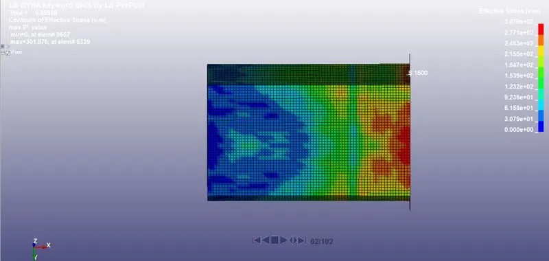
Fig:12(b) Effective stress for 1.5mm Shell thickness
- Fig 12(a) and 12(b) show the max effective stress or von-mises on both 1.2mm shells and 1.5mm shells.
- The highest effective stress for 1.2mm shell thickness is 307.8Mpa and for 1.5mm shell thickness is 307.9Mpa.
- Here we can see the stress value exceeds the yield stress(250Mpa) in both cases. This signifies that the material stress has passed the yield stress and there is permanent deformation enters into the plastic stage.
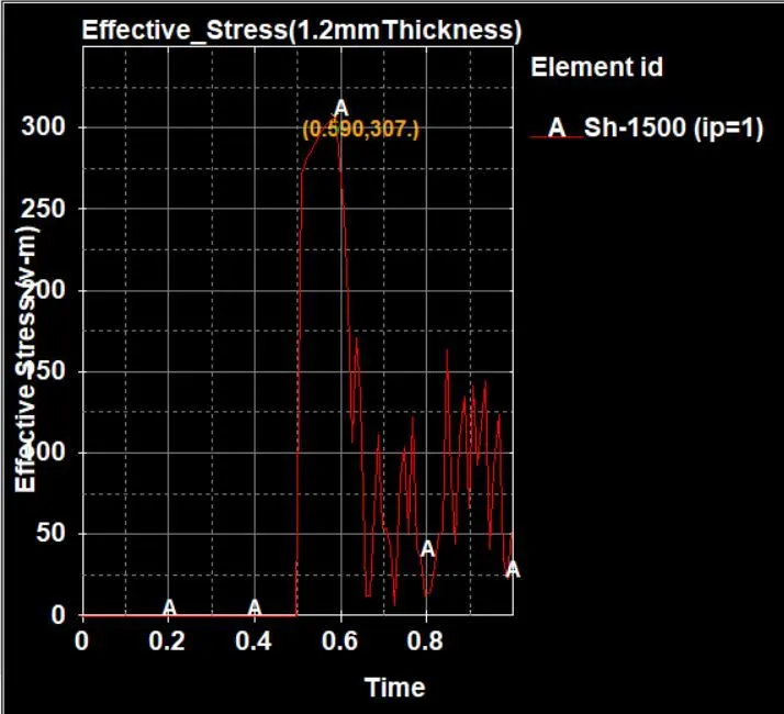
Fig:13(a) Effective stress at element no:1500 in 1.2mm shell thickness
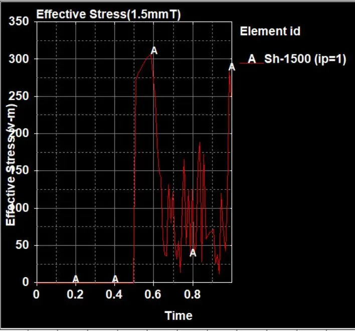
Fig:13(b) Effective stress at element no:1500 in 1.5mm shell thickness
Effective plastic strain:
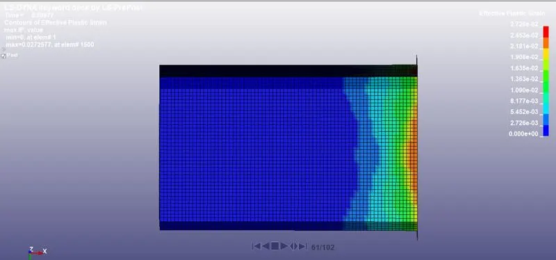
Fig:14(a) Effective plastic strain for shell 1.2mm
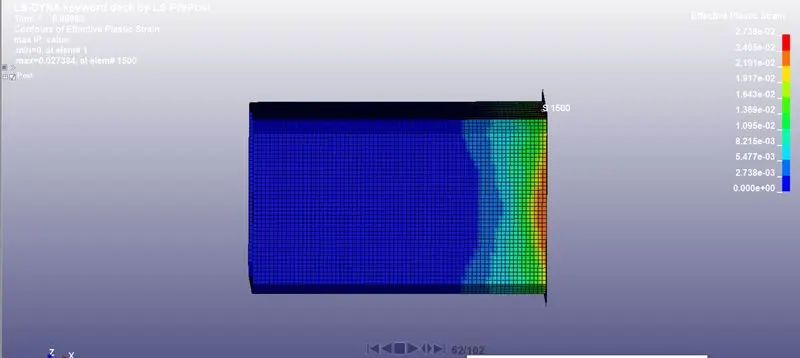
Fig:14(b) Effective plastic strain for shell 1.5mm
- Fig 14(a) and 14(b) show the max effective plastic strain on both 1.2mm shells and 1.5mm shells.
- We can see there is a permanent deformation due to higher stress values greater than the yield stress.
- This plastic strain is developed to the impact as shown in the below animation.
- The plastic strain value 0.02723 for 1.2mm shell and 0.02738 for 1.5mm shell thickness.
- The deformation is not recoverable we can see from fig 15(a) and 15(b) below.
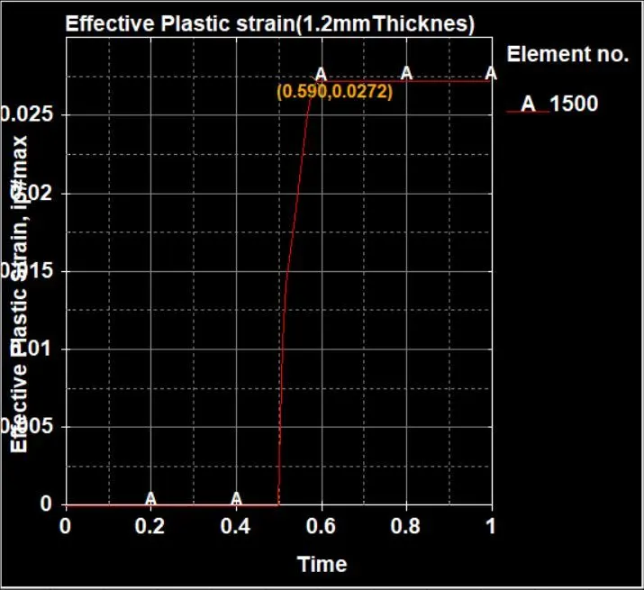
Fig:15(a) Effective plastic strain for shell 1.2mm element no:1500
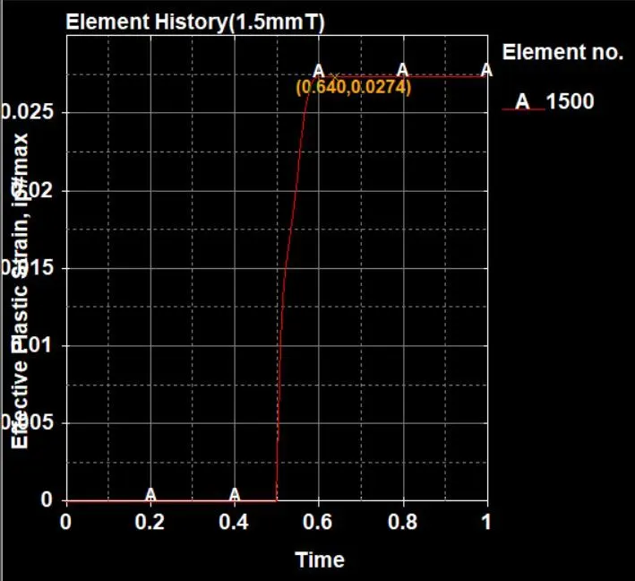
Fig:15(b) Effective plastic strain for shell 1.5mm element no:1500
Animation Links:
Crash Tube for 1.2mm thickness:https://youtu.be/ZcapmCND5K4
Crash Tube for 1.5mm thickness: https://youtu.be/7KTuroQSVx4
Crash Tube Crush:https://youtu.be/wuqv9d09x54
Conclusion: The crash box test has been simulated with considered material properties, required parameters.