Week - 4 - crash box simulation
Objective
To perform a simulation between a crash box and a rigid wall and to derive the requested outputs.
- Crash box is a tube shape object, which is located between bumper and chassis. Its an important component in automobiles whilch helps to reduce the impacts energy during the collision. During the impact, the shock energy is converted into strain energy or internal energy because of the crumpling of the box. It plays a vital role for the safety of vehicle and the reducation of the repair cost when vehicle meet the low speed collision.
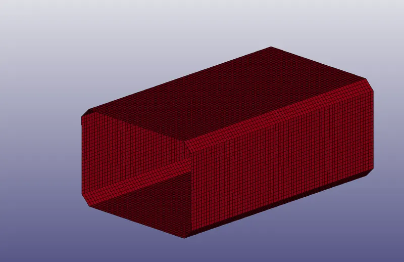
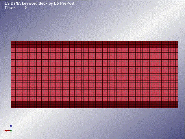
- In this assignment the simulation is performed to simulate a crash test of a crash box which mesh is given. A full-fledges crashbox is a highly sophisticated design but in this case we will go with a rectuangular channel which can thought of as the most simple crashbox. The unit system followed for this analysis is g/mm/ms. Once the simulation is completed and results for the required outputs are collected. Another simulation is runned by increasing the thickness of the crashbox from 1.2 to 1.5mm.
Procedure
- The given model is imported onto the workpage of the LS-Pre-post using File>Open>LS DYNA Keyword file.
Creating a Rigid wall.
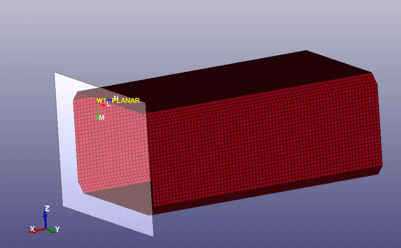
- The given model does not contain any rigid wall needed for the analysis. A new rigid wall is been created using Create Entity> Rigid Wall.
- Here a planar wall is created by defining a vector with one point and a normal. The rigid wall is then offseted to a distance of 10mm from the crash box part.
- It should be noted that the normal created by the rigid wall and the velocity of the crash box should be in an opposite direction. If its been in the same direction the crash box gets penetrated through the wall resulting a wrong simulation.
- Since the generated rigid wall and direction of velocity were in same direction, The normal is made opposite to each other by using the rotate command and specifying the angle and axis its to be aligned.
Assigning material and section to the parts.
- Materials can be classified as elastic materials, elastic plastic materials, hyper elastic materials, viscoelastic materials etc, in which metals and plastics can be modelled using elastic plastic material and is assigned using *MAT_024 (PIECEWISE_LINEAR_PLASTICITY) card from the keyword manager. If failure mode is highly complex or the material is a polymer, composite, thermoplastic, then *MAT_187 card can be used.
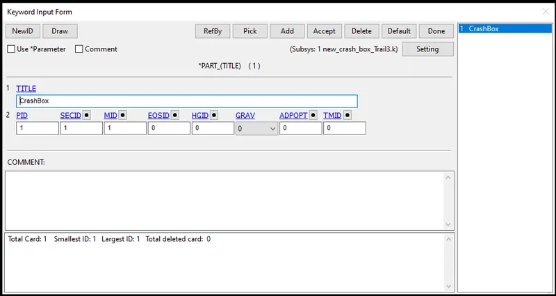
- Here the material for the Crash Box is given as steel and the propeties such as mass density, youngs modulus, poissons ratio, tangent modulus etc were assigned to the material card. Tangent modulus ( Slope of stress strain curve) is taken as 2% of the Youngs modulus.
- A section id with shell card is created for the part with (ELFORM=2) using Keyword manager>All>Section>Shell and a thickness of 1.2mm is assigined.
- Now these created material id and section id are assigned to the crash box part using the part option under keyword manager.
Assigning velocity to Crash Box.
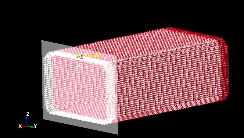
- Before assigning the velocity to the the Crash Box a node set containing all the nodes of the Crash Box has to be created. This can be done using create entity option or by set option under keyword manager.
- The distance between the Crash Box and Rigid Wall is around 10mm and with a initial velocity of 13.88mm/ms the impact should happen at t=0.7ms.
- The velocity is assigned from the *INITIAL _VELOCITY card under keyword manager and a velocity of 13.88mm/ms is assigened in X direction.
Giving contact definition.
- Contact in LS DYNA is defined using contact surfaces and occurs when one surface of the outer surface of a model penetrates another segment.
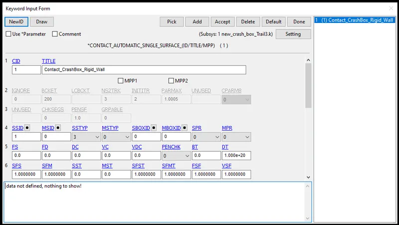
- Here an *AUTOMATIC_SINGLE_SURFACE card from keyword manager is been used and Slave segment set ID (SSID) for the crash box is assigned to the card leaving the MSID blank.
Creating Set data of nodes and elements.
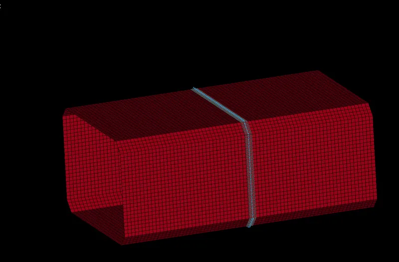
- A set of nodes an elements are created at the middle part of the crash box in order to find out the cross sectional force (SECFORCE), Acceleration of the node etc at the middle part along its lenght.
- These sets can be created using Create entity> Set Data.
Assigning termination time.
- *CONTROL_TERMINATION_CARD from keyword manager is used to define the simulation time using ENDTIME otpion.
- Since the crash box hits the rigid wall with a velocity of 13.88mm/ms and the impact happens at 0.7ms. therefore the ENDTIME is assigned as 1ms (Additional time after the impact is added to get the crash, bouncing, buckling effect etc).
Database.
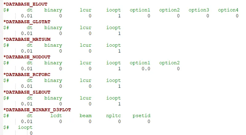
- The oputput data needed for the analysis is generated using *DATABASE card.
- DATABASE_BINARY_D3PLOT under keyword manager ensures d3plot files are written in which it stores the stress strain contours of the deformed system.
- ASCII under keyword manager can generate different output such as force generated in a contact, total energy, material engery etc. Here output for ELOUT, GLSTAT, MATSUM, RCFORCE, NODOUT, SLEOUT are been requested.
- DT (Time intervel between the output) is an essential parameter which basically denotes the time intervel after which the state of solution need to be written and the value is kept as 0.01 for this analysis.
- *DATA_BASE_CROSS_SETION card can be used to generate the section force by assigning the NSID and SSID accordingly.
- *DATABASE_HISTORY_NODE card was also created to get the acceleration plot of a node in the middle of a crash box.
- *DATABASE_EXTENT_BINARY card was provided by specifying STRFLG which write strain tensor data to d3plot and elout.
Model check up and running the simulation.
- The model is checked for any errors and if any error occurs it should be corrected further.
- The .k file is been saved and runned using LS-DYNA manager. If Normal termination is showed after running the file, its then ready to do post processing.
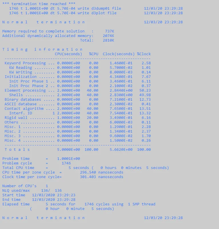
The same .k file created for the shell thickness 1.2mm can be edited to perform the simulation of the crash box with 1.5mm shell thickness. This can be done by editing it in Notepad+ or using LS Prepost.
Results
- Simulation for the crashing of crash box to the rigid wall has been completed and results for the required outputs are collected. Another simulation was also runned by increasing the thickness of the crashbox from 1.2 to 1.5mm and compared the results.
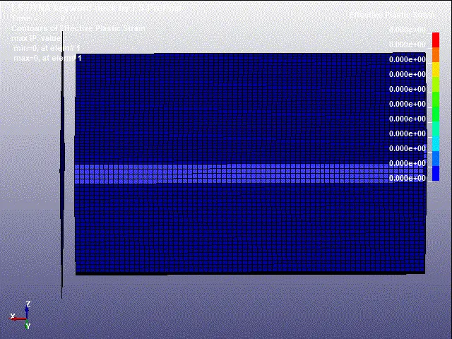
Animation of the final simulation
Cross-sectional force generated in the middle of the crashbox.
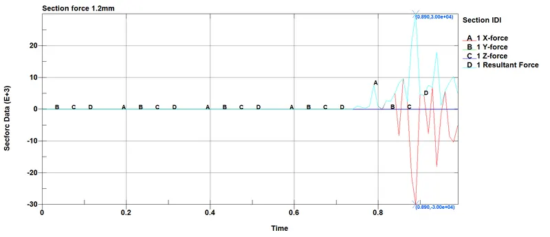
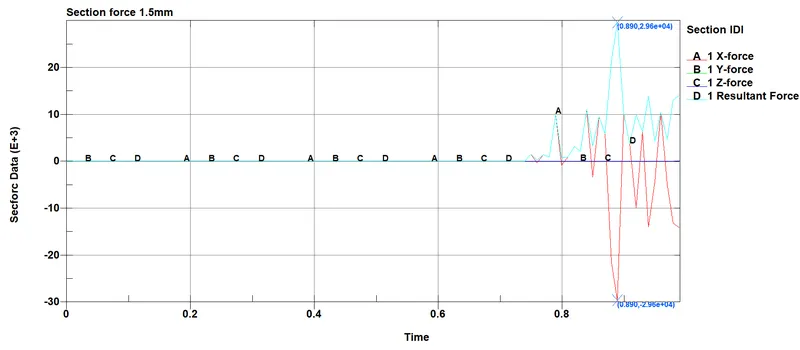
- The above plots shows the magnitude of secforce of crash box for both the thickness with respect to time.
- The magnitude of the force along X-direction is larger compared to other two Y and Z direction, Since the motion of the crash box is along the X- Axis.
- The resultant force for the shell thickness 1.5mm is found to be maximum compared to the one which has the shell thickness of 1.2mm.
Acceleration plot of a node in the middle of the crashbox.
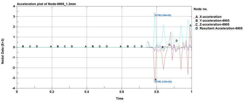
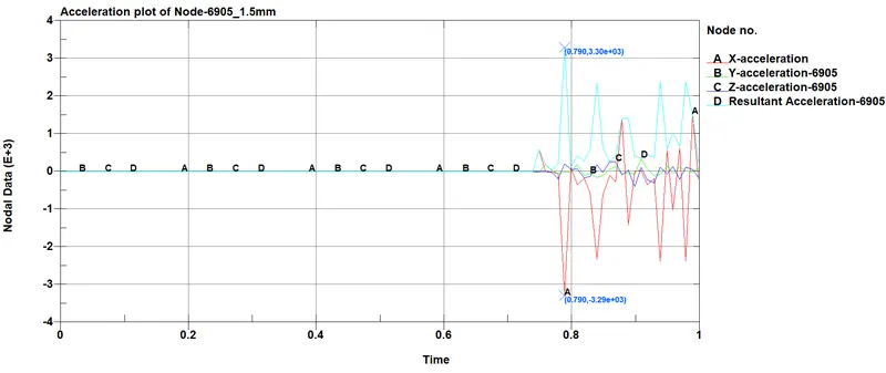
- The above plot shows the acceleration of Node-6905 along X,Y,Z direction and also the resultant acceleration with respect to time.
- The crash box intially moves with a constant velocity and when it crashes the rigid wall its starts deaccelerating. The magnitude of the acceleration in Y and Z axis is very small and the acceleration along X- axis for 1.2mm section is found to be -3.23e+03 `(mm)/(ms^2)` and for that of 1.5mm thickness is -3.29e+03 `(mm)/(ms^2)` which is found to be higher in magnitude when compared to shell thickness with 1.2mm.
Stress-strain plots.
Effective stress(v-m).
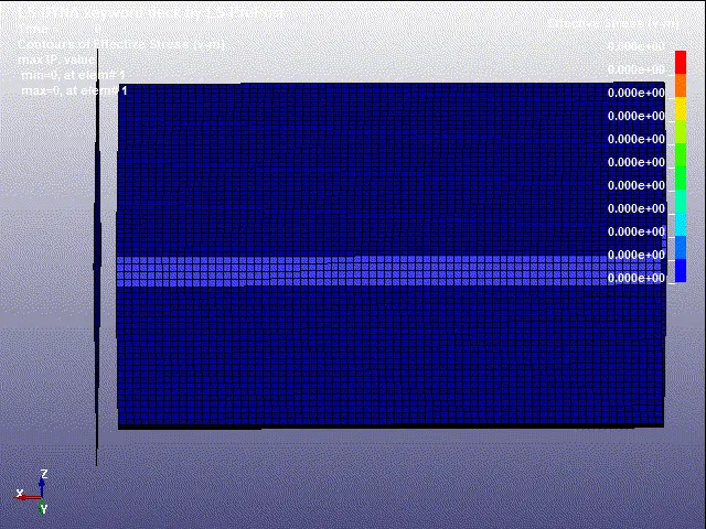
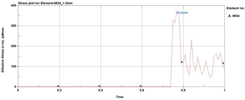
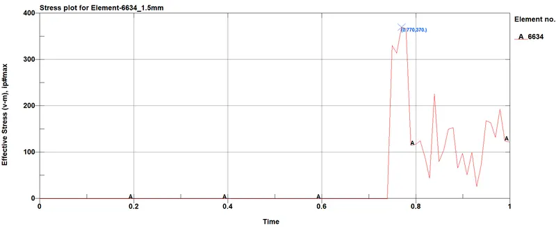
- Von Mises is a theoretical measure of stress used to estimate yield failure criteria in ductile materials and is also popular in fatigue strength calculations (where it is signed positive or negative according to the dominant Principal stress), whilst Principal stress is a more "real" and directly measurable stress.
- Here the stress plot remains same for both the cases and it can be seen that the stress rises to 370 MPa which means after the impact the crash box yields and undergo plastic deformation.
Effective plastic strain.
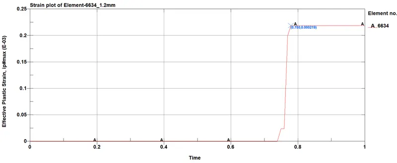
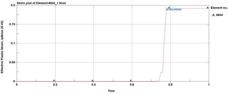
- From the plot it can be seen that the strain curve attains a peak value and become constant. Its due to the plastic deformation occuring in the crash box when its crashes the rigid wall.
- The stain value is found to be more in crash box with shell thickness 1.2mm compared to 1.5mm shell thickness.
Maximum directional stress on the Element-6634 along X,Y,Z direction.
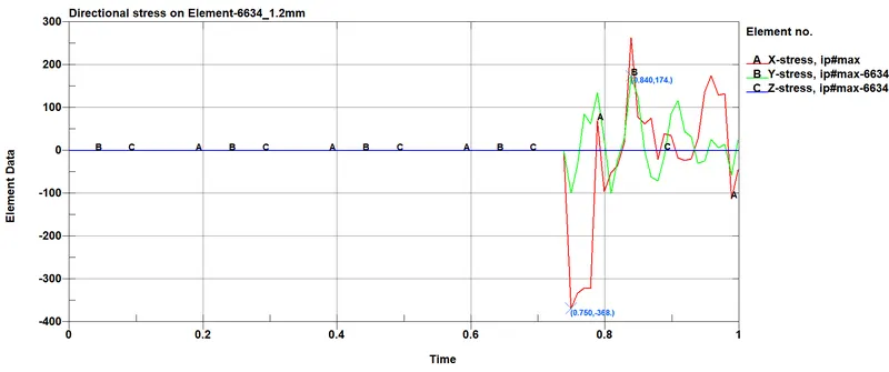
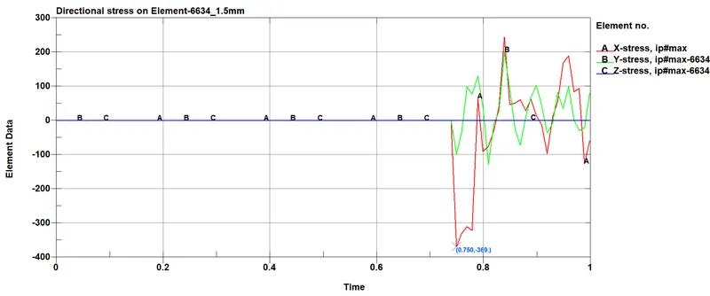
- The directional stress along X,Y and z direction is been plotted and found to be almost similar for both the shell thickness and the stresses are developed in X and Y directions respectively where the magnitude of the stress along the X axis is more and is found to have a maximum value of 369 MPa. The stress developed in Z direction is almost equal to zero.
Maximum directional strain on the Element-6634 along X,Y,Z direction.
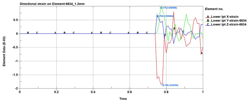
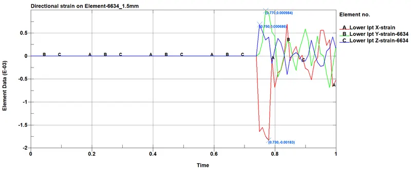
- From the plot its can be seen that there are strains along X, Y and Z axis respecticely in which the strain along X axis large when compared to other two. Also the is only minute change in the value of strain between the crash box with 1.2mm amd 1.5mm shell thickness.
Energy plots for the crash box
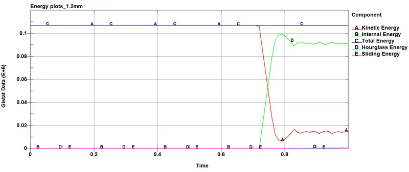
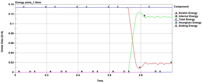
- From the plot, its clear that the shell thickness 1.5mm has higher energies when compared to the shell thickness 1.2mm. Its due to the more mass occupied by the shell with 1.5mm thickness.
- The plot for the Kinetic energy is constant for some time since the crash box moves with a constant velocity and when it crashes it deaccelerates and kinetic energy of the crash box decreases which is shown by a decline curve in the plot.
- Internal energy of the crash box shows a steep increase after the crash happens. Here the kinetic energy has been stored as internal energy following the law of conservation of energy theory.
- Total energy remains constant.
- Hourglassing is a state of strain, which is free of energy (ZEM: Zero Energy Mode) and can emerge in case of one-point-integrated solid- (hexahedrons) and shell elements. Hourglass modes are mostly caused by concentrated loads and contact (contact force at several nodes ). Hourglassing can be reduced by refining the mesh, Using a fully integrated element type etc. but takes more computation time when fully integrated element type is used.
- Here the hourglass energy is very small and is kept with in the range.
- Sliding energy (GLSTAT - global) says about the numerical validity of the contacts. If friction is zero, than the GLSTAT value should be 1% or less of the internal energy. Since there is no sliding occuring, the value of sliding energy is equal to zero.
Conclusion
- The .k file for the crash box simluation has been made from the scratch and perfomed the simulation with all the required outputs.
...........................................................................................................................................................................................................................................
File: https://drive.google.com/drive/folders/1sificSW6Si7Tv-6Ss6x5E7FxLQ2gBbxm?usp=sharing