Week - 4 - crash box simulation
AIM :In this assignment, we need to simulate a crash test for a crash box for which mesh is given. A crash box is a highly energy absorbing structure that crashes on application of loads and reduces impact on other components nearby. A full-fledges crashbox is a highly sophisticated design but in this case we will go with a rectuangular channel which can thought of as the most simple crashbox.
Here are the different assumptions and information required:
- The crashbox should crash into a rigidwall created using *RIGIDWALL_ keyword. Check the manual to understand and create a rigidwall.
- Material for the crashbox is steel. The simulation needs to be started using elastic material to verify its correctness and later a nonlinear material card data will be provided. Thickness of the crashbox is 1.2mm.
- Initial velocity for the crashbox should be around 50 kmph
- The units system to be used is gm-mm-ms
- The simulation should satisfy either of the two situations - (1) It crashes on the rigidwall and rebounces completely or (2) it buckles and folds in the axial direction so as to come in self-contact.
- Once the simulation is completed and results as asked for below is collected, run another simulation by increasing the thickness of the crashbox from 1.2 to 1.5mm.
Deliverables:
- Input .k file and output files (d3plot, glstat, sleout, rcforc)
- Animation of the final simulation
- Cross-sectional force generated in the middle of the crashbox (along its length)
- Acceleration plot of a node in the middle of the crashbox (along its length)
- Maximum directional stress and strain along the length of the crashbox (X strain, Y strain etc)
- Plot of all energies (total, internal, kinetic, hourglass, sliding)
- Compare the accelerations and stress/strain plots of 1.2/1.5mm crashboxes.
Procedure :
As the given model contains meshed surface already so we just need to assign boundary conditions, loads, materials, section, etc.,
- MATERIAL :
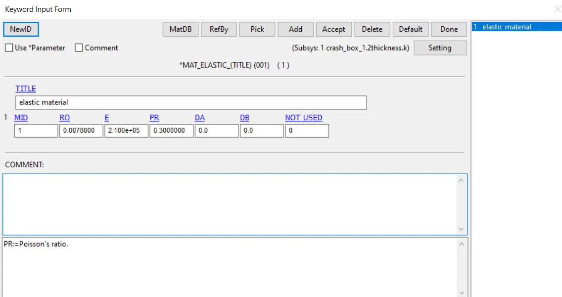
MAT-001-ELASTIC MATERIAL is defined just giving the steels density value, young’s modulus, poisson’s ratio value.
- SECTION :
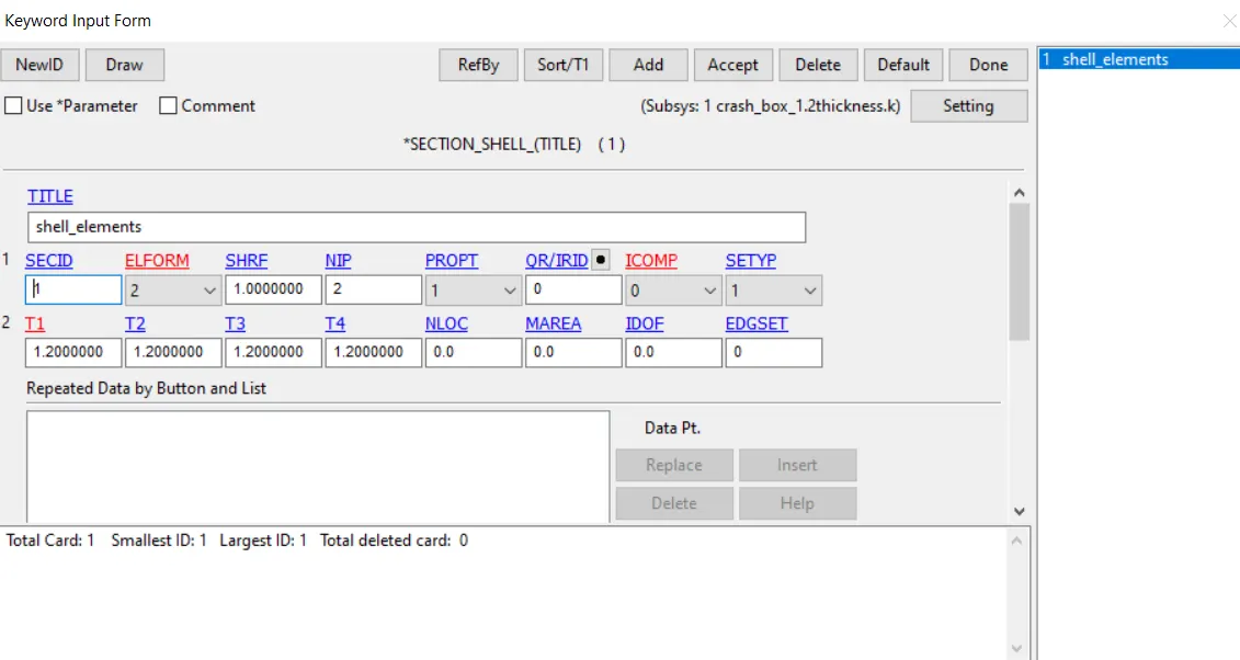
Giving the element formulation and thickness of 1.2mm and in other model 1.5mm and defining the section
- PART :
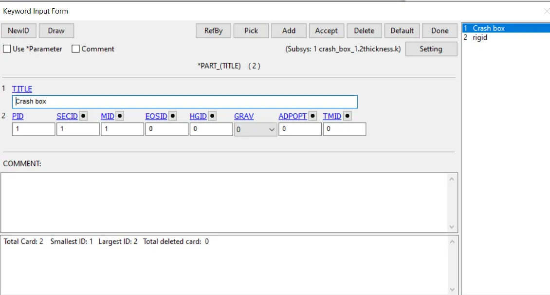
Assigning the section and material to the part
- CONTROL :
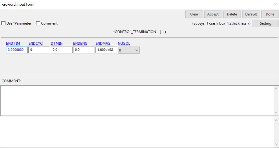
Giving the end time value
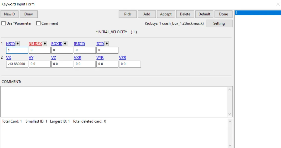
- INITIAL VELOCITY :
Giving the velocity along x axis as -13.88 mm/ms
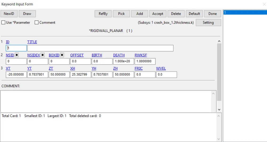
- RIGIDWALL PLANNER :
Creating the rigid planner
- DATABASE – CROSS SECTION SET :
Creating the node set and shell set of the middle part to get the force and acceleration values in the middle of cross section of the box.
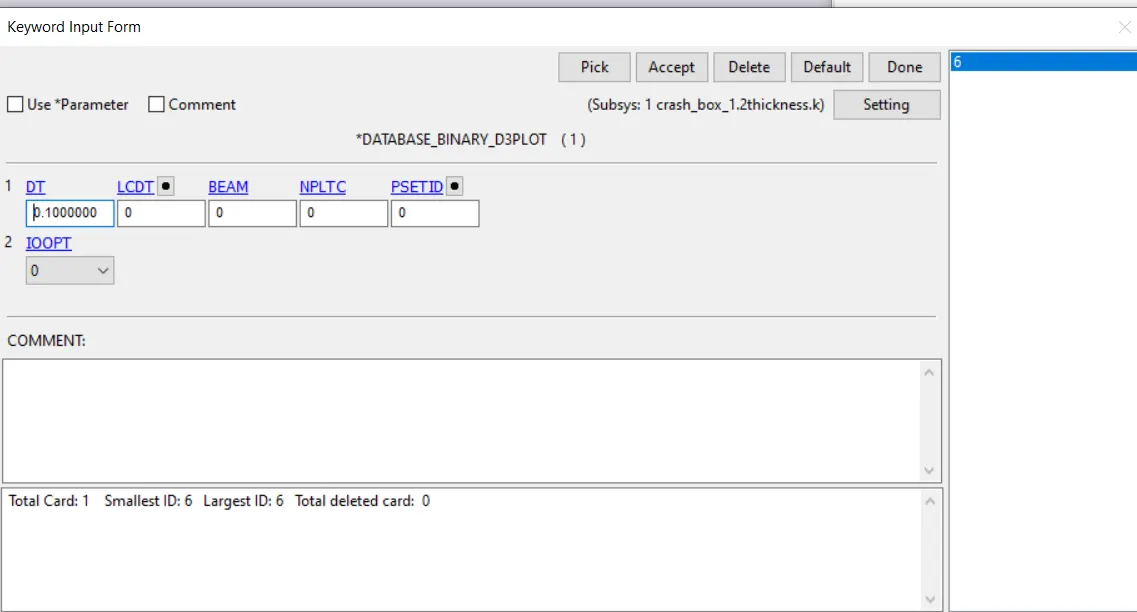
After creating the cross section set, binary d3plot as been chosen to give the time steps and ascii option is used to get the output of SECFORC(Cross section forces data),SLEOUT(Sliding interface energies),GLSTAT (Global stastics), Nodal displacement/velocity/acceleration data), RCFORC(resultant interface force), is chosen to get the output of required with giving the time interval between outputs.
Results :
Resultant force :

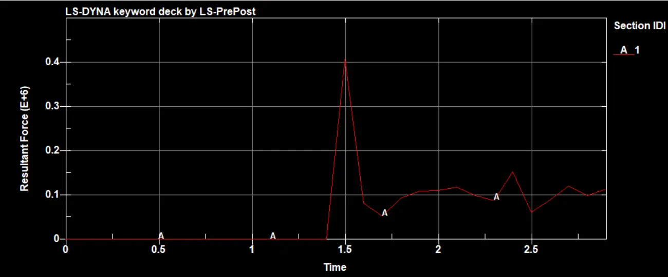
The resultant force is constant before impacting and at 1.5ms the force rise to 0.3e6 N for 1.2mm model and 0.42e6 N for 1.5mm the model rebounds back after impacting on the rigid wall.
Energy :
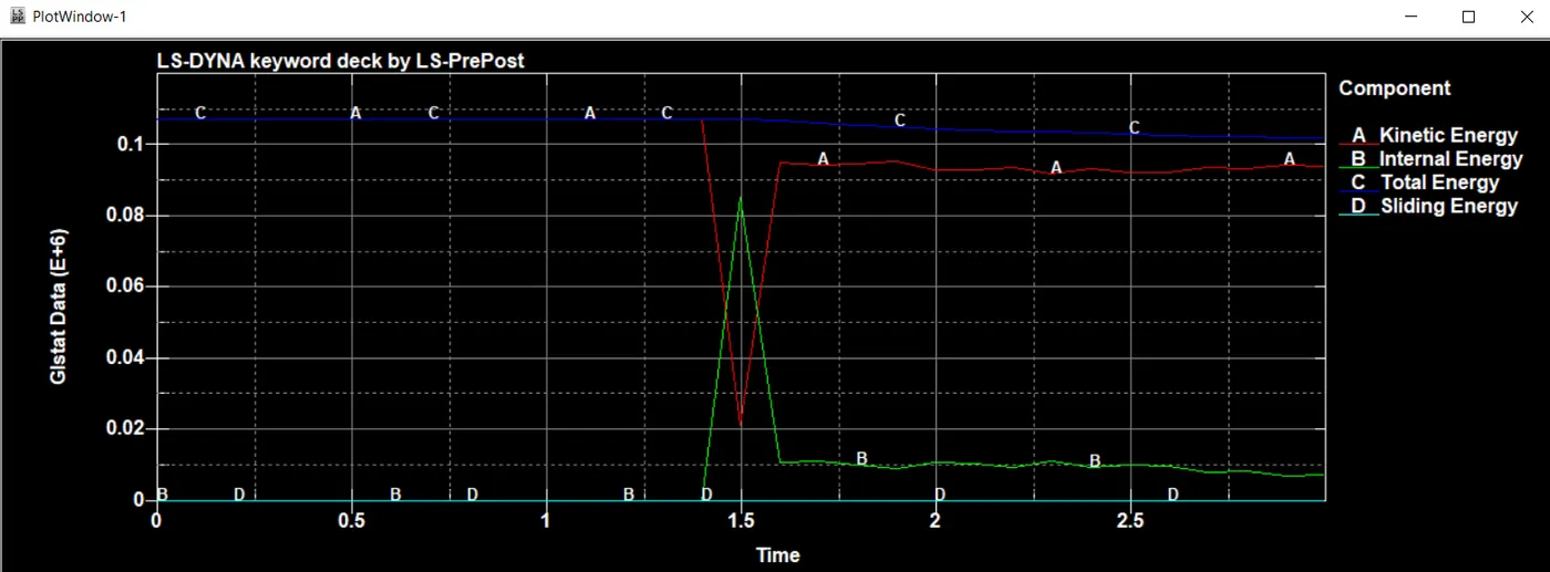
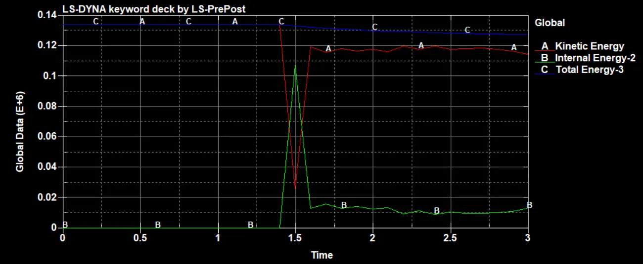
the total energy of the model is 107425 N-mm for 1.2mm and 134279 N-mm for 1.5mm and kinetic energy of the model decreases to 21326.4 N-mm for 1.2mm and 25964.4 N-mm for 1.5mm at the time of impact i.e, at 1.5ms and internal energy of the model increses to 85393.7 N-mm for 1.2mm and 107409 N-mm for 1.5mm at 1.5ms
Resultant Acceleration :
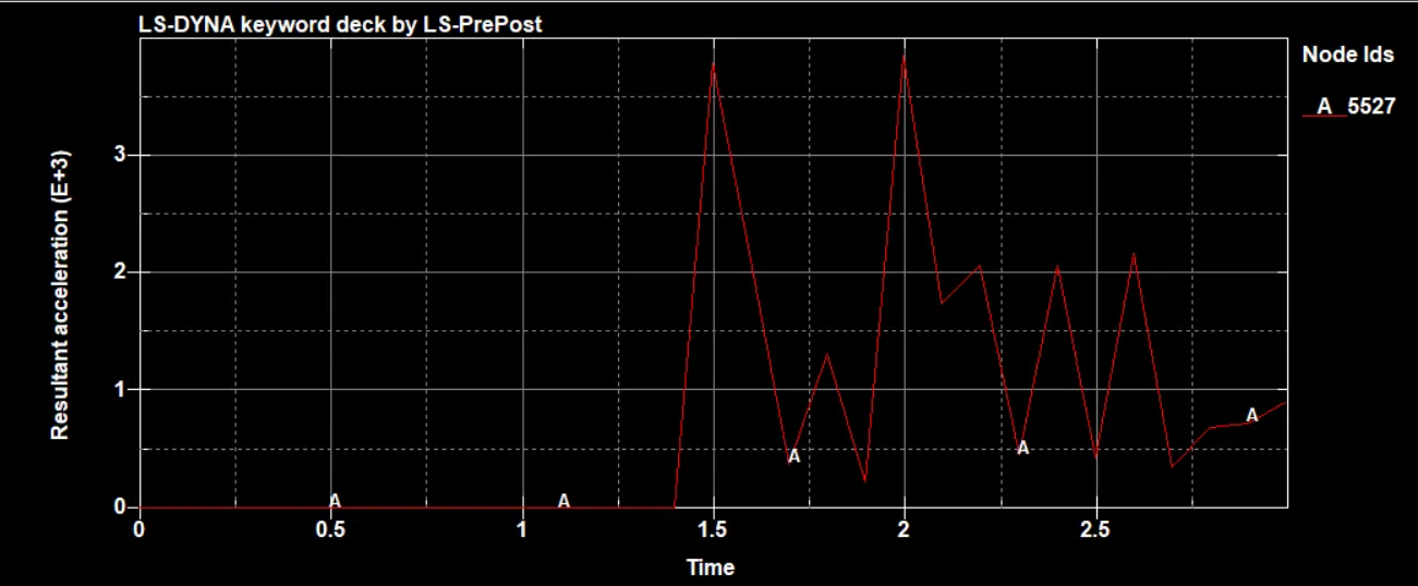
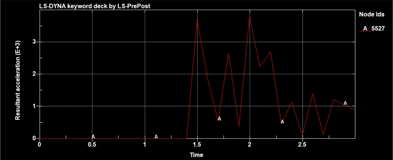
the acceleartion plot shows that accelearation at the point of impact increases to 3800 mm/ms2 for 1.2mm and 3710 mm/ms2 for 1.5mm and it goes back in the opposite direction after impact.
Resultant velocity :
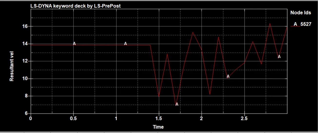
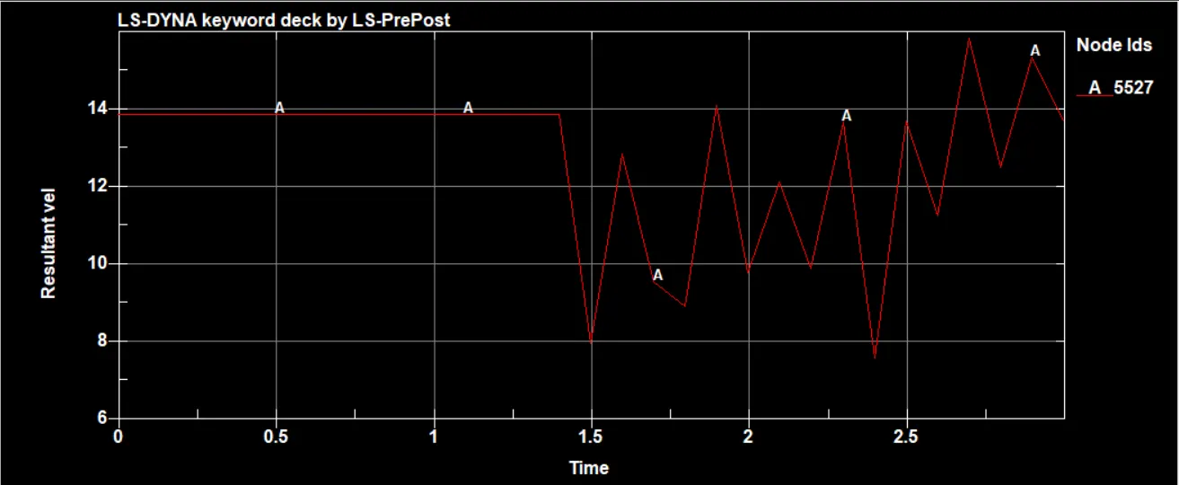
The velocity plot shows that velocity is constant before impact i.e, going at a velocity of 13.88 mm/ms and after the impact velocity decreses and the model rebound back. figure shows the plot for 1.2mm and 1.5mm respectively
maximum directional stress and strain for 1.2mm :
Max von misses stress : 744.824 N/mm2
Max X stress : 224.711 N/mm2
Max Y stress : 374.152 N/mm2
Max Z stress : 410.661 N/mm2
Max x strain : 4.475e-6
Max y strain : 1.432e-6
Max z strain : 1.351e-6
maximum directional stres and strain for 1.5mm :
Max von misses stress : 725.03 N/mm2
Max X stress : 231.701 N/mm2
Max Y stress : 367.842 N/mm2
Max Z stress: 422.594 N/mm2
Max X strain: 4.11e-6
Max Y strain: 1.38e-5
Max Z strain: 1.44e-5
The above figure shows the von misses stress varying w.r.t time.
Conclusion :
As per the given conditons the solver deck is prepared and the results are plotted.