Week - 4 - Crash Box Simulation
Aim: To do a complete simulation for crash analysis of box having two different thickness of 1.2 mm and 1.5 mm from the given FE model of crashbox.
Objectives-
- Input. k file and output files (D3PLOT, GLSTAT, SLEOUT, RCFORC)
- Animation of the final simulation
- Cross-sectional force generated in the middle of the crash box (along its length)
- Acceleration plot of a node in the middle of the crash box (along its length)
- Maximum directional stress and strain along the length of the crash box (X strain, Y strain etc.)
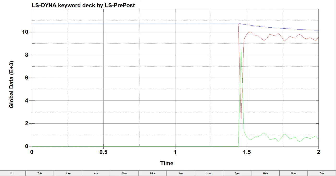
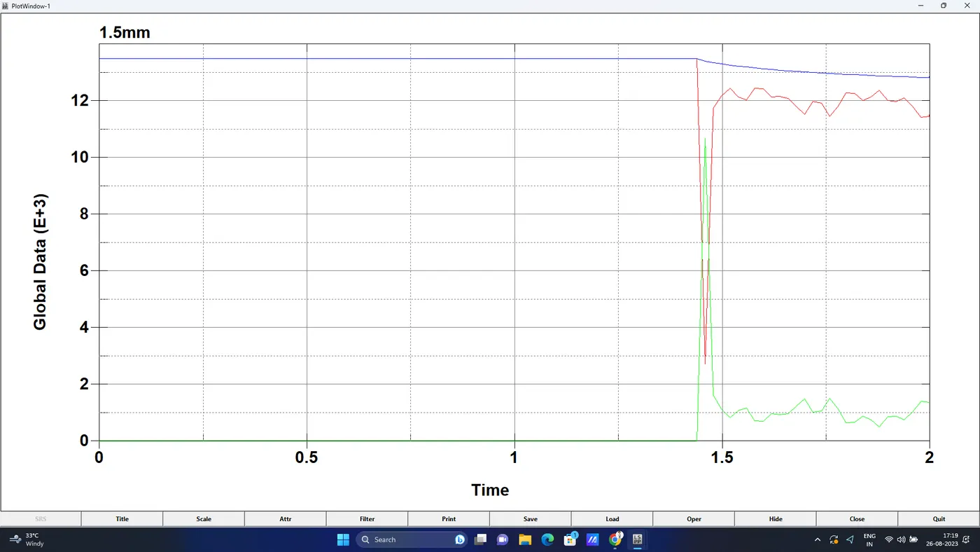
- Plot of all energies (total, internal, kinetic, hourglass, sliding)
- Compare the accelerations and stress/strain plots of 1.2/1.5mm crash boxes.
Procedure-
- We have to open the given LS-Dyna keyword (.k file) file in LS-PrePost, using option File>Open>LS-Dyna Keyword File as shown in below snap.
- Now as we can see from above snap that the model has no input so we have to give the inputs now.
- First we will start with section card, to create section card from keyword>>all>>section>>shell>>here we will input id, elform type and thickness as shown below,
- now we have to create the material card, for creating go to keyword>>all>>mat>>024 linear plasticity and now will input all material properties.
- Hourglass can be defined using HGID. This keyword is used to reduce or control hourglass energy during the simulation.
- Go to Keyword Manager and select the values as shown below.
- Now we have to assign above created properties to part id.
- Now we have to create the contact for the for the box, AUTOMATIC_SINGLE_SURFACE contact with coefficient of friction 0.2as shown below.
- Now we will create the boundary conditions for crash box for intial velocity as 50kmph which is equal to 13.89mm/ms.
- Rigid walls mimic surfaces or volumes that are frequently used to represent stiffer structures that are either stationary or in motion.
- A stationary planar rigid wall is created ahead of the frontal portion of the crash box by selecting a node on the edge, Select planar option and Geo-Vector >> 1n+NL
- Now translate the rigid wall to some distance in the direction of the velocity of crash box.
- The rigid wall is created at a distance of 20mm away from the crash box.
- Now we will define CONTROL_ENERGY card for energy dissipation as shown below.
- Finally we will define the termination time of the simulation which is necessary to run the simulation. The termination time is given as 3 ms in CONTROL SIMULATION Keyword as shown below.
- Now we have to create section for getting section for getting cross sectional forces.
- Cross-section can be created under DATA BASE keyword to measure all cross sectional forces.
- Usually, two rows of elements are selected as a section or a simple plane creation can also be done.
- Now the requested outputs are d3plot, history node and ASCII options are
- GLSTAT: Global Data
- SLEOUT: Sliding Interface Energies
- RCFORC: Resultant Interface Forces
- SECFORC: Cross Section Forces data
- Now we have to check the model from model checker.
- Since there are no errors, we can run the simulation.
- Now we will save the keyword file now and run the simulation using LS-run.
- results & Plots-
Stresses-Effective Stress (V-M), X-stress, Y-stress
1. 1.2mm thickness-
2. 1.5mm thickness-
https://drive.google.com/drive/folders/1rWGaGvNL1zL0jdS3KkxZo7tEVUoIFoKC?usp=sharing
Resultant Sectional force-
1. 1.2mm thickness-
2. 1.5mm thickness-
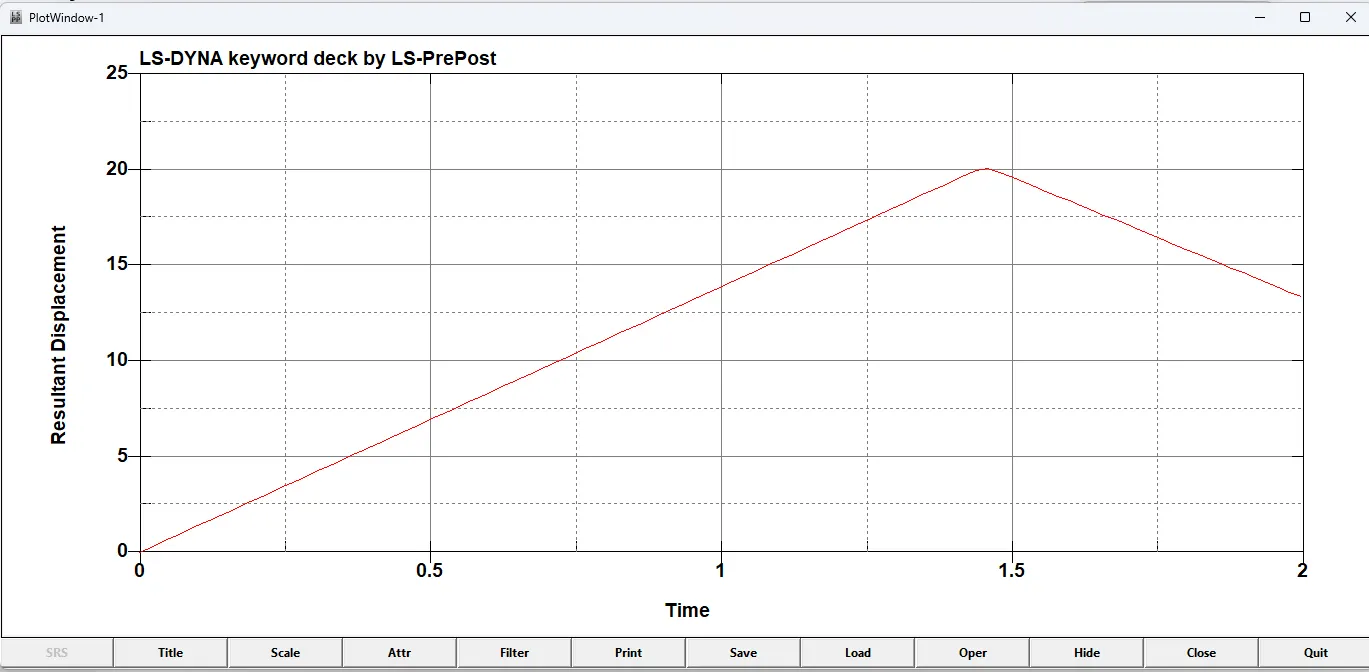
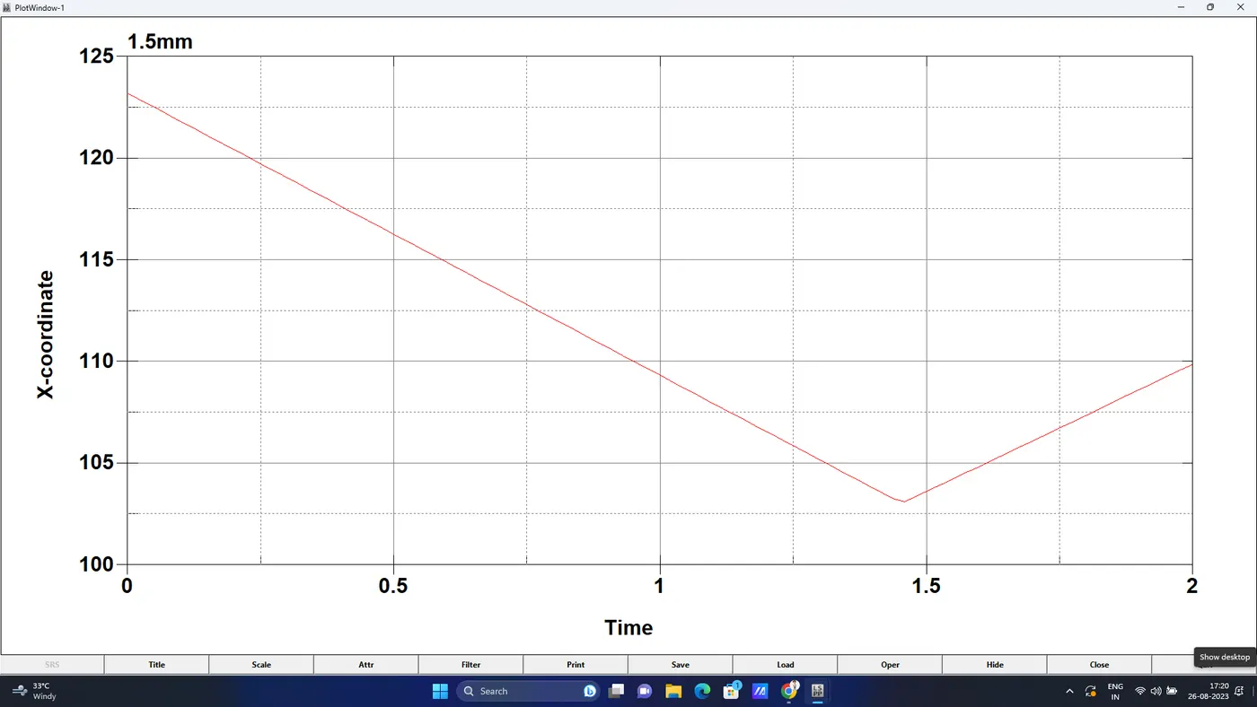
Acceleration plot of a node in the middle of the crashbox (along its length)-
1. 1.2mm Thickness-
2. 1.5mm Thickness-
Plot of all energies (total, internal, kinetic, hourglass, sliding)
1. 1.2mm Thickness-
2. 1.5mm Thickness-
Conclusion:
- The solver deck was set-up for the crash simulation and the required results were requested using the appropriate *DATABASE keyword cards.
- The analysis ran successfully. Post-processing of the results was done using the D3plots and the other output ASCII result files, to produce the deliverables.
- The keywords necessary to build the crash box analysis was created from scratch.
- The model was solved successfully and the results are compared for both 1.2 mm and 1.5 mm thick crash box.
- The results of 1.5 mm crash box showed higher energy absorbing capacity and less deformation compared to 1.2 mm thick crash
- Learned to build a solver deck for simple crash analysis in LS-Dyna and extract the outputs to interpret and compare the results.