Week - 4 - 2D meshing for Plastic components
WEEK-4 PROJECT
MID SURFACE GENERATION AND MESHING OF PLASTIC COMPONENTS WITH VARYING THICKNESS (BOTTLE CAP)
AIM:
- Import the CAD geometry of cap model
- Clean up the geometry until no topological error is found
- Extract Mid-Surface for the geometry for below quality criteria
- Mesh geometry with target/average length of 1mm
|
S.NO |
QUALITY CRITERIA |
VALUE |
|
1 |
target/average length |
1 |
|
2 |
Minimum length |
0.4 |
|
3 |
Maximum length |
3 |
|
4 |
Aspect |
3 |
|
5 |
Warpage |
15 |
|
6 |
Jacobian |
0.7 |
|
7 |
Minimum Quad Angle |
45 |
|
8 |
Maximum Quad Angle |
135 |
|
9 |
Minimum Tria Angle |
30 |
|
10 |
Maximum Tria Angle |
120 |
|
11 |
Triangles Percentage |
15 |
METHODOLOGY:
- Import the CAD Geometry and do Geometry clean-up with no topological error.
- Assign the property ID (PID) and assign different PID for each surface
- Generate mid surface
- Setup Quality criteria
- Meshing and improvement of the mesh
PROCEDURE:
- Geometry Clean-up
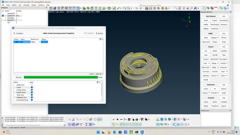
- After importing the geometry into ANSA there will be many topological errors. In order to prevent this, we do a geometry clean-up which is in the check’s manager.
- The errors in the above figure can be fixed automatically using FIX option or if the errors are not rectified, we must clear them manually.
- After all the error are rectified,if you check the geometry the exceution will be 100% then you can move forward.
2.ASSIGN PROPERTY ID (PID)
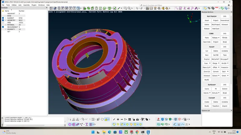
- Every part in the geometry has it’s own property. We can assign PID using ANSA. We have to select the part and click Apply, then we have to select the whole part using window selection to apply the PID. One can aslo assign different thicknesses for different parts in the PID manager.
3.GENERATE MID SURFACE
- We have to know why we are generating the mid surface. If you take any geometry, half of the thickness will be above the mid surface and other half will be below. So in order to represent the geometry we have to create mid surface. There are two ways to extract mid surface: 1)Using off-set 2)Using mid surface option.
1)Using off-set we can either create mid surface individually for each part or we can select the whole geometry using ‘Feature Selection’.Then give half the thickness for each surface selected.
2) Auto mid surface generation
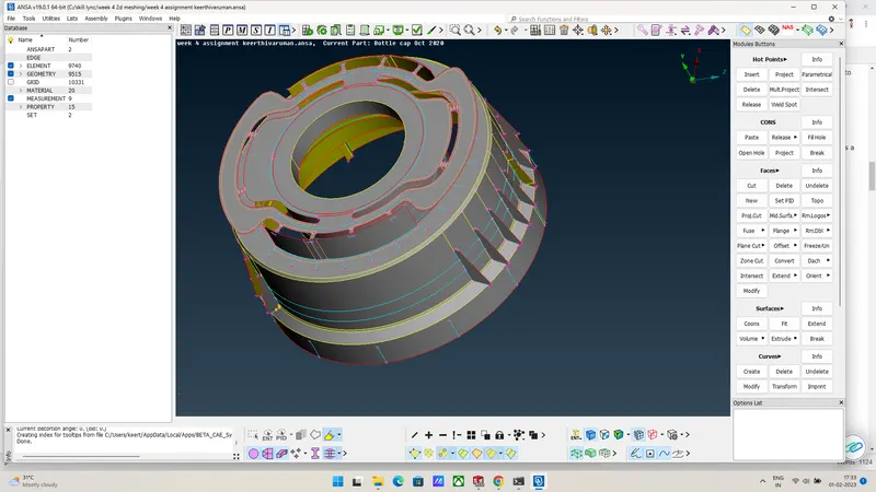
- If the geometry is a closed one we can use this option. But it will delete the parent geometry after mid surface generation. This option is available under the midsurface tab. We have to select the whole geometry and confirm the mid location. A red line indicates the generation of mid surface which is shown in the figure below.We can also use multi mid where one surface is selected with red one with green and the thickness with blue.
- Using all these options create mid surface for all the features and connect them. If there is any connectivity missing with some surfaces we can join them by creating new surfaces.In this cap model there are lot of features connected with same surfaces, as a result more triple cons can be formed.
4.QUALITY CRITERIA
|
S.NO |
QUALITY CRITERIA |
VALUE |
|
1 |
target/average length |
1 |
|
2 |
Minimum length |
0.4 |
|
3 |
Maximum length |
3 |
|
4 |
Aspect |
3 |
|
5 |
Warpage |
15 |
|
6 |
Jacobian |
0.7 |
|
7 |
Minimum Quad Angle |
45 |
|
8 |
Maximum Quad Angle |
135 |
|
9 |
Minimum Tria Angle |
30 |
|
10 |
Maximum Tria Angle |
120 |
|
11 |
Triangles Percentage |
15 |
5.MESHING AND IMPORVEMENT OF THE MESH
- Now after asigining all the quality criterias and mesh parameters we can start 2D shell meshing. The type of elemets allowed in 2D meshing are of 4 categories.
1)Quad elements 2)Tria elements 3)Parabolic quad 4)Prabolic tria.
- The quad elements are usually better than triangular elements.
- For better merge transition we use tria elements at some places. It also provides good mesh flow.
- Trias at the edges and construction lines should be avoided for better mesh flow.
- We can recreate better mesh using reconstruction option which is in the shell mesh
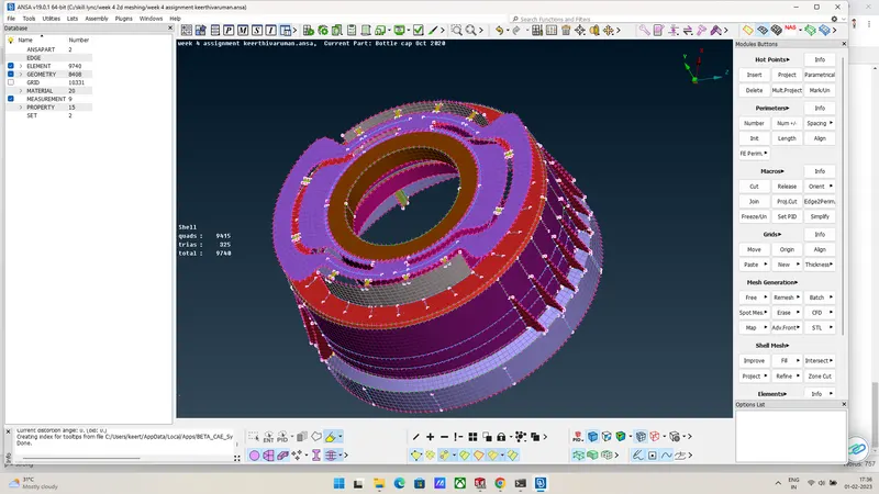
- Options used for removing Trias
- Swap, Split and Paste options are used to remove trias originated on the geometry.
- Split is available in the mesh mode under elements tab. This option is used to split the trias into quad elements easily.
- Paste is available in the mesh mode under grids tab. It is used to paste the nodes manually/automatically.
LEARNING OUTCOMES:
1. Learnt to make use of the middle tool - a third alternative to midsurface creation.
2. Also learnt the transform > rotate option, to form copies of the same surface around an axis.
3. Was able to familiarize with the intersect, extend and project tools which were required for this component.
4. Also learnt to make use of curves to generate surfaces, be it through manually created curves as well as curves generated with the help of cons.
RESULT:
The given bottle cap component was meshed as per required quality criteria, after having carried out topology cleanup and generated midsurfaces for each of its surfaces and thickness was assigned to each of them