Week - 4 - Crash Box Simulation
CRASH BOX SIMULATION USING LS-DYNA
WEEK - 4
AIM: To simulate a crash test simulation of crash box impacting a rigid wall in LS-Dyna.
OBJECTIVES:
- To create a rigid wall in LS-Dyna
- Apply initial velocity of 50 kmph to the crash box.
- Run the simulation and compare results of crash box having thickness 1.2 mm and 1.5 mm respectively.
- The unit system followed is gm-mm-ms
- Plot the cross-sectional force generated in the middle of the crash box.
1. Import:
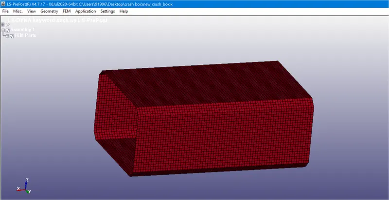
Imported Model
2. Modelling rigid wall:
- Rigid walls mimic surfaces or volumes that are frequently used to represent stiffer structures that are either stationary or in motion.
- A stationary planar rigid wall is created ahead of the frontal portion of the crash box by selecting a node on the edge, Select planar option and Geo-Vector >> 1n+NL
- Now translate the rigid wall to some distance in the direction of the velocity of crash box.
- The crash box is made to hit the stiffer rigid wall at an impact velocity of 13.88 mm/ms.
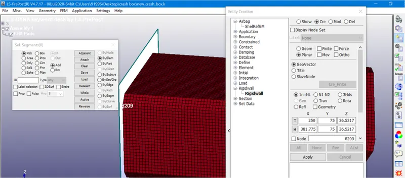
Rigid Wall Created
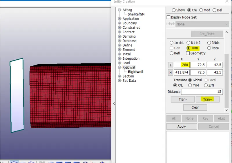
Rigid Wall Translated
3. Initial Velocity:
- Before creating the initial velocity keyword, we must create node set (NSID) for all the shell elements of the crash box.
- Go to Create Entity >> Under Set Data >> create a new SET_NODEby selecting all the elements of the box.
- Now assign that NSID in the initial velocity as shown below
- 50 kmph = 13.89 mm/ms
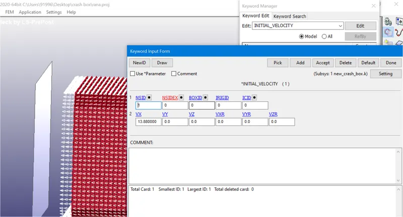
Initial Velocity Assigned To Elements
4. Shell Card selection:
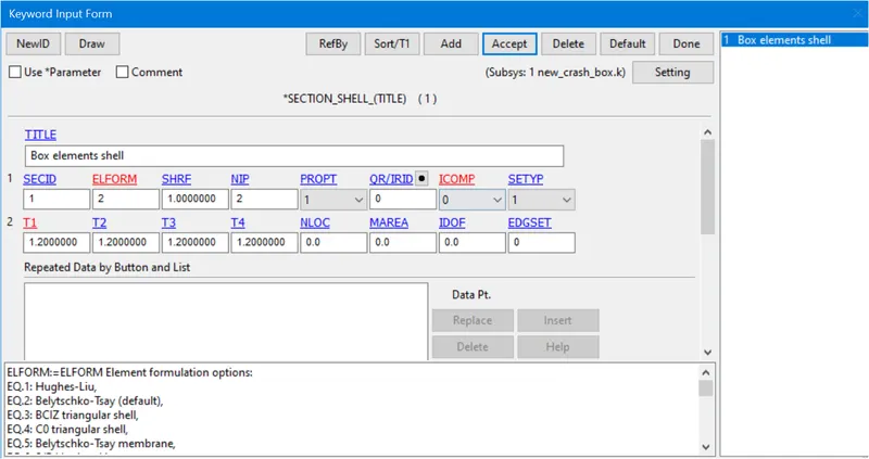
- Shell section card is required to define section properties for shell elements.
- Go to Keyword Manager
- Select section >> shell >> section ID and title.
- Choose Element Formulation value in ELFORM as 2 (Belytschko-Tsay type elements).
- Mention the thickness of the shell elements as 1.2 mm for one simulation and then 1.5 mm for the other simulation.
5. Material Card:
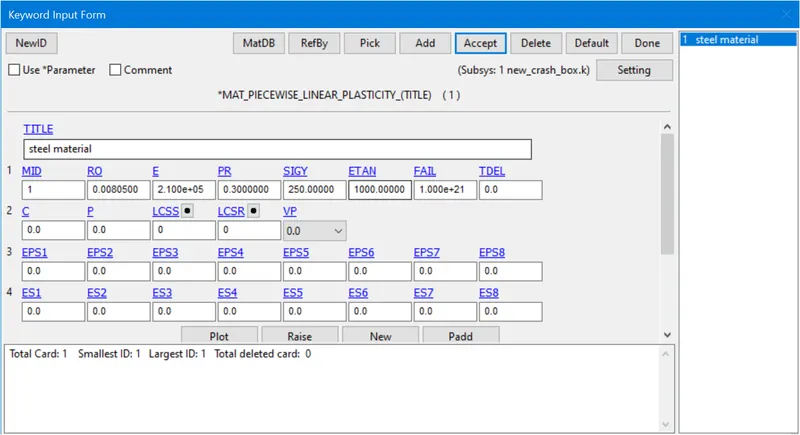
- For crash box, we will assign the material as steel which is a non-linear characteristic material.
- Go to Keyword Manager
- Select MAT >> 024-PIECEWISE_LINEAR_PLASTICITY material card. Give it a material ID and title.
- As we are using gm-mm-ms unit system, we will provide the characteristic values of steel as follows:
- Density of Steel (RO) – 8.05 x 10⁻³ gm/mm3
- Young’s Modulus (E) – 210 x 103 MPa
- Poisson’s Ratio (PR) – 0.3
- Yield Stress (SIGY) – 250 MPa
- Tangent Modulus (ETAN) – 1000 MPa
6. Hourglass:
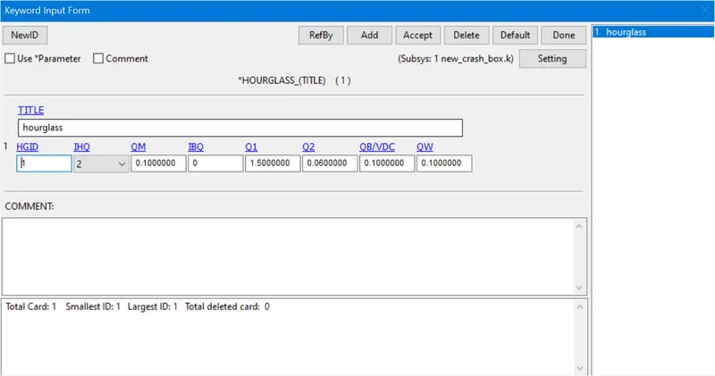
- Hourglass can be defined using HGID. This keyword is used to reduce or control hourglass energy during the simulation.
- Go to Keyword Manager and select the values as shown below.
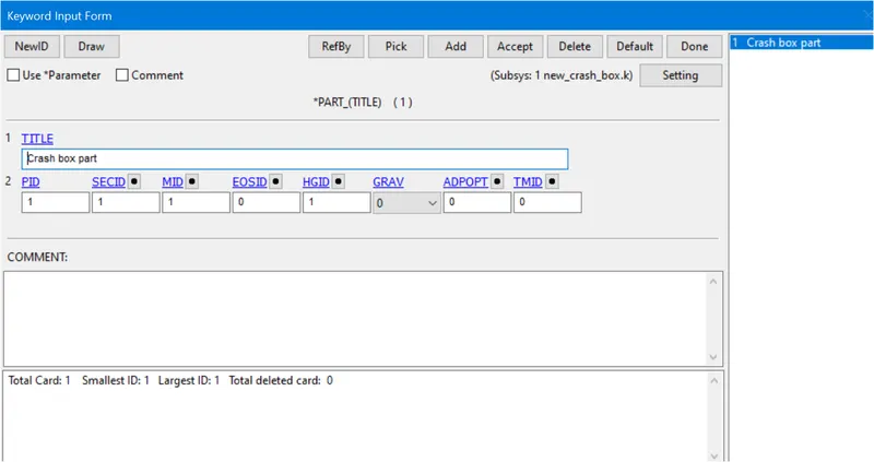
- Now assign all these characteristics to the crash box part in PART keyword as shown below.
7. Contact:
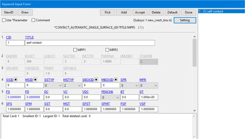
- Contact card can be used to define self-contact for crash box as the crash box elements can have contact between themselves after the deformation. Therefore, define AUTOMATIC_SINGLE_SURFACE contact with coefficient of friction 0.2as shown below.
8. Control:
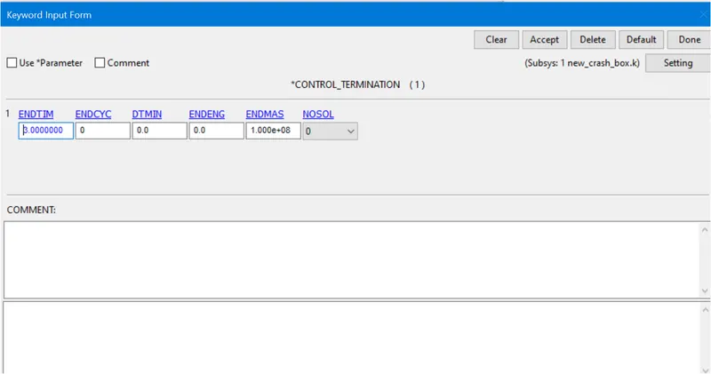
- Define the termination time of the simulation which is necessary to run the simulation. The termination time is given as 3 msin CONTROL SIMULATION Keyword as shown below.
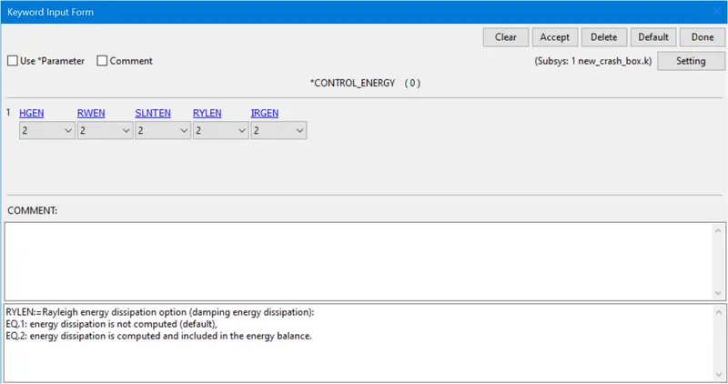
- Now define CONTROL_ENERGYcard for energy dissipation as shown below
9. Cross-section:
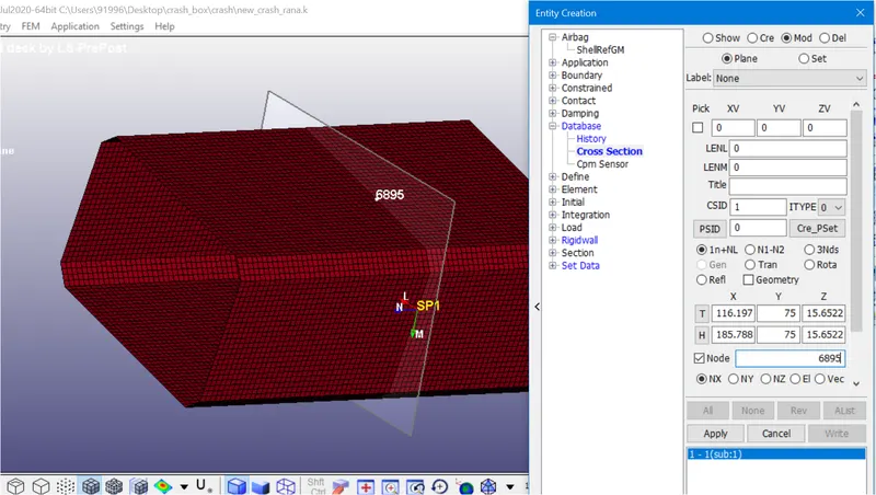
- Cross-section can be created under DATA BASE keyword to measure all cross sectional forces.
- Usually, two rows of elements are selected as a section or a simple plane creation can also be done.
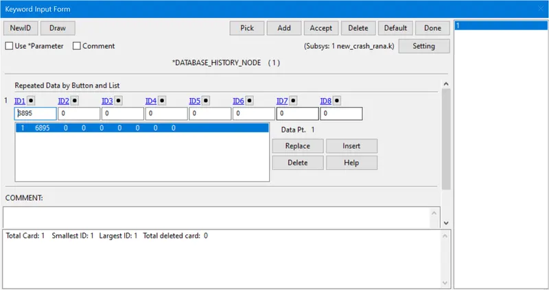
- History node can be used to know the acceleration at the node during the simulation
10. Post-Processing Results:
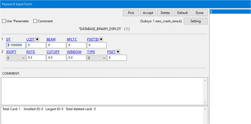
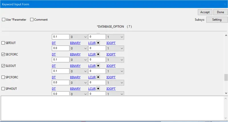
- The requested outputs are d3plot, history node and ASCII options are
- ELOUT:Element Data
- GLSTAT:Global Data
- MATSUM:Material Energies
- SLEOUT:Sliding Interface Energies
- NODOUT:Nodal point data
- SECFORC:Cross-section forces
11. Model Checker
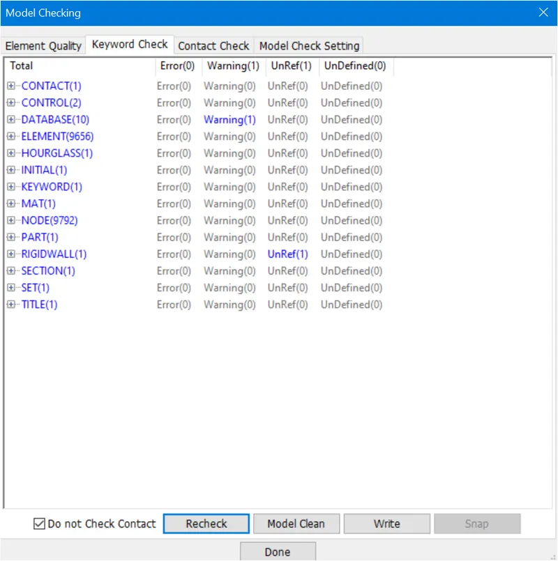
- Since there are no errors, we can run the simulation.
- After creating all the necessary files for simulation and checking the model, we will save the model as Keywordfile with .K extension. To run the model, we will go to File > Run LS-DYNA. We will browse this keyword file and then run the simulation for shell thickness 2 mm and then for shell thickness 1.5 mm as shown below.
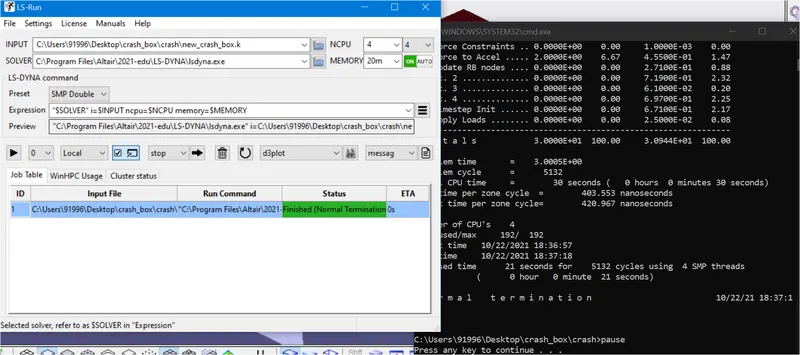
Simulation For 1.2mm thickness is done
Now the solver deck setup is complete and ready to run the Analysis. We need to run the analysis for 2 thicknesses, one 1.2mm and the other, 1.5mm. The Solver deck that we have created here is for a 1.2 mm thick model. Thus, we need to create another solver deck for the 1.5 mm thick model. This can be done very easily by simply changing the thickness value under the section definition in the Keyword file by opening it in Notepad. Then save it as a new file.
RESULTS:-
The D3plot output File is opened in LS-PrePost using option File > open > LS-Dyna binary plot.
The animation of Von-Mises stress for 1.2 mm thick crash box is as shown below.
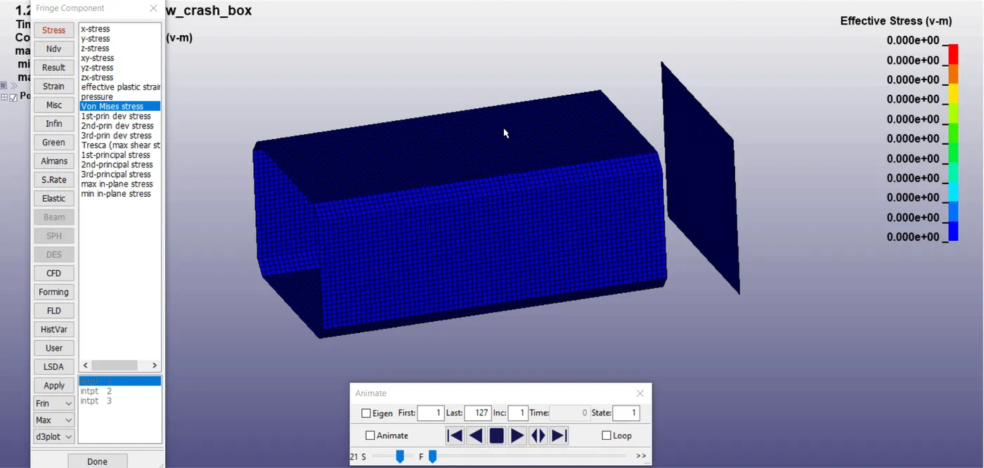
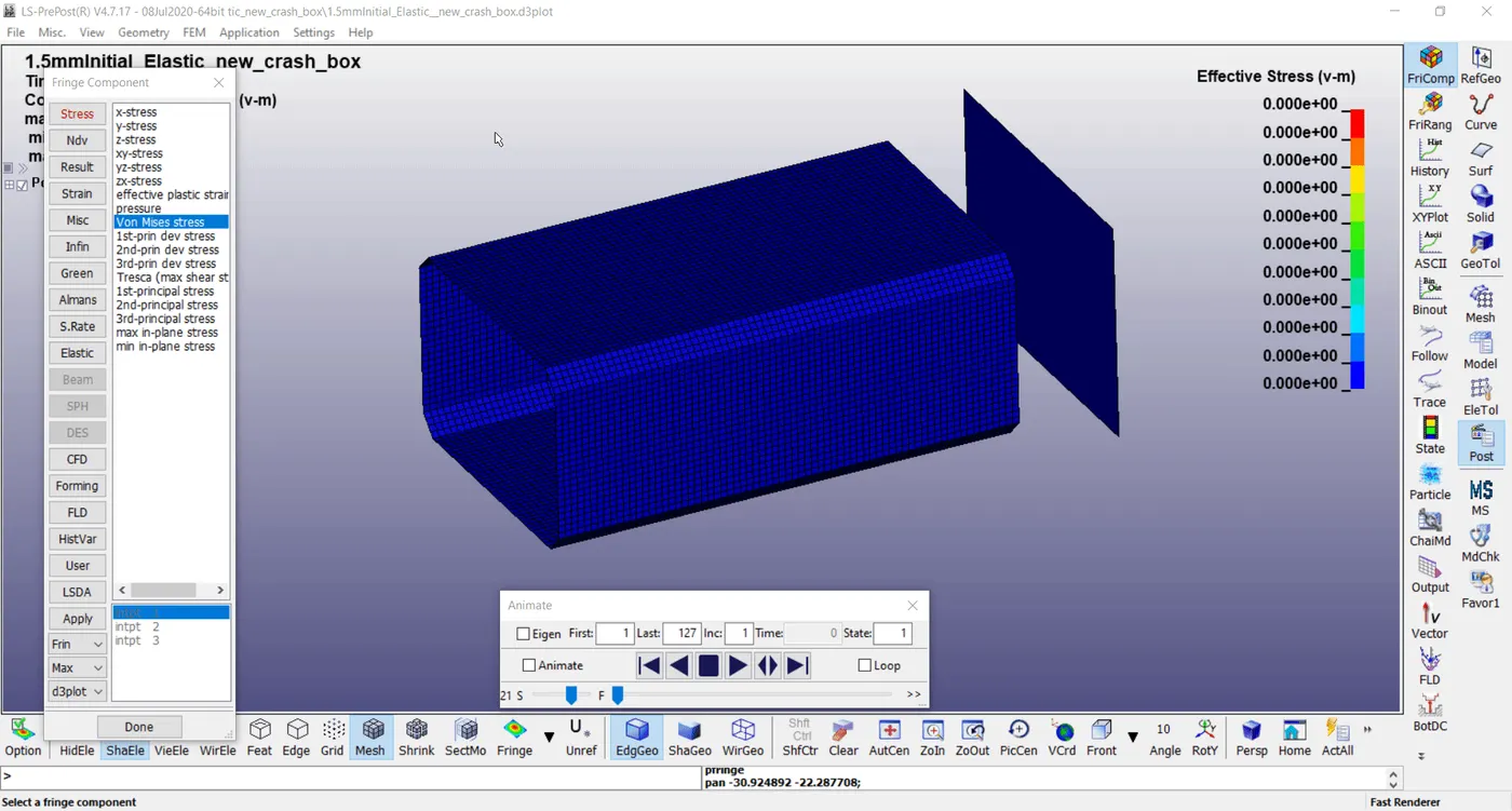
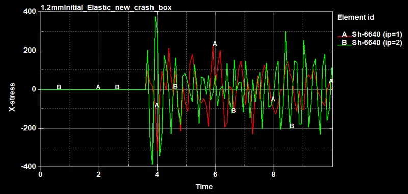
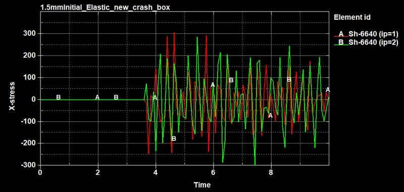
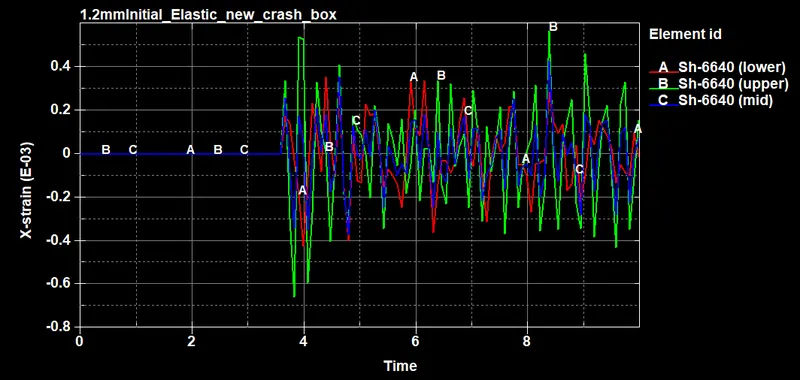
Below images shows the comparision on the basis of various energies, stress, strain, acceleration etc. between crashbox having 1.2mm and 1.5mm thickness.
Cross Sectional Force Comparision:-
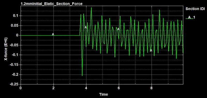
Max. Cross Sectional Force along the length of the crashbox in the X-dir is found to be 1.44e+5 (gm mm/ms^2) at 4.32ms while Min. Cross Sectional Force along the length of the crashbox in the X-dir is found to be -2.06e+5 (gm mm/ms^2) at 3.76ms.
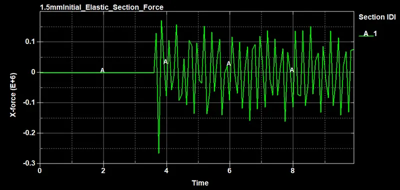
Max. Cross Sectional Force along the length of the crashbox in the X-dir is found to be 1.73e+5 (gm mm/ms^2) at 3.84ms while Min. Cross Sectional Force along the length of the crashbox in the X-dir is found to be -2.65e+5 (gm mm/ms^2) at 3.76ms.
Acceleration Comparision:-
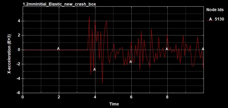
Above image displays the variation in the acceleration of a central node over the entire period of simulation. Max. Nodal Acceleration along the length of the crashbox in the X-dir is found to be 4.67e+3 (mm/ms^2) at 3.68ms while Min. Nodal Acceleration along the length of the crashbox in the X-dir is found to be -4.63e+3 (mm/ms^2) at 4.4ms.
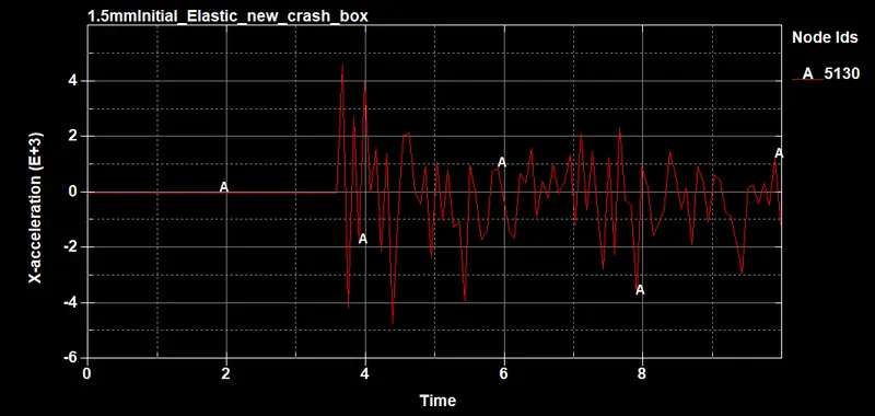
Above image displays the variation in the acceleration of a central node over the entire period of simulation. Max. Nodal Acceleration along the length of the crashbox in the X-dir is found to be 4.59e+3 (mm/ms^2) at 3.68ms while Min. Nodal Acceleration along the length of the crashbox in the X-dir is found to be -4.73e+3 (mm/ms^2) at 4.4ms.
Energies Comparision:-
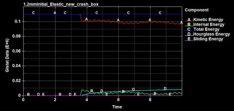
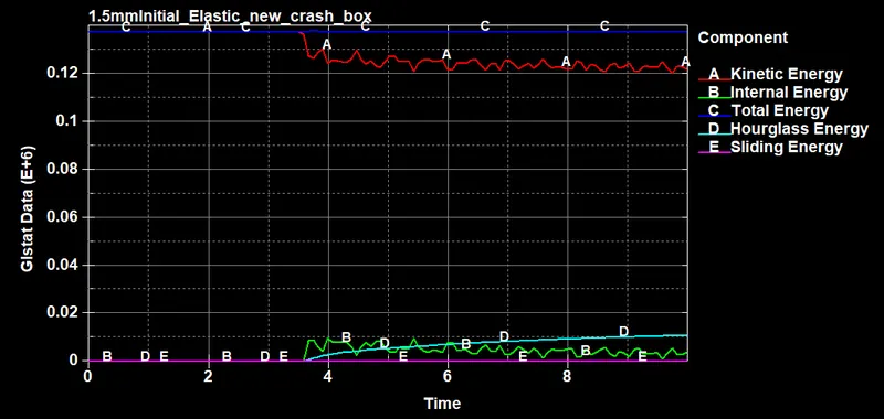
it can be seen that when the crash box hits the rigid wall, there is a reduction in the kinetic energy of the box while there is an increment of the internal energy of the wall and after that both energies become constant. This validates the principle of conservation of energy which states that energy can neither be created nor destroyed but can be converted from one form of energy to another. Moreover, from the plot it can also be seen that the hourglass energy remains very low throughout, indicating a good selection of both the hourglass and element formulation for the simulation setup. Basically Hourglass Energy upto 10% of the Internal Energy can be accepted which is achieved here.
X-Stress Comparision:-
X-Strain Comparision:-
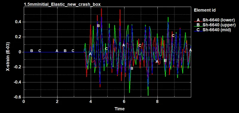
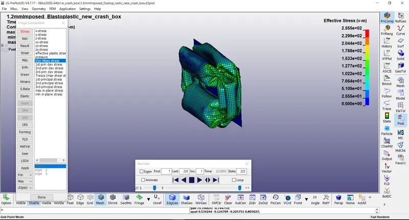
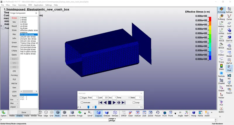
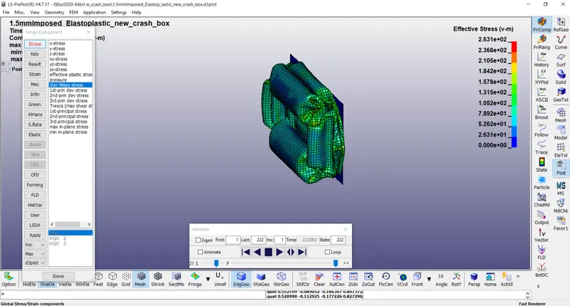
The same simulation was run for Imposed velocity with Elastic material and Imposed velocity with Plastic material using some additional keywords defined like CONTACT_SINGLE_SURFACE and BOUNDARY_PRESCRIBED_MOTION_SET.
Imposed velocity with Elastic material -
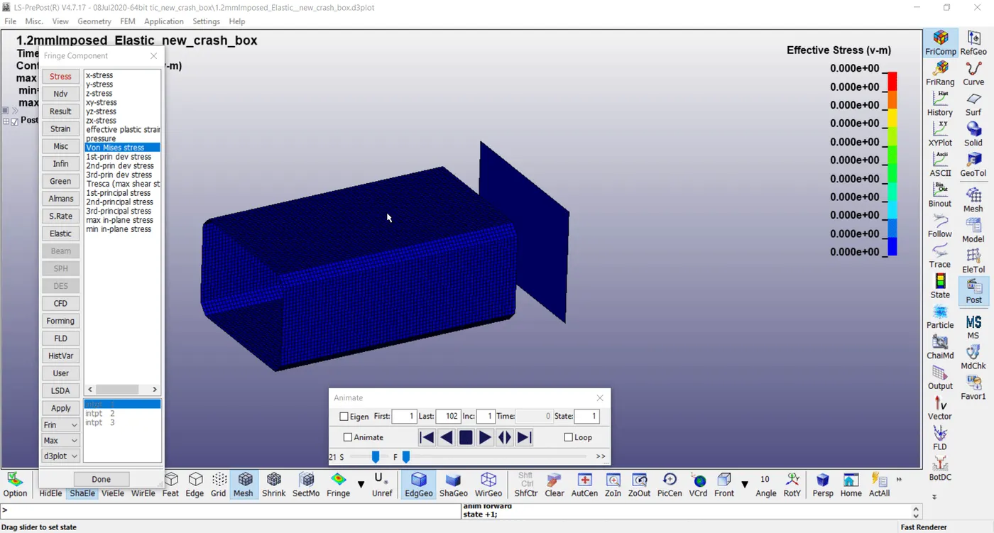
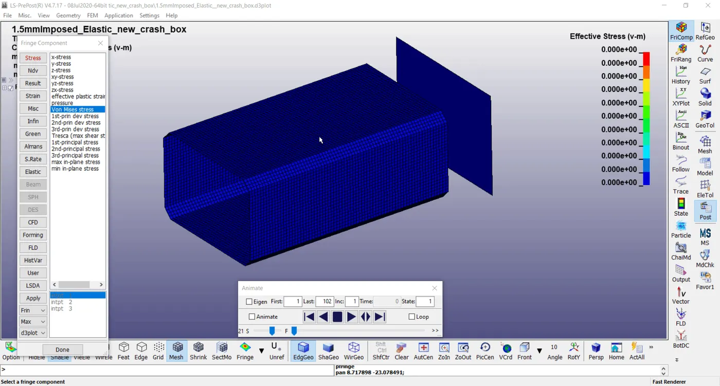
Imposed velocity with Plastic material -
For 1.2mm Thickness
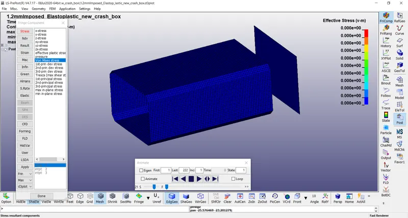
For 1.5mm Thickness
RESULT:-
The main aim of the Week 4 challenge was to create an input deck or setup file to perform the crash analysis of crash boxes with different thicknesses using LS-DYNA software and analyze the behavior of stress-strain and other results while and after the crash boxes hit the rigid wall. The crash simulations of the boxes were performed for scenario where the crash boxes hit rigid wall and rebounds back completely. From the GLSTAT plots, it was found that the simulation setup follows and validates the principle of conservation of energy expressing loss of kinetic energy of crash boxes conversely leads to the gain of internal energy of the rigid wall.