Week - 4 - Crash Box Simulation
Aim:
To simulate a crash test for the given simple crash box structure. The given crash box structure has mesh already provided. The crash box shall be simulated with following conditions:
- The crashbox to be crashed into a rigidwall created using *RIGIDWALL_ keyword
- Material for the crashbox is to be assigned as steel. The simulation to be started using elastic material to verify its correctness and later a nonlinear material card data will be provided. Thickness of the crashbox to be assigned as 1.2mm.
- Initial velocity for the crashbox should be assigned as ~50 kmph
- The units system to be used as gm-mm-ms
- The simulation should satisfy either of the two situations - (1) It crashes on the rigidwall and rebounces completely or (2) it buckles and folds in the axial direction so as to come in self-contact.
- Once the simulation is completed and results as asked below is collected, another simulation is to be run by increasing the thickness of the crashbox from 1.2 to 1.5mm
The following results are to be delivered:
- Input .k file and output files (d3plot, glstat, sleout, rcforc)
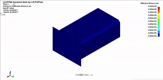
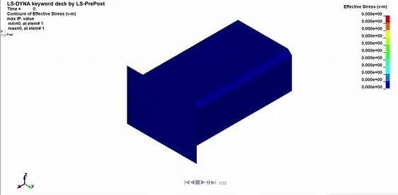
- Animation of the final simulation
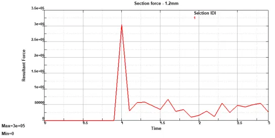
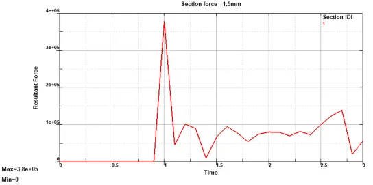
- Cross-sectional force generated in the middle of the crashbox (along its length)
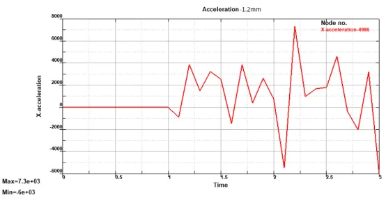
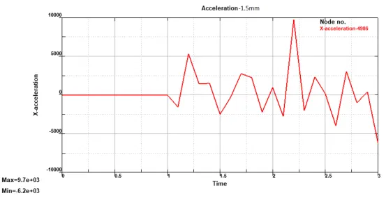
- Acceleration plot of a node in the middle of the crashbox (along its length)
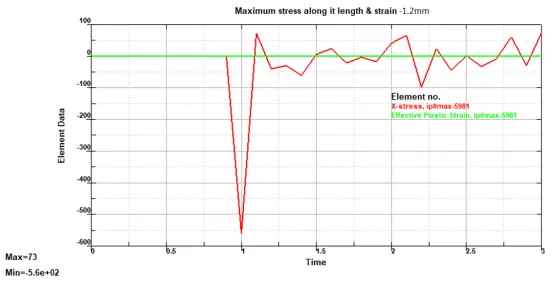
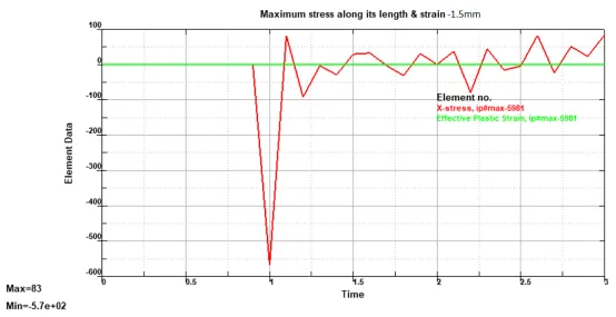
- Maximum directional stress and strain along the length of the crashbox (X strain, Y strain etc)
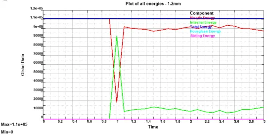
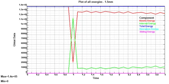
- Plot of all energies (total, internal, kinetic, hourglass, sliding)
- Compare the accelerations and stress/strain plots of 1.2/1.5mm crashboxes.
Procedure:
- Open the given model:
The given file is opened using File --> Open --> LS-Dyna Keyword file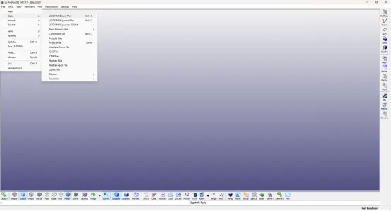
- Material card creation:
- Elastic material creation:
- Select Keyword Manager present on the right side of the tool bar
- Once the keyword manager window opens, select ALL
- Go to MAT --> Select 001-Elastic --> Keyword Input Form window opens
- In the Keyword Input form window, enter the Material name in TITLE, a unique material ID in MID and the other material properties like density, Youngs Modulus and Poission ratio. Unit of measurement followed in this project is gm-mm-ms.
- Elastic material creation:
- Rigidwall:
- Select Create Entity on the right side of the tool bar
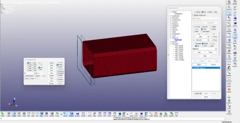
- Go to RIGIDWALL --> Create --> PLANAR --> GeoVector --> 1n+NL --> Select a Node --> Apply --> Tran --> Enter distance as 15 --> Tran+ --> Apply --> Done
- Section card creation:
- In the Keyword manager, select All --> Shell --> Keyword Input Form window opens --> Enter SECID, ELFORM, T1, T2, T3 & T4 --> Select Accept --> Done
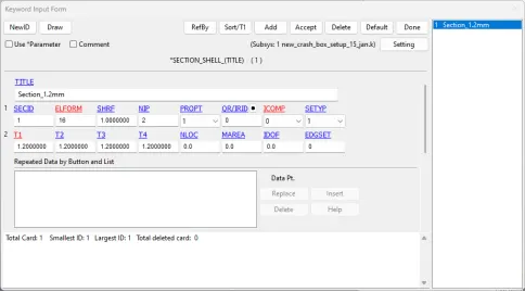
- In the Keyword manager, select All --> Shell --> Keyword Input Form window opens --> Enter SECID, ELFORM, T1, T2, T3 & T4 --> Select Accept --> Done
- Hourglass creation:
- In the Keyword manager, select All --> HOURGLASS --> HOURGLASS --> Enter Title, HGID --> Select THQ as 4 to take Hourglass control as “Flanagan-Belytschko stiffness form”. This algorithm adds stiffness to the element to compensate for the hourglass effect.
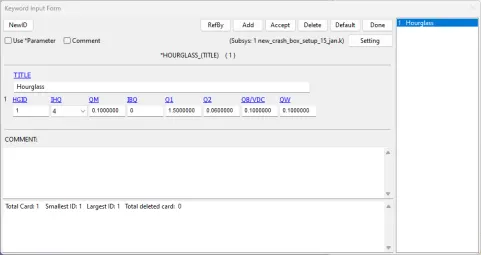
- In the Keyword manager, select All --> HOURGLASS --> HOURGLASS --> Enter Title, HGID --> Select THQ as 4 to take Hourglass control as “Flanagan-Belytschko stiffness form”. This algorithm adds stiffness to the element to compensate for the hourglass effect.
- Initial Conditions:
- In the Toolbar on the right side of the window, select Create Entity
- Select Initial --> Velocity
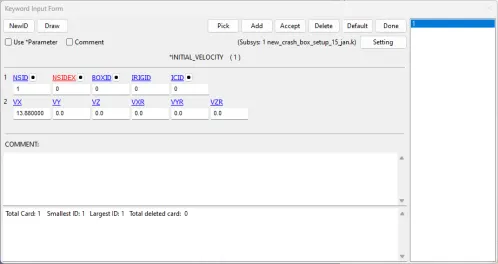
- In the Keyword Input form window, enter the velocity Vxas 88 m/s --> select Accept
- Select the dot button near NSID --> Link_SET_NODE window opens --> Select NewEntity --> Entity creation window opens
- In the Entity creation window, select Pick --> Select ByPart --> Select the crash box part --> Apply
- In the Keyword Input form window, select Accept --> Done
- Contact card creation:
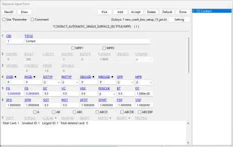
- In the Keyword manager, select All --> CONTACTS --> AUTOMATIC_SINGLE_SURFACE --> Enter CID & TITLE --> For this contact type, SSTYP & MSTYP can be ignored --> Enter friction parameters FS & FD as 0.2 --> Click Accept --> Done
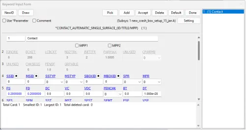
- In the Keyword manager, select All --> CONTACTS --> AUTOMATIC_SINGLE_SURFACE --> Enter CID & TITLE --> For this contact type, SSTYP & MSTYP can be ignored --> Enter friction parameters FS & FD as 0.2 --> Click Accept --> Done
- Control card creation:
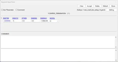
- In the Keyword manager, select All --> CONTROL --> TERMINATION --> Enter ENDTIM value --> Click Accept --> Done
-
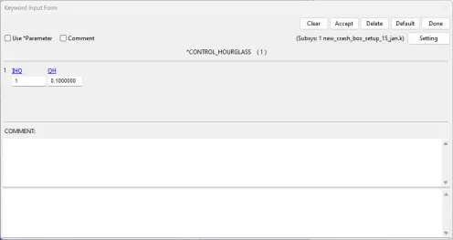
In the Keyword manager, select All --> CONTROL --> HOURGLASS --> Enter THQ as 1.0 --> Click Accept --> Done
-
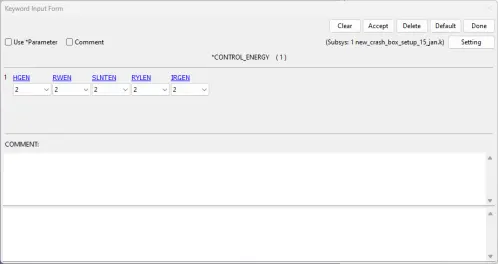
In the Keyword manager, select All --> CONTROL --> ENERGY --> Select HGEN, SLNTEN, RYLEN as 2 --> Click Accept --> Done
- In the Keyword manager, select All --> CONTROL --> TERMINATION --> Enter ENDTIM value --> Click Accept --> Done
-
Part card creation:
-
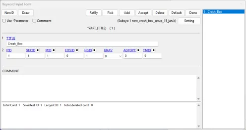
In the Keyword manager, select All --> Part --> Enter TITLE --> Enter PID --> Select the small dot button near SECID --> Select the correct section in the link section window --> Done --> Repeat the same in MID field and select the appropriate material --> Select the appropriate HGID --> Select Accept --> Select Done
-
-
Database card creation:
-
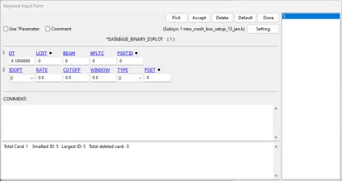
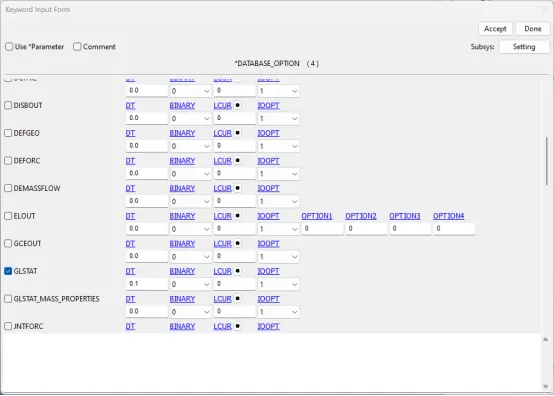
In the Keyword manager, select All --> DATABASE --> Select BINARY_D3PLOT --> Enter DT as 0.1 --> Click Accept --> Done
-
In the Keyword manager, select All --> DATABASE --> Select ASCII_option --> Check the GLSTAT, RCFORC, SECFORC, SLEOUT --> Enter DT as 0.1 --> Click Accept --> Done
-
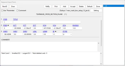
Create database for recording cross sectional forces:
- Select Create Entity on the right side of the tool bar
- Select Database --> Cross Section --> Create --> Plane --> 1n+NL --> Select Node --> Use Tran & Rota for adjusting the center of the vector to the center of the crash box section
-
- Save the file using File --> Save --> Save Keyword as a .k file
- Run the .k file using File --> Run LS Dyna --> LS Run window opens --> Select the saved .k file in the INPUT field --> Select the "Add job to local queue" to run the simulation --> A command prompt window opens --> Once the simulation is done, the processing in the command prompt stops
- View the output:
- Select File --> Open --> LS Dyna Binary Plot --> Select the d3plot file
- To view the Fringe component:
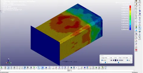
- In the right side toolbar, select Fringe Component --> Fringe Component window opens
- Select the required result to view as fringes --> Done
-
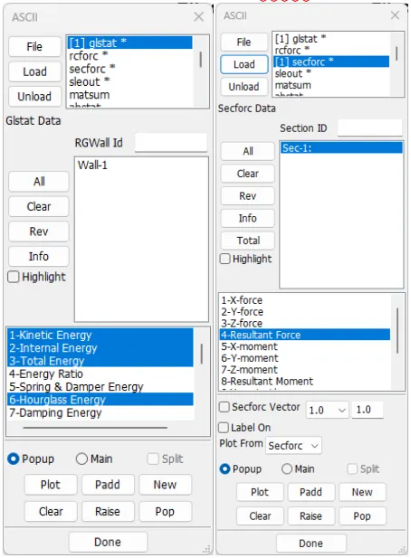
To plot the energies & sectional force, the ASCII option is used. In which, the energies can be plotted by loading the glstat file and sectional force using the secforc file
-
For plotting the maximum acceleration of a node, select Plot --> History --> Nodal --> X-acceleration --> Select node --> Plot
-
For plotting the stress and strain, select Plot --> History --> Element --> X-stress & Effective plastic strain --> Select element --> Plot
-
Results:
-
Animation:
-
Crash box with section 1.2mm:
- Crash box with section 1.5mm:
-
-
Cross-sectional forces generated:
-
Acceleration plot of a node:
-
Maximum directional stress and strain:
-
Plot of all energies:
-
-
Comparison of results:
Acceleration (mm/ms²)
Maximum stress (g/mm-ms²)
Section - 1.2mm
7.3e+03
73
Section - 1.5mm
9.7e+03
83
- The maximum strain is zero because the material used in this simulation is considered as elastic and not elastic-plastic
- The acceleration and maximum stress of both the crash box sections happen at t=1 sec
- The maximum acceleration of crashbox with the section 1.5mm is around 24.75% more than the crash box with section 1.2mm
- The maximum stress induced in crashbox with section 1.5mm is 12.04% more than the crashbox with section 1.5mm
Result:
The given crash box structure has been simulated for two section sizes and the required results are produced and compared.
Note: The keyword and the plot files are uploaded in Google Drive.