Week - 4 - Crash Box Simulation
AIM
Crash analysis of rectangular box
OBJECTIVE
- Strain and stress at the middle of box.
- Different energies flow in the system.
- Comparing the results according to the simulation.
- Crash and rebounded back
- Comparing results for different thickness.
- Thickness 1.2mm
- Thickness 1.5mm
INPUT GIVEN
- Define through keyword *RIGIDWALL.
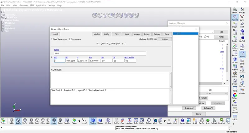
- Crash box material is steel.
- Initial velocity of the crash box is 50 km/hr.
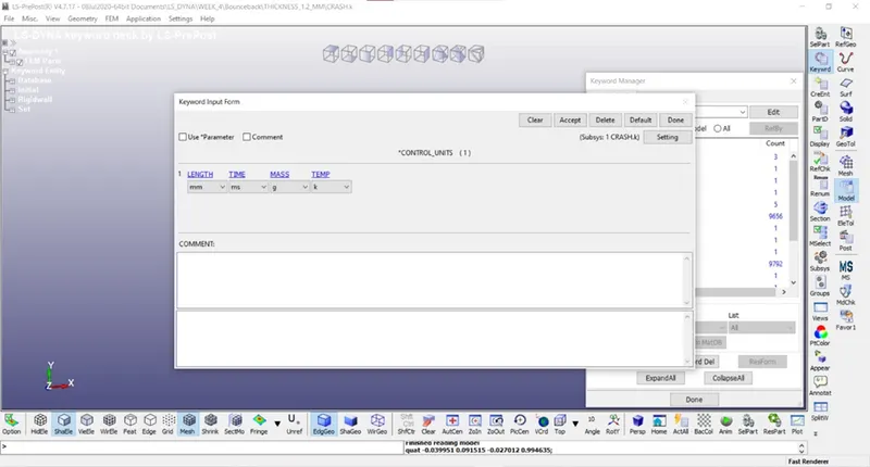
- Unit system is “GRAM MILLIMETER MILISECOND”.
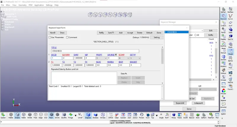
- Thicknesses are 1.2 mm & 1.5 mm.
- Types of simulation Crash and rebounded back & buckles and folds in axial direction.
OUTPUT
- Cross sectional force along its length in the middle of crash box.
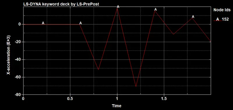
- Acceleration plot of a node in the middle of crash box.
- Maximum direction stress and strain along the length of crash box (x strain, y strain)
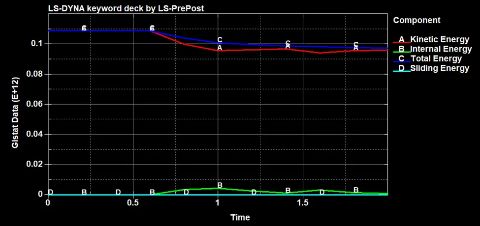
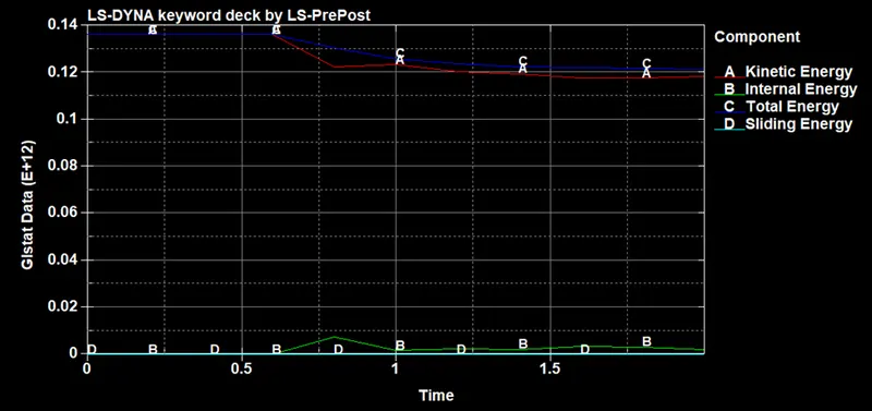
- Plot all energies (Total energy, Internal energy, Kinetic energy, Hourglass, sliding energy).
- Compare acceleration and stress/strain plots 1.2 mm/1.5 mm of crash box.
- Output in format D3PLOT, GLSTAT, SLEOUT, RCFORCE.
THEORY
Crash refers to collide violently with an obstacle. In this analysis a rectangular shell box is crashed against the rigid wall. The stress and strain at the middle of box and how the energies flow is demonstrated for different thickness of rectangular box.
PROCEDURE
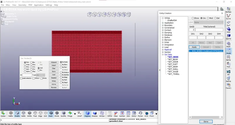
- Set nodes
In this all the rectangular shell box nodes are defined.
Model > Create Entity > Set nodes
- Units
In this desired unit is assigned.
Model > Keyword > Control > Units
- Material
In this suitable material is defined for the rectangular shell box.
Model > Keyword > Mat > Elastic material
- Section
In this section is defined with the help of nodes set.
Modal > Section > shell
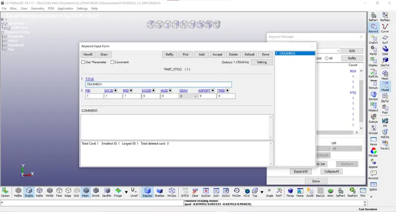
- Combine material and section
In this the material and shell is attached together.
Part >
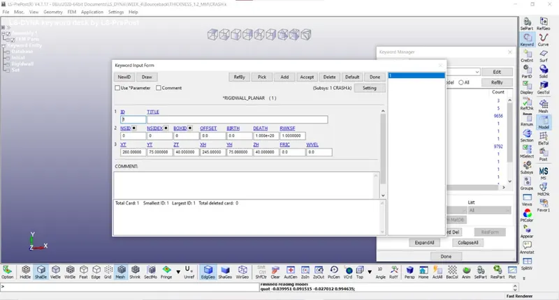
- Rigid wall
In this a rigidwall is defined as per the question.
Model > create entity > rigidwall
- Hourglass
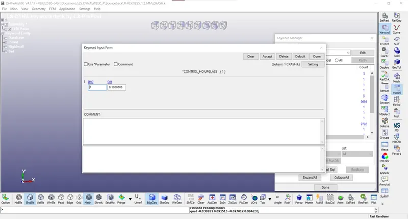
Since for collecting the data of each element is time taking process so a local coordinate system is defined through reduce integration method which inserted one nodes at each element, but since it is located at the middle of each element it get not displaced hence there is an error and this error is known as Hourglass error. So by defining hourglass the deformation experienced by the edge nodes is transferred to center node and finally error is reduced.
Model > Control > hourglass
- Termination
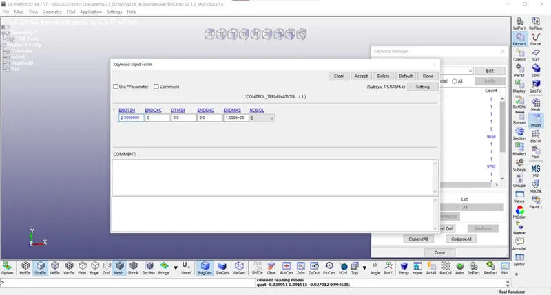
In this stop time for simulation is assigned.
Model > Control > Termination
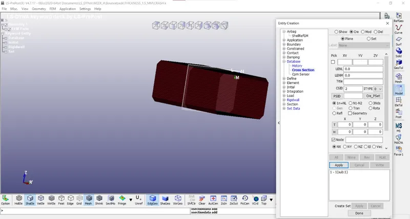
- Node and cross section
In this a node and plane is defined so the result at that point is observed.
Model > Create Entity > Cross section
- Output
In this different output is assigned.
Model > Database>Ascii
Model > Database > D3plot
- Save the file
- Run the file
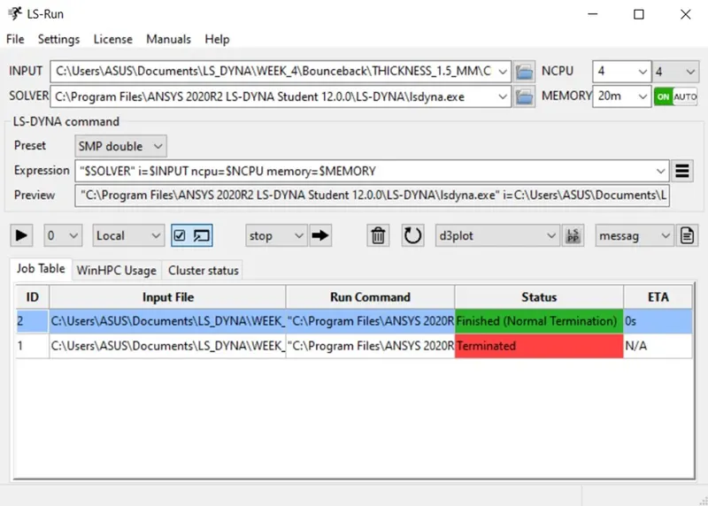
- Simulation
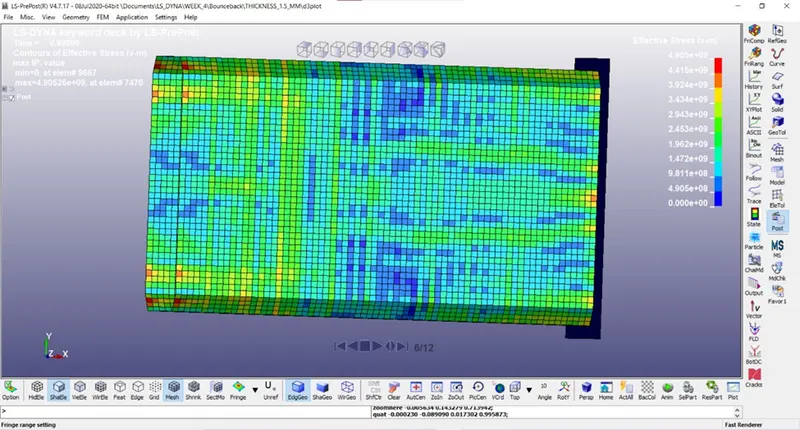
- Results
Acceleration plot of a node in the middle of crash box
Thickness 1.2 mm
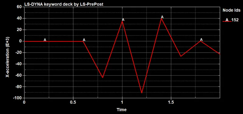
Thickness 1.5 mm
Energies plot
Thickness 1.2 mm
Thickness 1.5 mm
|
Parameter |
1.2 mm |
1.5 mm |
|
Stress along X |
5.087E+09 (g mm ms2) |
6.908E+09 (g mm ms2) |
|
Strain along X |
9.183E-01 |
8.012E-01 |
CONCLUSION
It is clear that 1.5 mm thickness posses greater stress value and less strain rate as compared to the 1.2 mm thickness model.