Week - 4 - Crash Box Simulation
Objective:
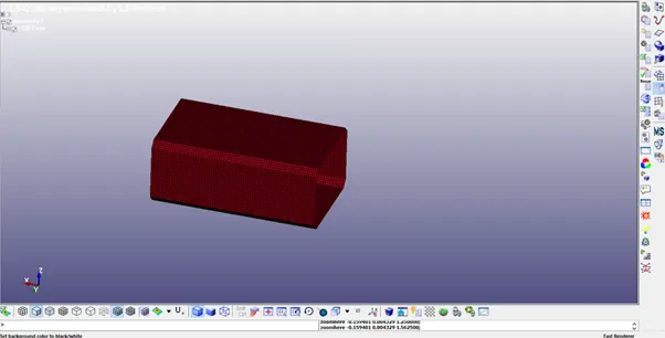
In this assignment, the student needs to simulate a crash test for a crash box for which mesh is given. A crash box is a highly energy absorbing structure that crashes on application of loads and reduces impact on other components nearby. A full-fledges crash box is a highly sophisticated design but, in this case, we will go with a rectangular channel which can thought of as the simplest crash box.
Here are the different assumptions and information required:
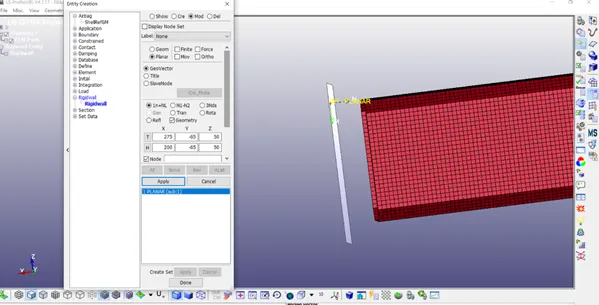
- The crash box should crash into a rigid wall created using *RIGIDWALL_ keyword. Check the manual to understand and create a rigid wall.
- Material for the crash box is steel. The simulation needs to be started using elastic material to verify its correctness and later a nonlinear material card data will be provided. Thickness of the crash box is 1.2mm.
- Initial velocity for the crash box should be around 50 kmph
- The unit system to be used is gm-mm-ms
- The simulation should satisfy either of the two situations - (1) It crashes on the rigid wall and re-bounces completely or (2) it buckles and folds in the axial direction so as to come in self-contact.
- Once the simulation is completed and results as asked for below is collected, run another simulation by increasing the thickness of the crash box from 1.2 to 1.5mm.
Deliverables:
- Input.k file and output files (d3plot, glstat, sleout, rcforc)
- Animation of the final simulation
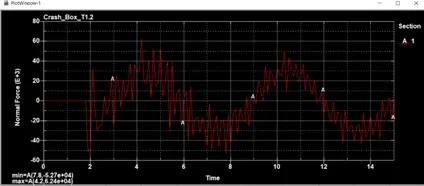
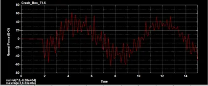
- Cross-sectional force generated in the middle of the crash box (along its length)
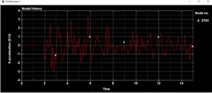
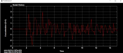
- Acceleration plot of a node in the middle of the crash box (along its length)
- Maximum directional stress and strain along the length of the crash box (X strain, Y strain etc)
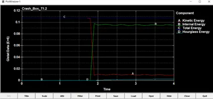
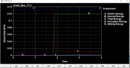
- Plot of all energies (total, internal, kinetic, hourglass, sliding)
- Compare the accelerations and stress/strain plots of 1.2/1.5mm crash boxes.
Procedure:
1. Open the given (new_crash_box.k) input keyword file in Pre Post of LS-DYNA.
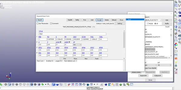
- Create the material card (Keyword-MAT- 024 PIECEWISE LINEAR PLASTICITY) for steel with values in gm – mm – ms.
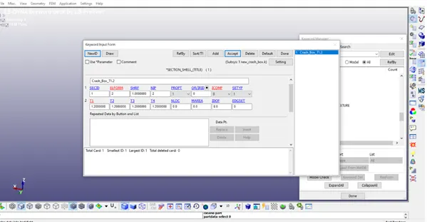
- Create a Section for the shell elements in the crash box (SECTION - SHELL) with thicknesses 1.2 & 1.5
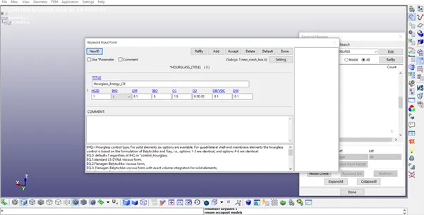
- Create Hourglass card with IHQ = 1.
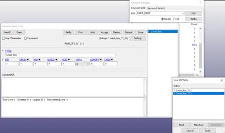
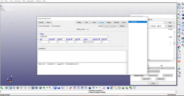
- Create Part keyword – with Material Id, Section Id & Hourglass Id.
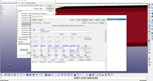
- Create a contact interface for the crash box by selecting the crash box part as a slave.
- Create a Rigid wall-normal in the x-axis.
8. Create Node set for Velocity (all the nodes) & fix the other end.
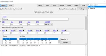
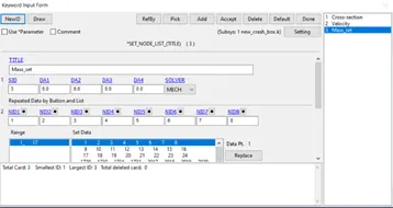
9. Assign Initial velocity of 50kmph – 13.8889 mm/ms
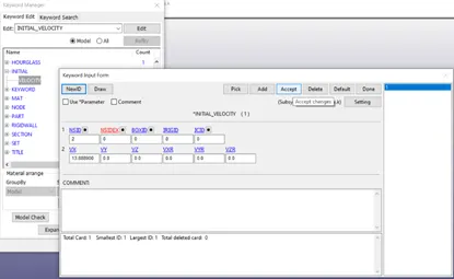
10. Create CNRB_SPC for the fixed end also applying boundary conditions to move only in x-axis
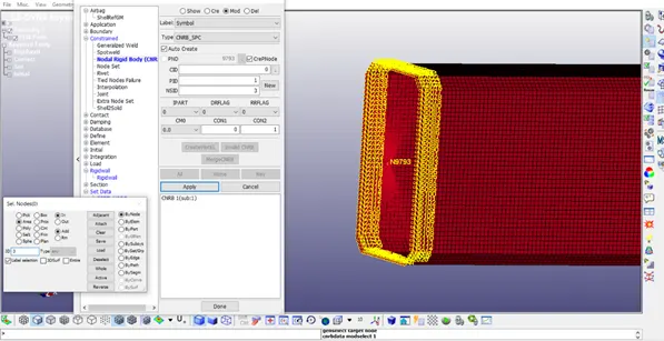
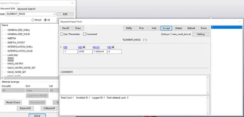
11. Set mass for node 9793 created in the above step.
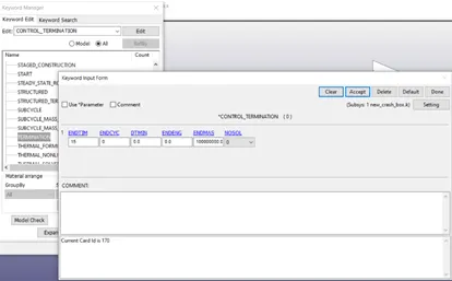
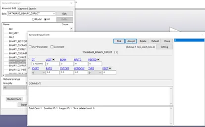
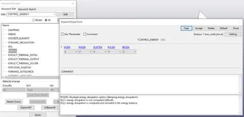
12. Set the ENDTIM in control termination, DT in DATABASE_BINARY_D3PLOT, and also create the Control Energy card as follows
13. Add the required ASCII files in the Database Keyword.
14. Save the Keyword file as (Crash_Box_T1_2) in new folder and the run the keyword file in LS – Run.
15. Open LS – PrePost, Import the D3 plot file created during the simulation.
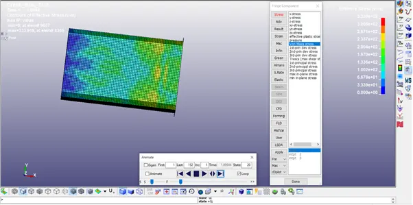
16. In the Fringe Component option, Select Von-mises stress for the contour plot and save the von mises animation videos
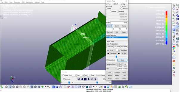
17. Cross-sectional force generated in the middle of the crash box (along its length) – Select Section plane in Model & Part – Select a node in the middle and select NormX to cut the geometry then Select force – normal force – plot to get the cross-sectional force.
T1.2
T1.5
18. Acceleration plot of a node in the middle of the crash box (along its length)
In History graph – Nodal, select a node in the model to plot the acceleration curve.
T1.2
T1.5
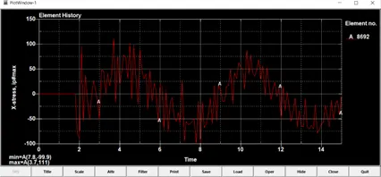
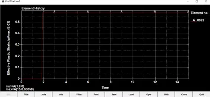
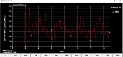
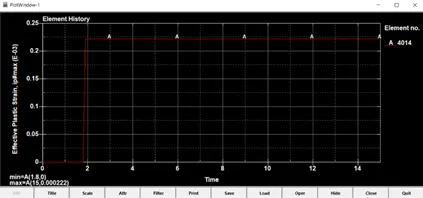
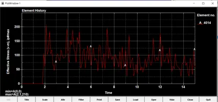
19. Maximum directional stress and strain along the length of the crash box (X strain, Y strain etc)
T1.2
T1.5
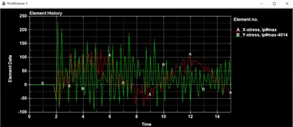
X – min (8.5, -78.7) max (5.3,126)
Y – min (4.8, -91.1) max (2.1,230)
20. Plot of all energies (total, internal, kinetic, hourglass, sliding)