Week - 4 - Crash Box Simulation
Objective: To perform crash box simulation for different thickness values
- 1.2 mm
- 1.5 mm
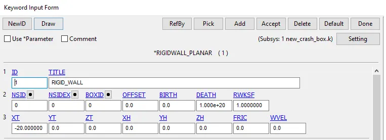
- The crashbox should crash into a rigidwall created using *RIGIDWALL_ keyword. Check the manual to understand and create a rigidwall.
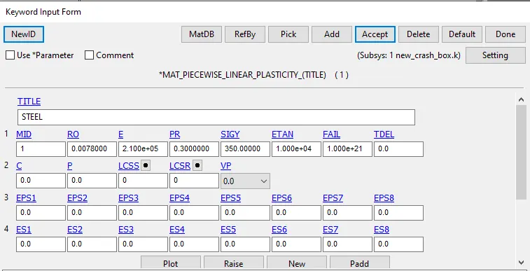
- Material for the crashbox is steel. The simulation needs to be started using elastic material to verify its correctness and later a nonlinear material card data will be provided. Thickness of the crashbox is 1.2mm.
- Initial velocity for the crashbox should be around 50 kmph
- The units system to be used is gm-mm-ms
- The simulation should satisfy either of the two situations - (1) It crashes on the rigidwall and rebounces completely or (2) it buckles and folds in the axial direction so as to come in self-contact.
- Once the simulation is completed and results as asked for below is collected, run another simulation by increasing the thickness of the crashbox from 1.2 to 1.5mm.
Outputs and Results
- Input .k file and output files (d3plot, glstat, sleout, rcforc)
- Animation of the final simulation
- Cross-sectional force generated in the middle of the crashbox (along its length)
- Acceleration plot of a node in the middle of the crashbox (along its length)
- Maximum directional stress and strain along the length of the crashbox (X strain, Y strain etc)
- Plot of all energies (total, internal, kinetic, hourglass, sliding)
- Compare the accelerations and stress/strain plots of 1.2/1.5mm crashboxes.
Procedure
1.To create a rigid wall for the simulation for crash and this was done Keyowrd manager-->All-->Rigid Wall-->Planar
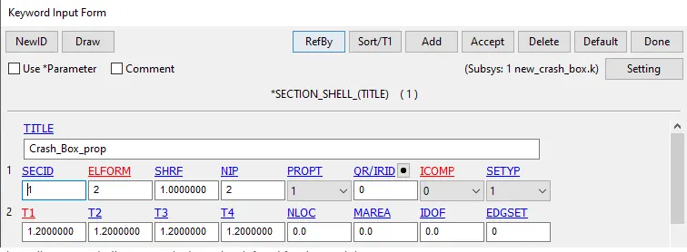
2.Now the shell section were created for the part for assigning the thickness to the part
Keyword-->All-->Shell Section
3.After this material was to be assigned to the model, it was assigned through Keyword-->all-->Mat-->24
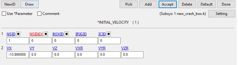
4.Now Velocity was to be assigned to the model this was done through keyword-->All-->Initial-->Velocity
As we want the box to move in X direction along the wall the Velocity of -13.89 mm/ms was assigned
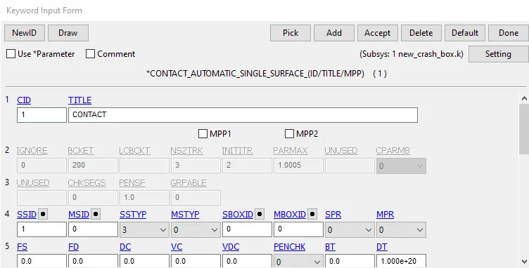
5.Now the Contact was to be asigned for the model for crash to happen it was assigned using Keyword-->all-->Contact-->Automatic Single Surface
6.Now end time and DT was to be assigned to the model so this was done Keyword-->all-->Temination,Binary D3 Plot,ASCII Files
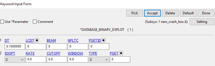
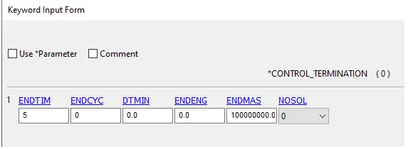
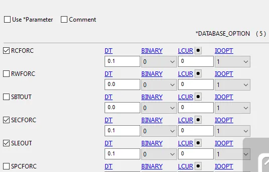
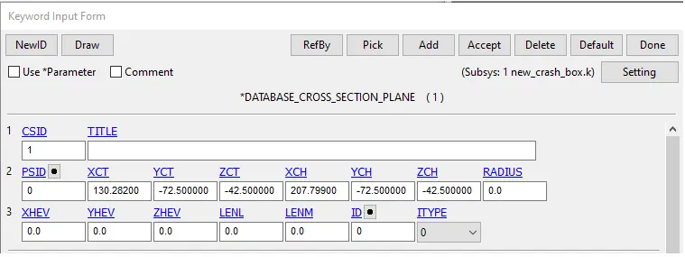
7. For Calculating the Cross sectional forces at the Midlle the Cross section was created using the Keyword-->all-->Database-->C/S plane
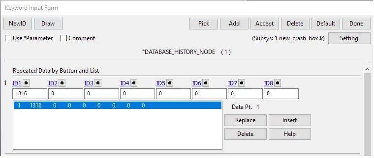
8.After this for nodal accelaration at the middle of Box was to be calculated hence we needed to create a output block for the same For creating this,keyword-->all-->Database-->History
9.Post proceessing
Case1: 1.2 mm
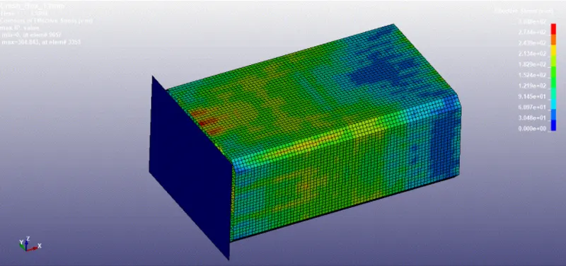
The above is von misses stress for the Case 1
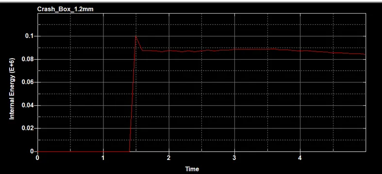
We can see that internal energy increases when the Box comes in contact with wall
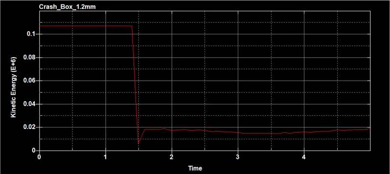
The Kinteic is high during starting and reduces during Crash
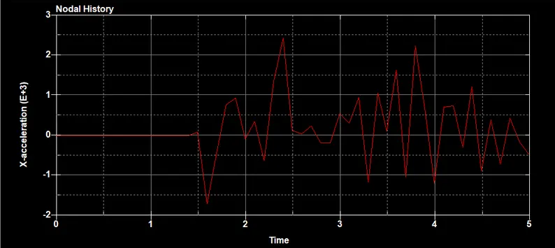
The Acceleration of the Node is plotted along the length and Peak value is about 2.4 gm
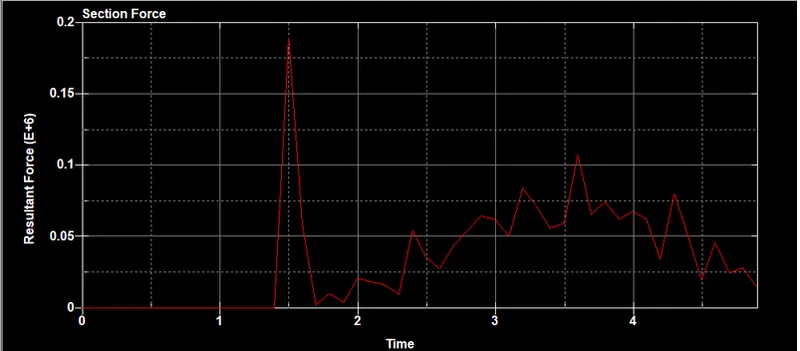
The section force is plotted with respect to time
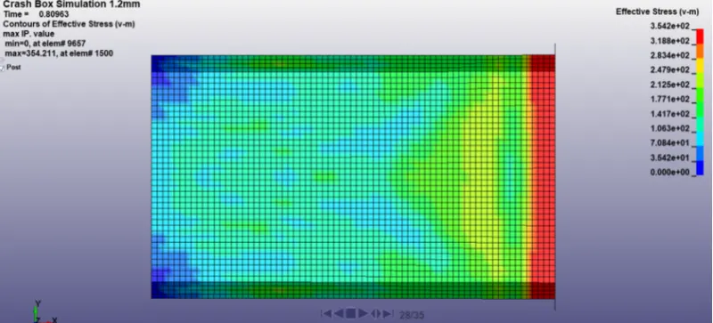
The above is the Von misses stress for the Case 1
Case 2
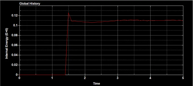
Internal energy increase during impact
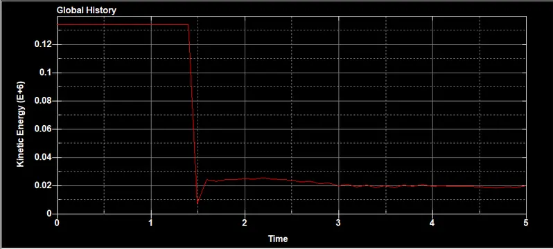
Kinetic energy reduces on the impact on the rigid wall
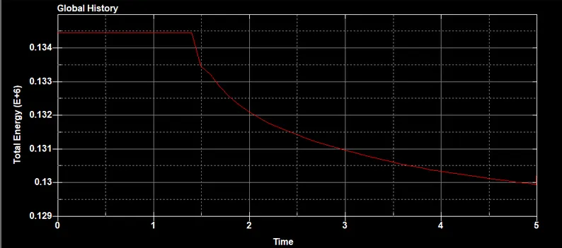
Kinetic energy gets converted into Internal energy
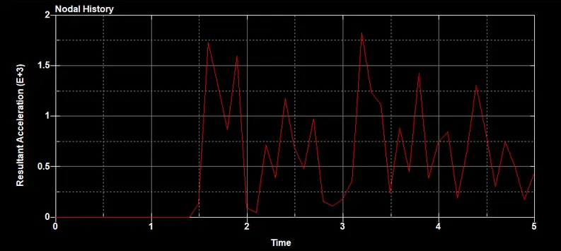
The nodal Acceleration is less than case 1,The peak value is about 1.6 g
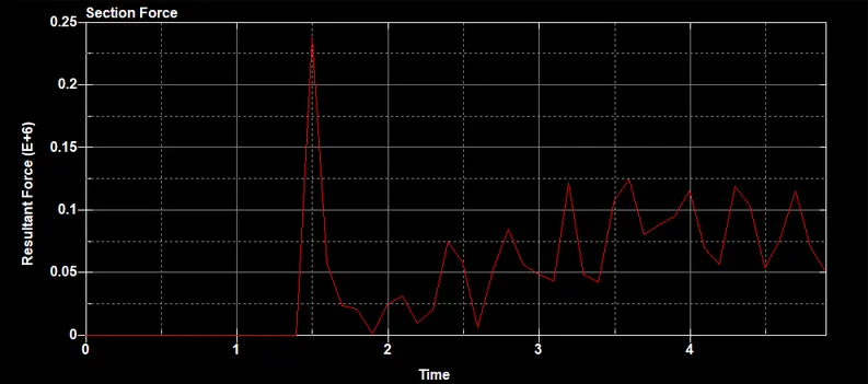
Sectional Forces at the Center are high during imapct and reduces with with respect to time
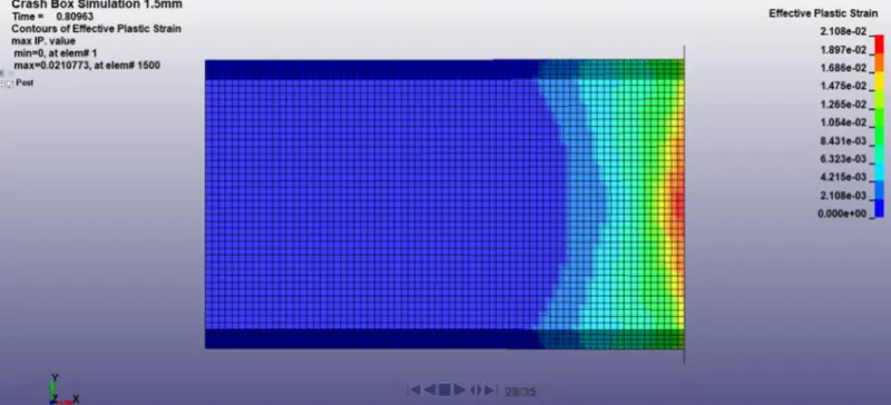
The Above is the Von misses stress for the Case 2
Conclusion : Hence Completed case set up for the both Condition by creating keywords and ran the simulation and Grabbed required results from the simulation