Week 4 - Conformal Meshing of an Electronic enclosure assembly
Aim : To create a conformal mesh for the given icepack model of an electronic enclosure assembly.
Introduction :
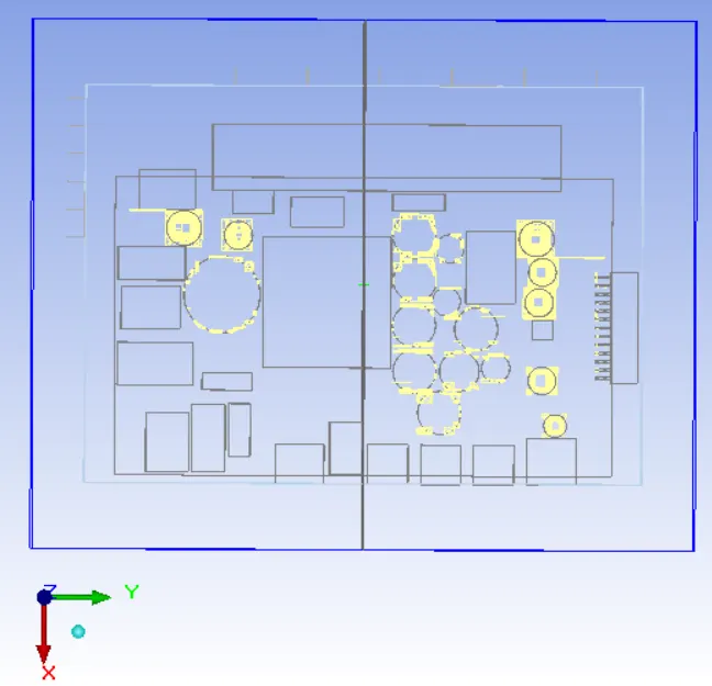
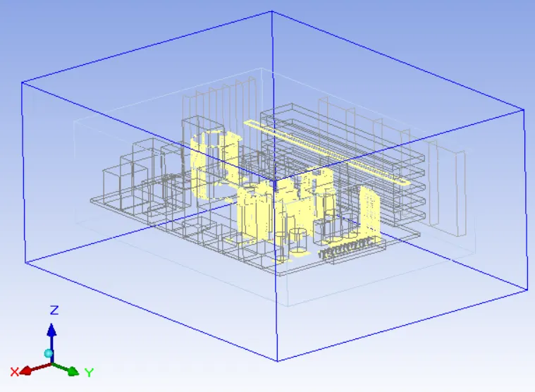
In present project conformal mesh is created for the icepak model shown in the image attached below
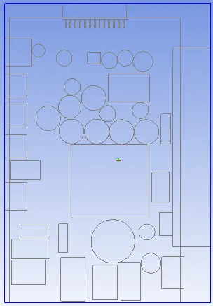
Description
Meshing discretizes the physical domain into elements. For each of these elements the governing equations for flow and heat transfer are solved to obtain the discretised solution field in the cabinet.
For CFD SSimulation, the meshing should be good quality to obtain a converged and appropriate solution. If mesh is too coarse then we may face a discretisation error (incured as a result of converting continuous Partial differential equations into algebraic equations) becomes too large and the solution becomes inaccurate. On the other hand if the mesh is too fine, the computational time may become unacceptable.
ANSYS Icepak automates the mesh generation process such that near the object boundaries (like wall, the velocity and temperature gradients are possibly higher) more elements are placed and in open spaces between the objects less elements are placed. The user can affect this mesh generation process by setting the various parameters available in Mesh control window of ANSYS Icepak. These parameters can be used to modify the mesh globally or locally.
Meshing
The following settings are applied in the Mesh control window to generate conformal mesh for the given Icepk model:
1. Mesh type: Mesher-HD
Generates a Hex-dominant mesh
2. Concurrency: 1
This option can be used to control the number of assemblies being meshed simultaneously when the option "Mesh assemblies separately" is turned on.
3. Mesh units: mm
Set units of elements size to mm
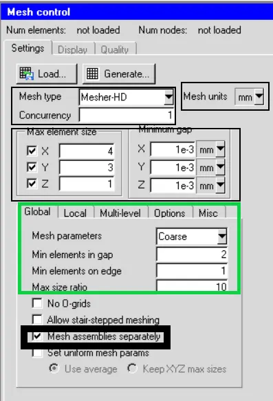
4.Maximum element size
X:4mm
Y:3mm
Z:1mm
The default values (about 1/20 of the cabinet dimension in respective directions) are adopted.
5.Minimum element size
X:1e-3mm
Y:1e-3mm
Z:1e-3mm
The option specifies the minimum distances between objects in the model along X,Y and Z coordinate directions.
6 Global mesh setting
6.1 Mesh Parameters : Coarse
6.2 Minimum elements in gap : 2
This option specifies the minimum of elements along the edge of each object.
6.3 Maximum size ratio : 10
This option specifies the maximum ratio between the sizes of two neighbouring elements, in the entire domain.
6.4 No O-grid: Not Enabled
This option informs the icepak meshers whether O-grids are to be placed around the objects in the models.
6.5 Allow stair-stepped meshing: Not Enabled
This option informs the icepak mesher whether stair-stepped meshing is permitted. If this option is enabled, the geometries of the objects in the model are approximated by the mesh since the projection and decomposition steps during 3D cut cell meshing are disabled. Stair-stepped meshing will have reduced number of elements in the mesh and can be used where resolving the geometry of objects is not important.
6.6 Mesh assemblies separately : Enabled
6.7 Set uniform meshes params : Not enabled
has two options
a.Use average creates a uniform mesh with the same mesh size in all coordinate directions. The mesh size is computed by averaging the specified max element sizes.
b.Keep XYZ max sizes creates a uniform mesh in each coordinate direction using the corresponding max element size. The resulting mesh has constant spacing in each coordinate direction but the spacing can be different if the max element sizes are different. Using uniform mesh params results in lower mesh count and improved quality. It is recommended to use uniform meshing params when multi-level meshing is used. If this option is enabled then 3D cut cells and stair step meshing ignores the object-0based params to keep the mesh uniform and generates better quality meshes. To provide object-based control on meshing, meshing levels can be used for the objects defined under Edit levels.
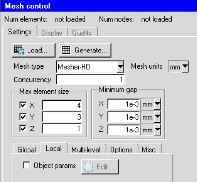
7. Local setting: Not Enabled
This can be used to modify the mesh locally (on or near the objects in the model). In the present project, no modification is made to mesh locally (on or near the objects in the model).
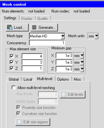
8. Multi-level : Not enabled
Additional options for improving the mesh are as follows:
-
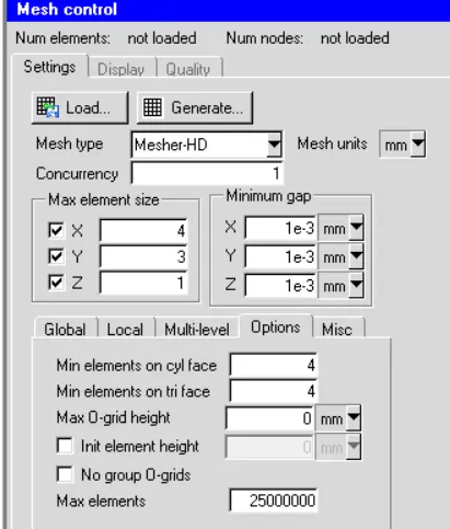
If your model includes a small number of objects, and the element count or spacing on all of them is low, you can use the Init element height option to turn on O-grid cocooning and place graded elements on the faces of all objects. This option should be used only when the number of objects is not too large; otherwise, the mesh count can become very large. See Global Refinement for a Hex-Dominant Mesh for details.
-
In some cases, setting Max O-grid height to a small enough value relative to the object size will yield better mesh quality by localizing the cocooning action of the mesher. Note the value of Max O-grid height should be higher than that of Init element height, and that a value of 0 for Max O-grid height leaves the O-grid height unbounded.
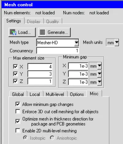
MISC
9. Visual Inspection
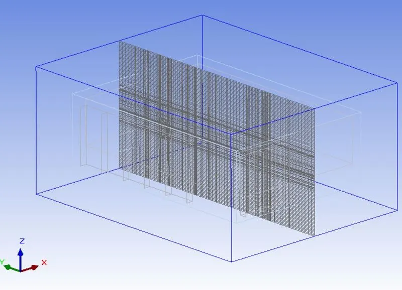
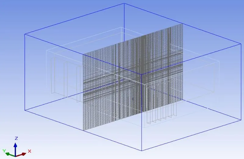
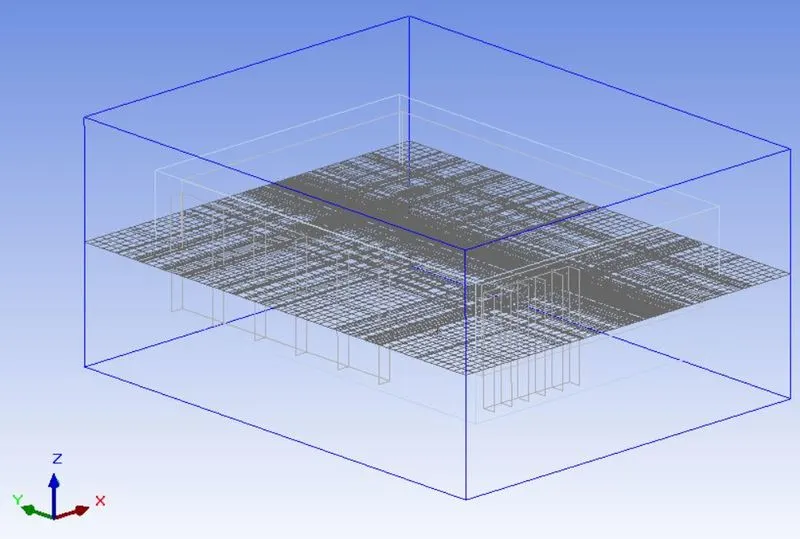
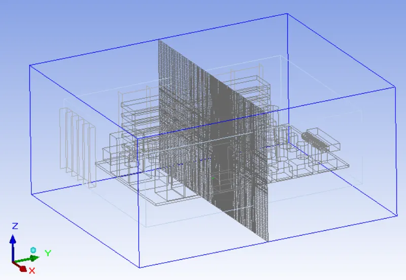
Visual Inspection is a very important step that must be performed after mesh generation in order to ensure that the mesh model captures all the design inputs. The images attached below show the mesh along different cut-planes and on the surface of all the objects within the enclosure.
10. Quality
A good quality mesh guarantees the best analysis results for the problem, minimizes the need for additional analysis runs, and improves your predictive capabilities. The mesh should be fine enough to resolve the primary features of the problem being analyzed. The mesh resolution depends on the boundary mesh from which you start and the parameters controlling the generation of the interior mesh. In a high-quality mesh, the change in size from one face or cell to the next should be minimized. Large differences in size between adjacent faces or cells will result in a poor computational mesh because the differential equations being solved assume that the cells shrink or grow smoothly.
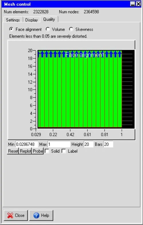
Minimum face alignment index for the mesh is approximately 0.0286748. However mesh elements having face alignment index below 0.05 are severly distorted which might create a problem for solver.
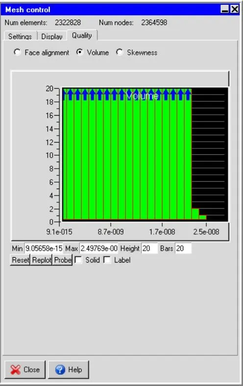
Minimum Volume of mesh is approximately 9.05658e-15. However for single precision solver the volume mesh elements should be greater than 1E-13 m^3. mesh needs to be modified.
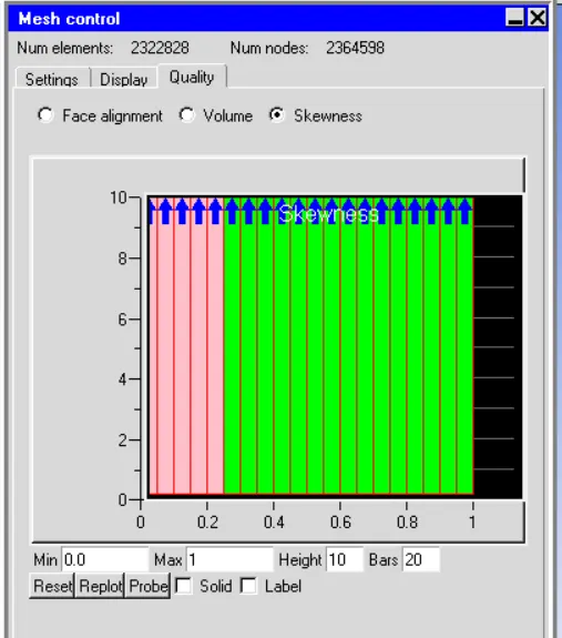
The skewness of a face/cell indicates how close to ideal (equilateral or equiangular) it is. A face/cell with a skew of 1 is equlateral/equiangular whereas a face/cell with a skewness of 0 is degenarate.
Conclusion:
In the present project, a confirmal mesh was created for the given Icepak model. The mesh was viewed along different cut planes and on the surface of all objects within the enclosure. Quality check of the mesh revealed that several elements in the mesh have poor quality. Hence present mesh must be modified in order to avoid any problems during solution, which might be due to poor quality of mesh elements.