Week 4 - CHT Analysis on Exhaust port
Introduction:
In the field of fluid dynamics where predicting the right results with right assumptions is a really big deal. For resolving this CFD is a tool that is doing the same via solving several governing equations like conservation of momentum – Navier stokes equation, conservation of energy etc. at the same time. It is a sub-part of fluid dynamics that visualise the flow of fluid and its relative physics. So, we are solving the fluid challenge of Ahmed body with Ansys software by starting from pre-processing and ends with post-processing by doing solving in between both of them. This is a problem that is basically based on the analysis of the velocity and flow pattern of the fluid over the Ahmed body. On the basis of the velocities of the fluid flow and the pattern that it follows around the geometry, we have to validate the same with present research data from several research papers.
Procedure
To get the desirable results we go through 3 major steps in the same sequel and based on the steps we followed during whole setup we got the results.
- First of all, open the workbench
- Drag the Fluid Flow (fluent) part in the Project schematic window
- So, via going through Geometry option open the Space claim
- Go to the open – new – go to geometry location – select open command
- By following step 4 we will able to open the geometry in the space claim
- Now choose the required volume from the whole geometry to do further process efficiently.
- Check for any overlaps and the intersections that cause problem in the meshing.
- After verifying the model and then close the window.
- Now open Ansys Meshing and let the geometry upload.
- Then firstly name all the parts of the model.
- Then from the Tree right click on mesh and tap "Generate mesh"
- Set the sizing of the meshing from its detail and then repeat the step 11.
- After verifying the mesh, close the Ansys Meshing window.
- Now open Ansys fluent window by clicking over ‘Setup’ and let the geometry upload.
- For verifying the check click of ‘Checks’ option and see the results in console.
- Go to the General and set the case accordingly as mentioned in the challenge
- As we are dealing with temperature so mark the Energy option and chose the viscous flow option to define the fluid flow.
- After this set the Boundary conditions.
- Generated the graphs that we want to observe during the case run.
- With this go to the results and create a plan in from the centre of the body and allow to show the velocity contour pattern over it during the case run time.
- In addition to this, from ‘solving’ section also select animation for the same velocity contour.
- The initialize the case
- Set the total no. of iteration.
- Click calculate to make simulation run
- As the simulation completed close the tab and do the postprocessing as analyse the contours and plots.
- For this select the plane slice that is situated in the centre of the geometry and over it we have to perform the contour analysis.
- Close the tab after extracting useful results.
- Save the case and cut the software.
Results:
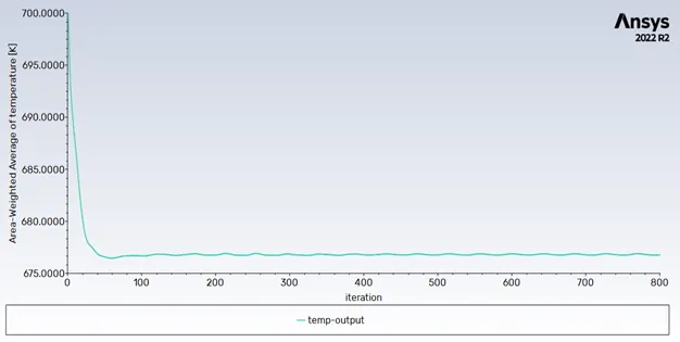
Word file with all snapshots is attached below.
Thankyou
Anubhav