Week 4 - CHT Analysis on Exhaust port
Aim: Steady-state CHT analysis on Exhaust port at an inlet velocity of 5m/sec
Objective: The objectives will mainly focus on
- Give a brief description of why and where a CHT analysis is used.
- Maintain the y+ value according to the turbulence model and justify the results.
- Calculate the wall/surface heat transfer coefficient on the internal solid surface & show the velocity & temperature contours in appropriate areas.
- How would you verify if the HTC predictions from the simulations are right? On what factors does the accuracy of the prediction depend?
Introduction: Conjugate heat transfer analysis is based on a mathematically structured problem, which describes the heat transfer between a body and a fluid flowing over or inside it as a result of interaction between two objects. At the matching interface, the details are provided for temperature distribution and heat flux along the interface eliminating the need of calculating the heat transfer coefficient. Moreover, the heat transfer coefficient can be calculated later.
One of the simplest ways to realize conjugation is through numerical methods. The boundary condition for the fluid and solid interface is set and solved through iteration methods. There are no right guesses for the values of the initial boundary condition for the convergence except through the hit and trial method.
Application: The conjugate heat transfer methods have become a more powerful tool for modeling and investigating nature phenomena and engineering systems in different areas ranging from aerospace and nuclear reactors to thermal goods treatment and food processing from the complex procedures in medicines to ocean thermal interaction in metrology.
CHT in recent years has significantly improved the cooling performance of electronic equipment such as the design of heat sinks and the design of heat exchangers for the waste treatment plant. One such application of CHT is the exhaust port system.
Solving and modeling approach
- The exhaust port was modeled into the Spaceclaim.
- The exhaust port is a three-dimensional model containing four inlets and one outlet. Despite having isothermal boundary conditions and a uniform flow rate at the four inlets, the model cannot be cut into two halves to save computational time because of its asymmetrical nature. Therefore the whole model is discretized and is considered for meshing.
- CHT analysis requires both the solid and the liquid volume under consideration, Spaceclaim gives an option of volume extract for selecting edges for fluid volume.
- Both the solid volume and liquid volume are copied into one component.
- Share topology is created.
- Spaceclaim gives an option for share coincident topology, when share coincident topology is selected and executed, the mesh from the fluid volume and the solid volume are said to be conformal with each other which is a requirement for CHT analysis.
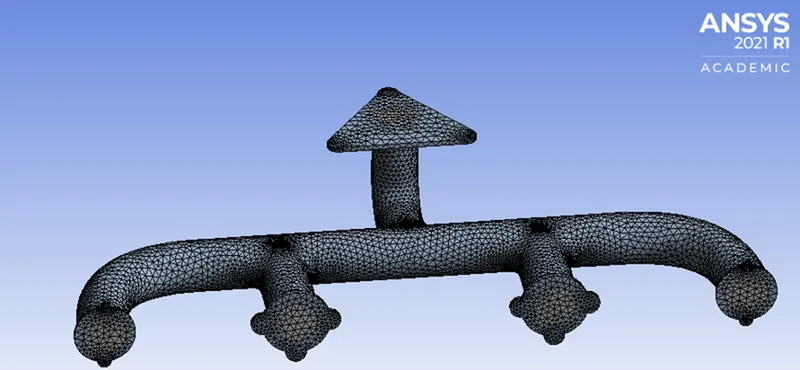
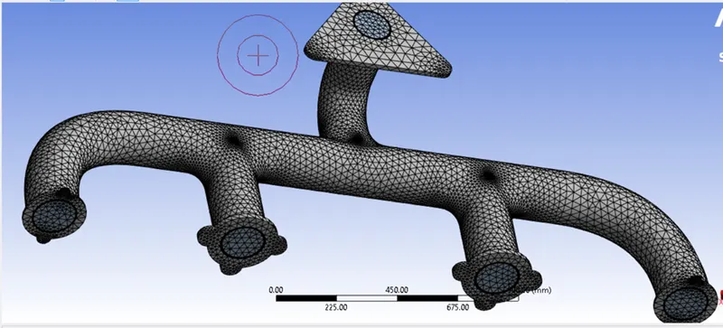
- The exhaust port is loaded into the meshing window and then simulated for baseline mesh and the refined mesh.
- The named selections are created ( inlet, outlet, outer wall convection)
- The necessary contour images and graphs are studied to understand the behavior of temperature, velocity, and surface heat transfer coefficient at the interface.
Pre-processing and solver setting
Baseline mesh
The geometry is loaded into Spaceclaim
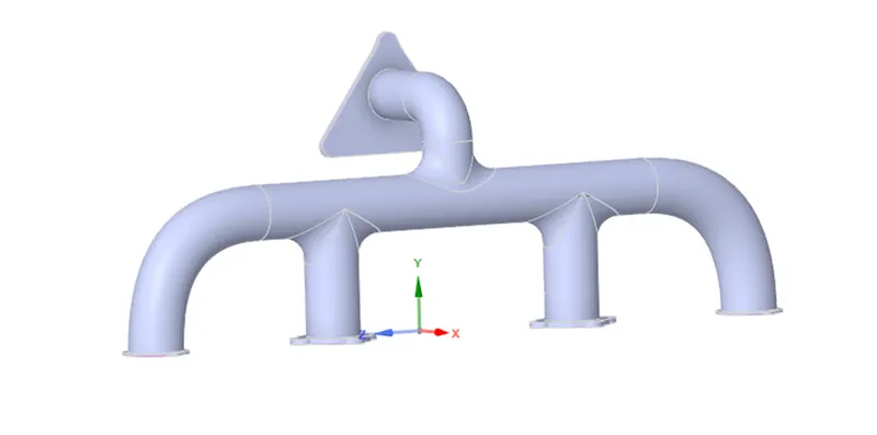
Fluid volume extraction
It is the process of extracting the fluid volume from the solid volume.
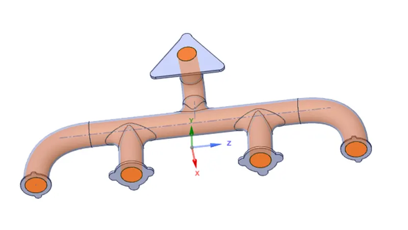
Share topology
It is the process of sharing information from fluid volume to solid volume. It plays important criteria in CHT analysis.
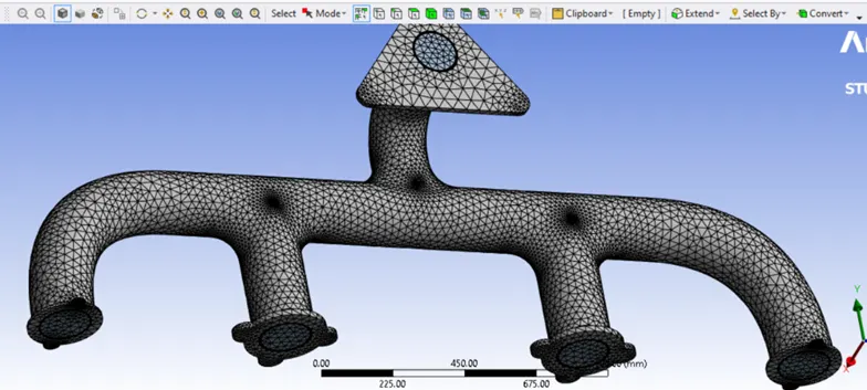
Meshing: It is the process of discretizing the geometry into a small number of volumes containing nodes. Since the geometry is complex and the mesh is unstructured therefore the finite volume scheme is used as a discretization scheme.
In this case, the default element size of ANSYS-FLUENT is used (150mm).
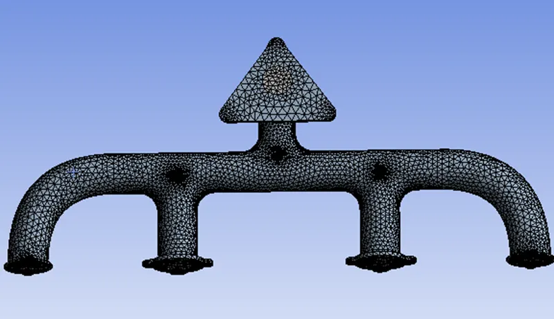
Mesh statistics
|
Number of elements |
135747 |
|
Number of nodes |
27104 |
Named selection
inlet boundary condition (velocity inlet) @ 5msec
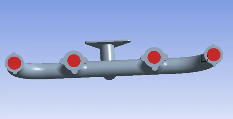
Outlet (Pressure outlet) Gauge pressure 0Pa
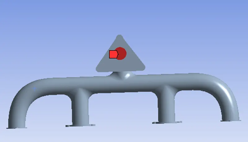
Outer wall convection (Heat transfer coefficient 20 W/m^2K free stream temperature 300K
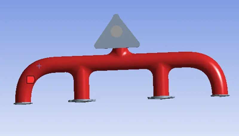
The flanges around the inlet and the component encompassing the outlet are adiabatic (no heat transfer takes place through these walls).
Setting up of physics and boundary conditions
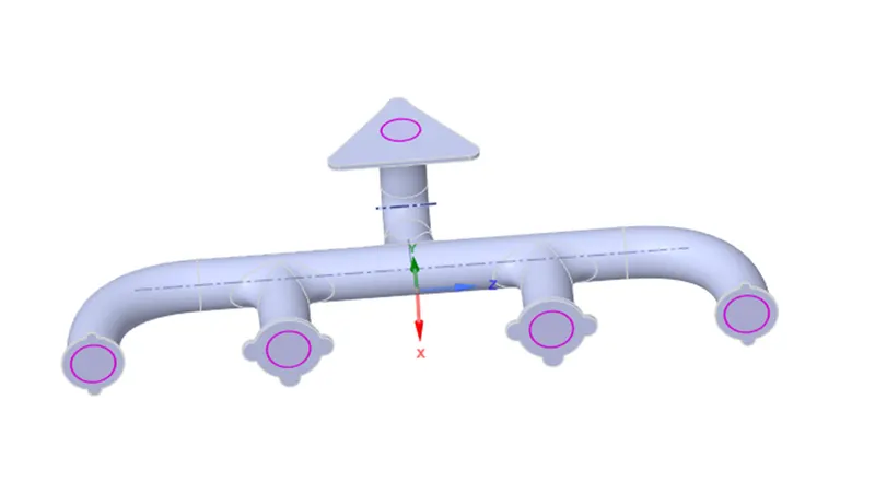
The geometry orientation in the setup window. The blue-coloured lines are inlet, and the red-coloured lines are outlet.
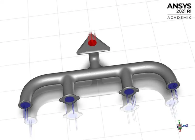
Set up
The different boundary conditions are listed below
Inlet boundary condition
- Type: Velocity inlet
- Velocity magnitude : 5m/sec
- Temperature: 700K
Outlet boundary condition
- Type: Pressure outlet
- Gauge pressure: 0Pa
Outer wall convection
- Type: wall
- Thermal condition: convection
- Heat transfer coefficient: 20W/m^2K
The rest boundary condition values are set up as default values in ANSYS-FLUENT.
- Energy equation: It is turned on.
- Viscous model: It is set to k−epsilon
Material properties
Fluid
- Material Name: Air
- Density: 1.225kg/m^3
- Specific heat: 1006.43J/kgK
- Thermal conductivity: 0.0242W/mK
- Viscosity: 1.7894e−05kg/m−sec
Solid
- Material Name: Aluminium
- Specific heat: 871J/kgK
- Thermal conductivity: 202.4W/mK
SIMPLE METHOD
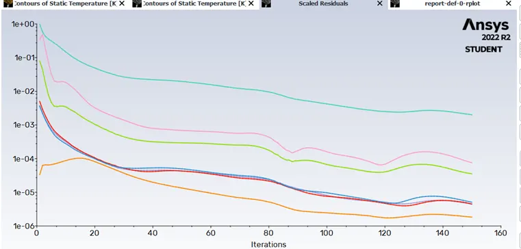
Residual plot
Surface heat transfer coefficient
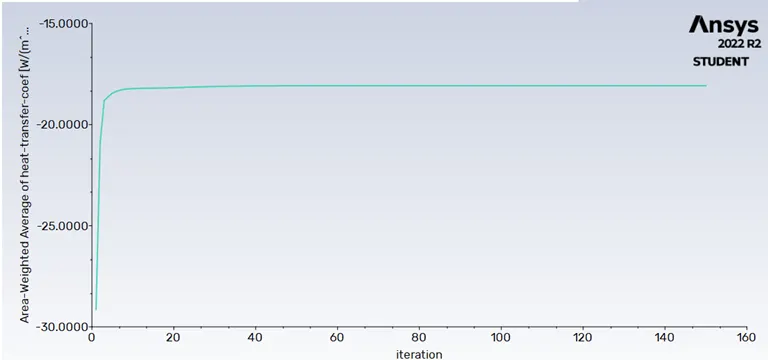
Surface heat transfer coefficient value: -18.7213 W /m2K
CHT analysis of exhaust port with finer mesh
First refinement
Element size: 90mm
Since the value of the heat transfer coefficient takes the value of the first cell near the wall, so it can be inferred that the Y+ value will be in the viscous sub-layer which is taken to be 1.
Steps involved in calculating the first cell height.
Reynolds number= ρ∗v∗L/μ
=1.225∗5∗0.17/1.7894e−05
=58189.8960
The characteristics length is taken as the inlet dia.
Skin friction coefficient, Cf=0.058/Re^0.2
=0.00646
Wall shear stress formula, τw=0.5∗Cf∗ρ∗v^2
=0.5∗1.225∗25∗0.00646
=0.0989 Pa
Frictional velocity formula, uτ=(τw/ρ)^0.5
=0.2841msec
Now, Y+=△y∗uτ∗ρ/μ
Since Y+=1
Therefore △y=μuτ∗ρ
=0.0000514162m
=0.05141621mm
Inflation
Number of inflation layer:5
Growth rate: 1.2
Inflation option: total thickness
max thickness: =5 mm
Captured curvature is set to yes.
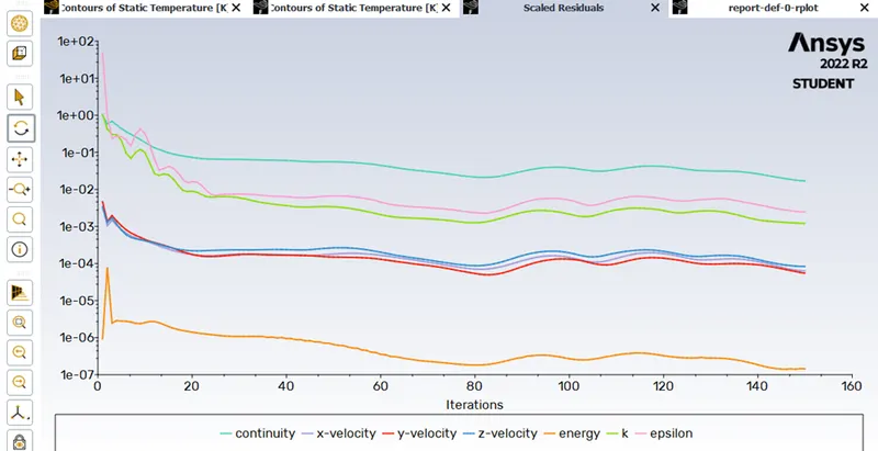
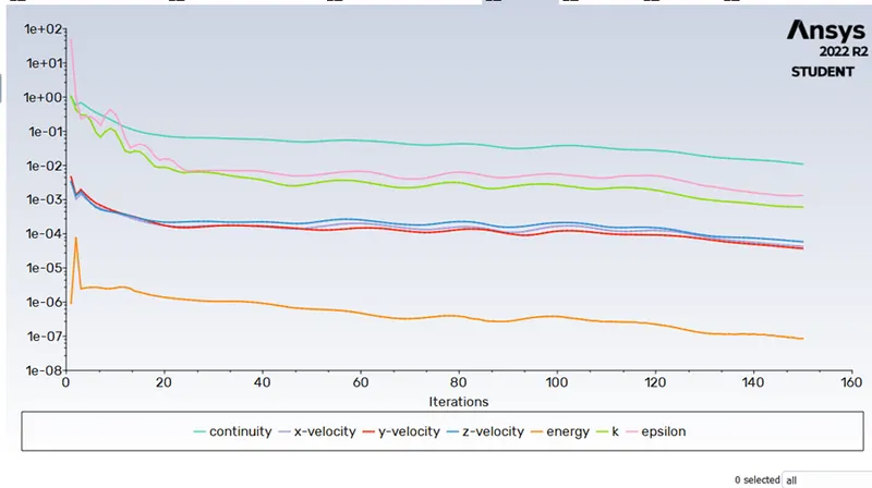
Residual plot
Surface heat transfer coefficient
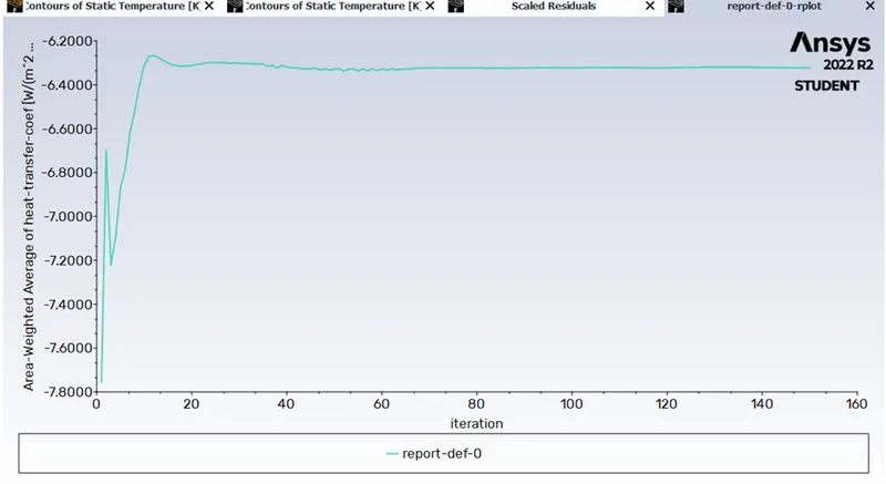
Mesh statistics and surface heat transfer coefficient
|
Element size |
90mm |
|
Number of elements |
241525 |
|
Number of nodes |
85789 |
|
Y+ |
1 |
|
Heat transfer coefficient |
-6.3125/m^2K |
Second refinement
Element size: 80mm
Residual plot
Surface heat transfer coefficient
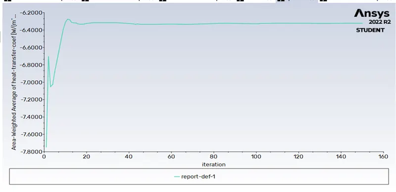
Mesh statistics and surface heat transfer coefficient
|
Element size |
80mm |
|
Number of elements |
241524 |
|
Number of nodes |
85784 |
|
Y+ |
1 |
|
Heat transfer coefficient |
-6.2818W/m^2K |
Final refinement
Element size: 70mm
Number of inflation layer: 5
Growth rate: 1.2
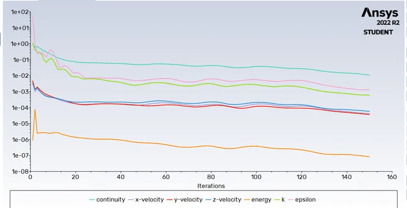
Residual plot
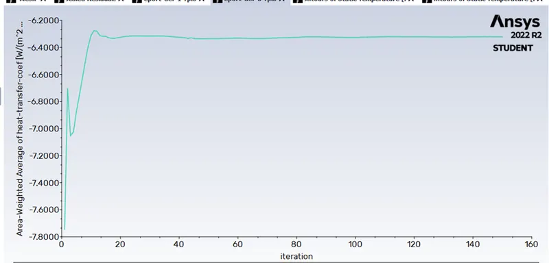
Surface heat transfer coefficient
Mesh statistics and surface heat transfer coefficient
|
Element size |
70mm |
|
Number of elements |
241524 |
|
Number of nodes |
85784 |
|
Y+ |
1 |
|
First cell height |
0.05141621mm |
|
Heat transfer coefficient |
-6.251854 W/m^2K |
Comparison of all cases
|
Element size |
Number of elements |
Number of nodes |
First cell height |
Y+ |
Inflation layer |
Surface heat transfer coefficient.(Numerical value) |
|
0.15m |
135747 |
27104 |
N/A |
N/A |
N/A |
-18.7213W/m^2K |
|
0.09m |
241525 |
85789 |
0.0000514162m |
1 |
5 |
-6.3125W/m^2K |
|
0.08m |
241524 |
85784 |
5 |
-6.281W/m^2K |
||
|
0.07m |
241524 |
85784 |
5 |
-6.2578W/m^2K |
Results
The temperature along plane-1 located at the exhaust section of the port.
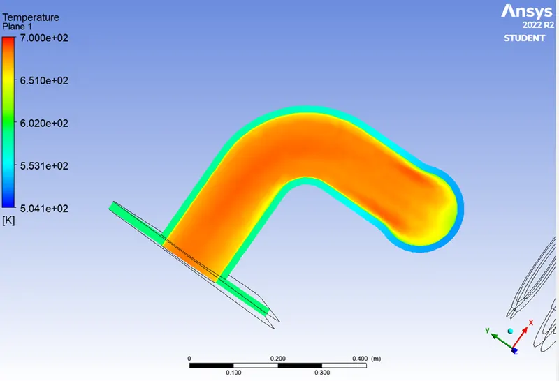
The velocity along plane-1 located at the exhaust section of the port.
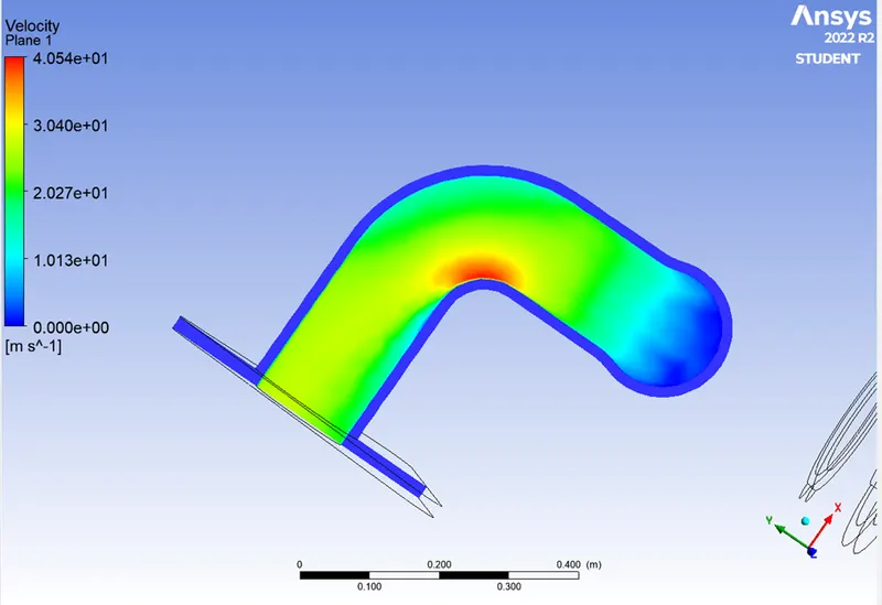
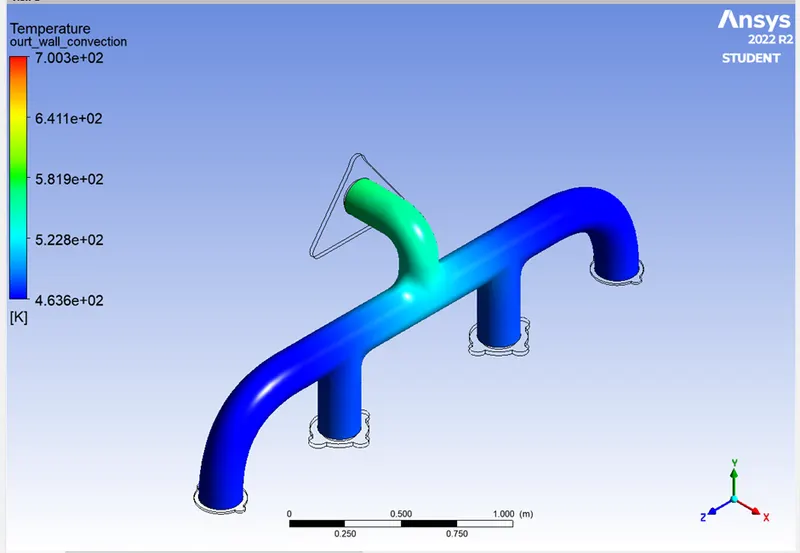
Temperature at outer convection wall.
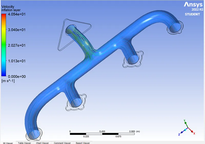
Streamline representation of velocity
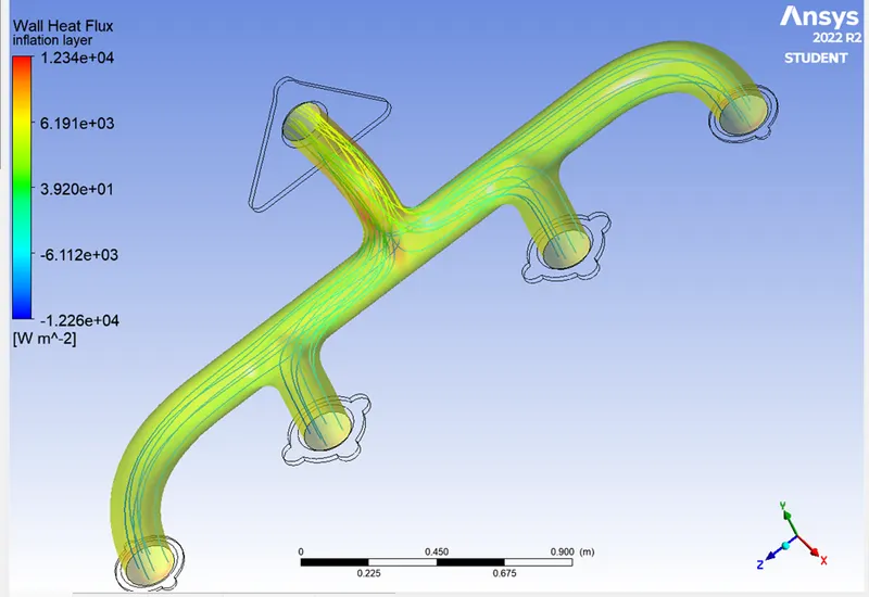
Surface heat transfer coefficient
Conclusion
- The CHT analysis on the exhaust port was simulated successfully on ANSYS-FLUENT.
- The pressure-based solver is used to discretize the whole geometry.
- Mesh refinement will cause the reduction of heat transfer coefficients.