Week 4 - CHT Analysis on Exhaust port
Introduction:
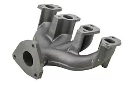
The exhaust manifold is a component that is considered part of an engine's "lungs" because
it exhales the gases produced during the combustion process and sends them out the
tailpipe to make way for fresh oxygen in each cylinder. Because the more oxygen a motor
can burn, the more power it can produce, exhaust manifolds are critical to the operation of
your vehicle.
The pressure inside the cylinder is high enough to force most of the gas out. Some exhaust
manifolds are designed to concentrate the heat of the gases in order to burn off any
residual fuel that may remain after combustion.
Q1. Give a brief description of why and where a CHT analysis is used.
Conjugate heat transfer is a type of heat transfer analysis that involves the interaction of
solids and fluids (s). Convection (between fluids) and conductive (between solids) heat
transfer, as well as forced and natural convection, are examples of this type of heat transfer.
For better understanding of thermal exchange across component and enhanced
temperature prediction technique Conjugate Heat Transfer analysis is used to analyse an
entire engine manifold on steady state condition.
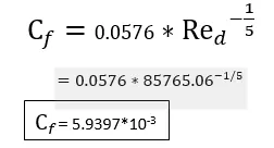
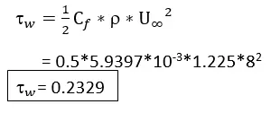
Q2. Maintain the y+ value according to the turbulence model and justify the results.
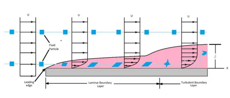
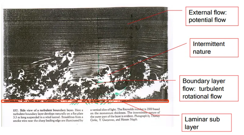
1) Reynolds number
Re > 10,000 so it is a turbulent flow
Where:


2) Nusselt number
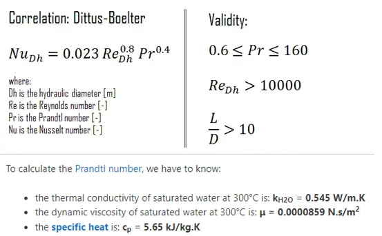
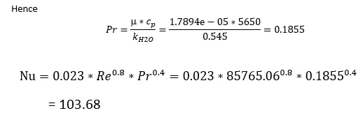
Q3. Calculate the wall/surface heat transfer coefficient on the internal solid surface & show
the velocity & temperature contours in appropriate areas.
To Calculation of heat transfer
Where:
kf is a thermal conductivity of the fluid [W/m.K]
L is the characteristic length
h is the convective heat transfer coefficient [W/m2.K]
Nu = h/ (kf /l)
h = Nu x (kf/l)
= 103.68 x0.0242/0.1566
= 16.022 w/m3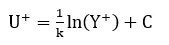
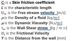
Where κ is Von Karman’s constant and is generally 0.41
C is the law of wall constant.
Q4. How would you verify if the HTC predictions from the simulations are right? On what
What factors does the accuracy of the prediction depend on?
Pre Process Approach
Geometry
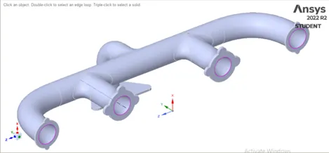
The geometry was modeled in any designing software, and the model is brought
up in Ansys Fluent Workbench Spaceclaim and can be repaired if any duplicate lines
or surfaces are present. In order to see the flow properties over the exhaust manifold first
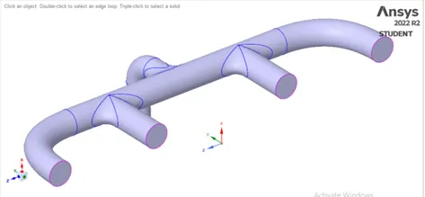
extract the volume for the given model. The volume extraction tool extracts the fluid
volume from the exhaust manifold. After extraction segregates the fluid volume and a solid
volume separately. The share tool is used in between these two volumes which will help build
proper mesh between these volumes.
 |
 |
Mesh
 |
 |
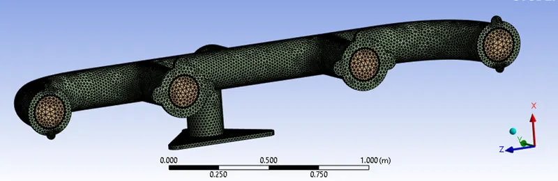
Initially we should generate the default mesh to see the mesh behaviour and based on that we
should change as per the requirements. Name the domain with inlet, outlet, and Outer wall
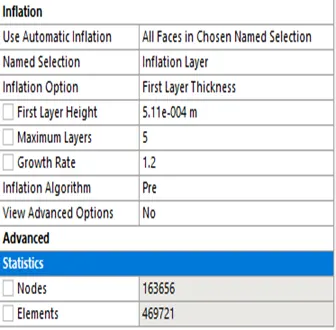
convection. For to maintain the proper Y+ value i.e. to give first layer thickness around the
fluid volume to know the flow behaviour of heat transfer coefficient.
 |
 |
 |
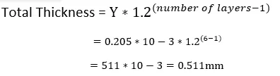
Since to know the behaviour in between the solid and fluid volume the layer will in viscous
sub layer hence the Y+ value will be <5, hence for Y+ value of 5 the first layer thickness
comes around 0.511mm. By providing this the total mesh nodes and elements has been
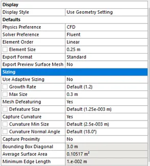
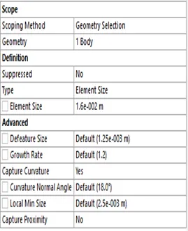
increased beyond the licence version. Hence the main model is given the mesh size of 0.25m
to control the elements and nodes for the licensed version, before moving for the set up
enable curvature. This will help to capture the flow behaviour around the corners of the
exhaust manifold.
Setup/Solution
Since the Reynolds is high which in turbulent nature, hence turbulence K-Ɛ model is used.
We need to know the temperature behaviour on exhaust manifold energy equation is taking
into consideration.
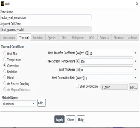
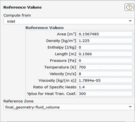
Boundary Condition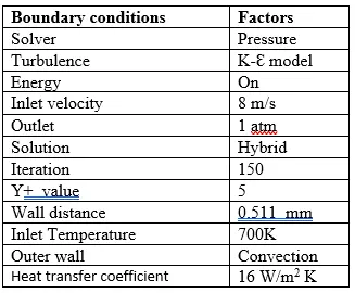
 |
 |
Post Process Approach
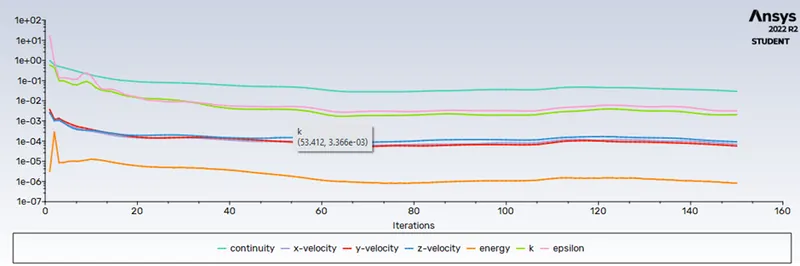
Results
 |
 |
 |
 |
 |
 |
 |
|
 |
 |
 |
|
 |
|
 |
|
 |
|
 |
|
 |
|
 |
|
 |
|
 |
|
 |
|
 |
 |
Result & Conclusion:
The CHT analysis of the exhaust is conducted to see the performance of the exhaust
manifold in its working conditions
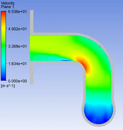
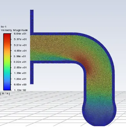
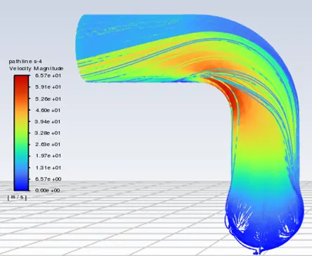
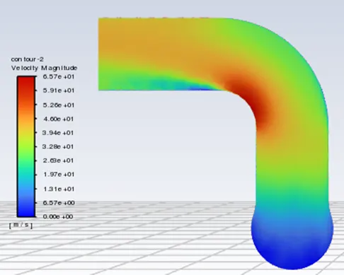
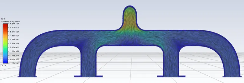
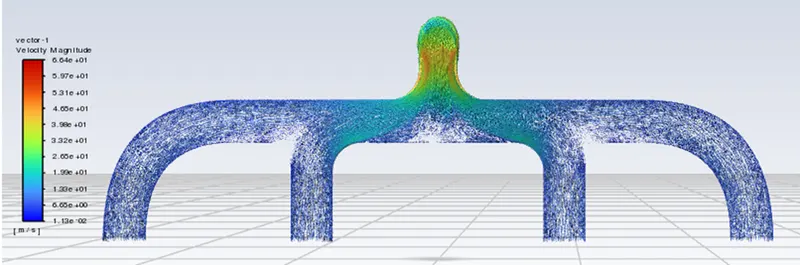
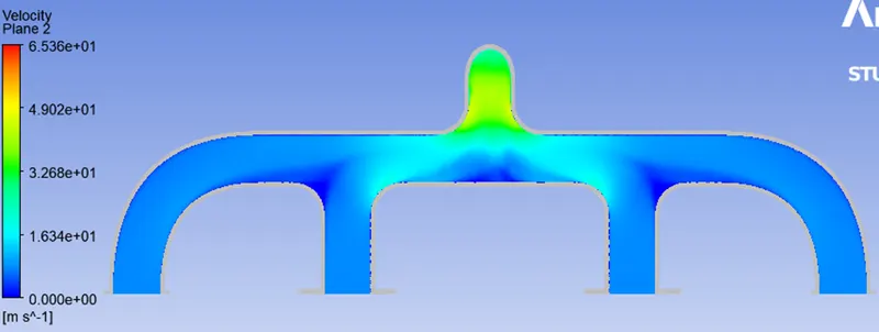
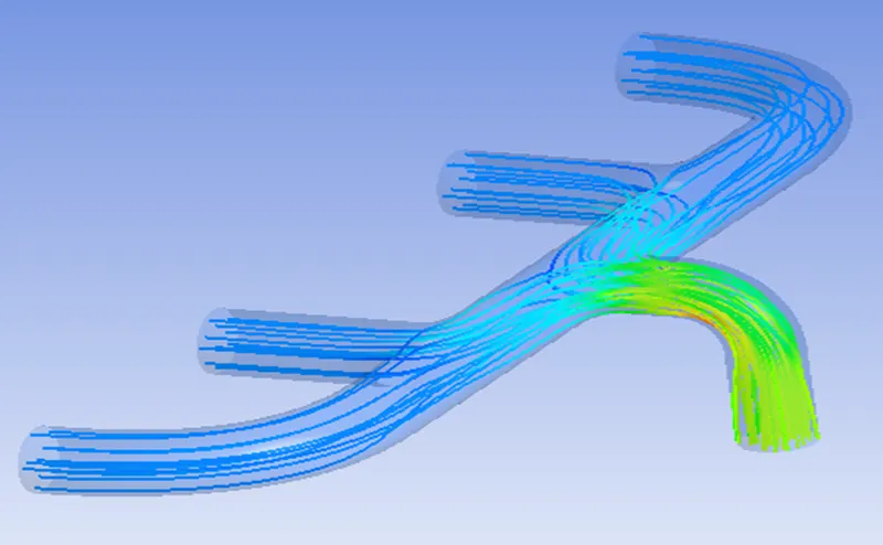
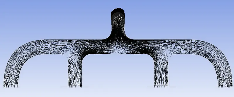
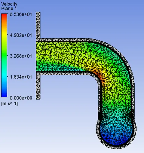
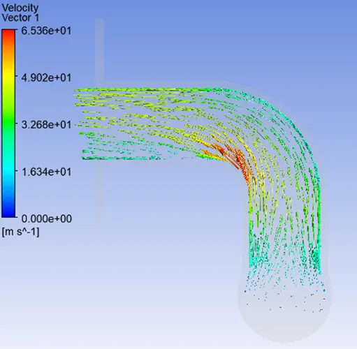
The initial velocity is given as 8 m/sec at all inlets. The max velocity region of the
component is observed to be near the exhaust pipes shown by the red region in the
velocity contour.
Due to the convergence of the exhaust valves into a single exhaust pipe. The velocity
of the exhaust gas multiplies.
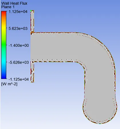
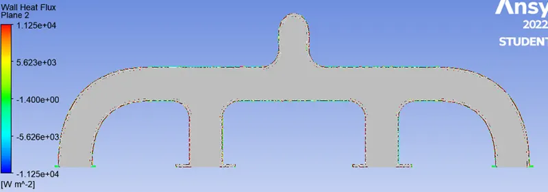
The rate of heat energy movement through a specific surface, per unit surface, is
known as heat flux or thermal flux.
In the Heat Flux Contour, the surface heat flux distribution inside the exhaust
manifold can be seen.
The Surface Heat Transfer Coefficient (K) is the temperature differential between the
solid surface and the surrounding fluid region. It calculates heat transfer
between a fluid and a solid, often through convection or phase change.
The fluid attains the max velocity at the exhaust pipe reaching up to 65.36 m/sec. The
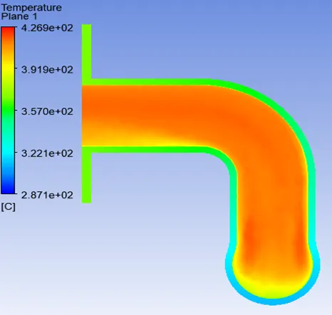
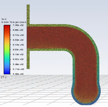
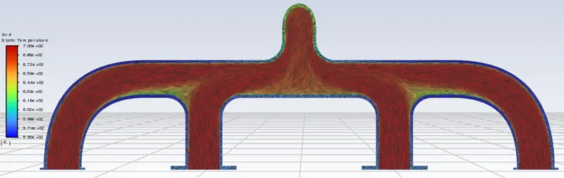
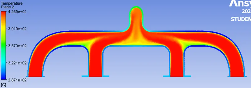
The exit Temperature of exhaust is noted as 426.9 K. Wall Heat Flux attained is 11250
W/m^2.