Week 4 - CHT Analysis on Exhaust port
Aim :- CHT Analysis on Exhaust port
Tools Used :-
1) Space claim
Extract Volume , Share
2) Ansys meshing
Sizing , Inflation , Name selection
3) Ansys fluent
Turbulence model , Boundary condition , Initialization , Compute
4) CFD Post
Contours , Streamline , vector , Plane
Theory :-
CONJUGATE HEAT TRANSFER (CHT)
Conjugate Heat Transfer (CHT) is a type of heat transfer between solid and fuild meduim through the interface between them. This type of heat transfer includes both conduction and convection.
CHT analysis benefits where non-uniform heat transfer occurs and difficult to calculate empirically.
It has application in
1)Electronic cooling
2)Heat exchangers
3)Cooling of gas turbines
4)Combustion chambers and many more
Procedure :-
1) Pre-processing
Geometry
a) Import downloaded Exhaust port geometry in Space-claim
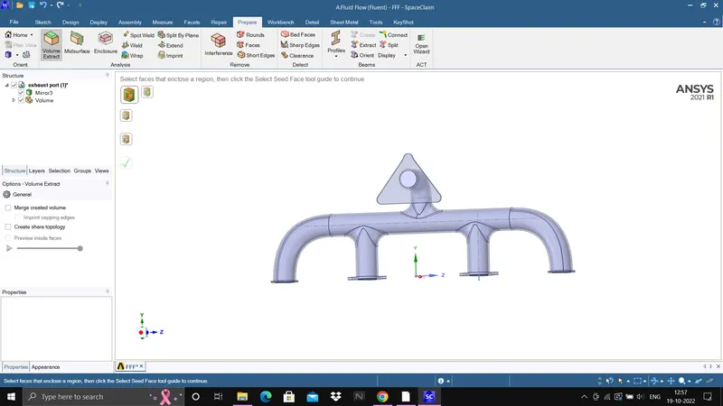
b) Extract the fluid volume using extract volume option
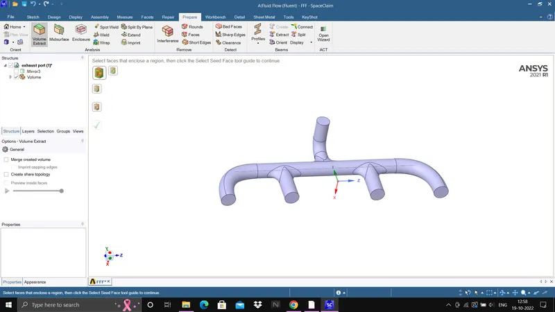
c) Share the topology using share option in worknebch from Space-claim
Meshing
a) Open cleaned geometry in Ansys mesh
b) Create two mesh with given element size
| Cases | Element size | Element numbers |
| Case 1 | 150mm | 262398 |
| Case 2 | 50 mm | 1178895 |
Case 1 :-
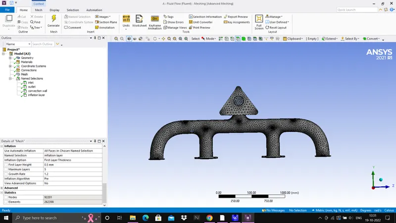
Case 2:- small mesh element size
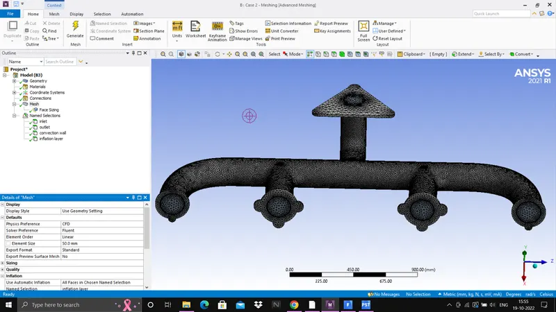
c) Now ,create 5 inflation layer with first layer thickness 0.5 using y+ value 10, in case 2 give inflation mesh size of 10mm
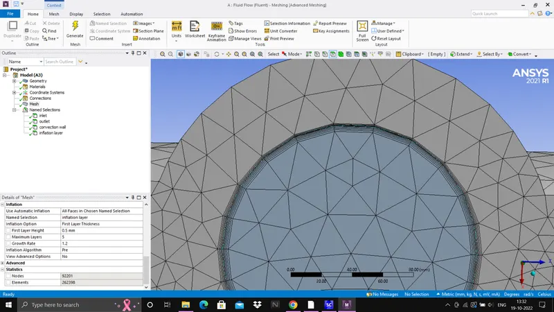
d) Give name to each face as inlet (there are 4 inlets in given geometry) ,outlet , inflation layer (inner surafce) , convection wall (solid surface).
e) Update the mesh i.e., mesh is transferred to solver
2) Solving
a) open the solver which is Ansys fluent
b) As flow is incompressible so select pressure based solver
c) Select the turbulence model which is k-omega SST model in this problem
d) The material will be air
e) Give boundary condition
Inlet -
Velocity inlet - 25m/s
Thermal - 700K
Outlet -
Pressure outlet
Wall convection - 20w/m2.K
f) Create report definition which is Surface heat transfer coefficient.
f) Initialize the simulatiion with hybrid initilization
g) Now compute the problem with 200 iteration
3) Post processing
a) open CFD-Post
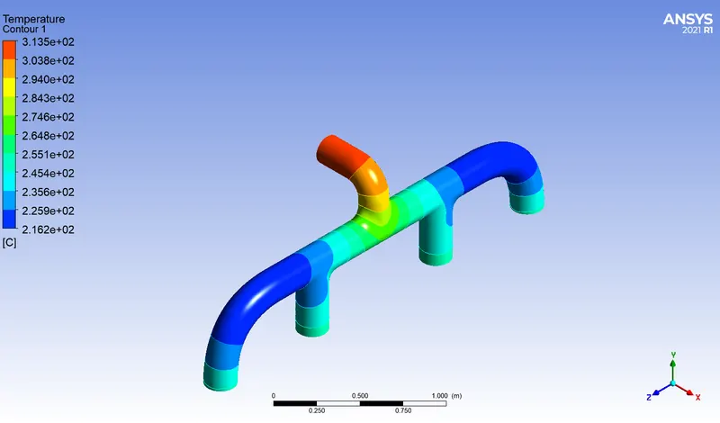
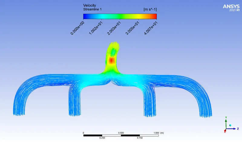
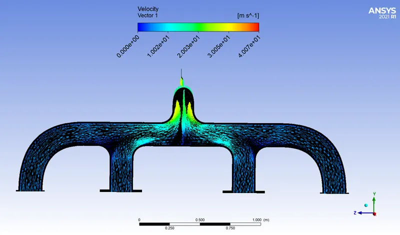
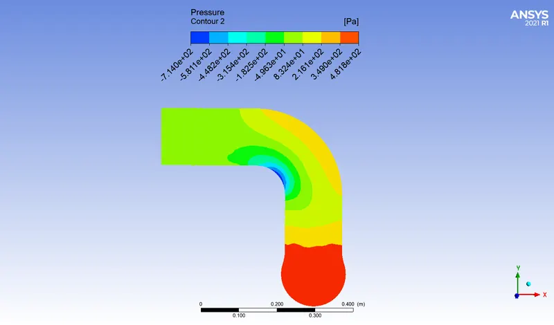
b) Create velocity , temperature , pressure contour , and plot streamline and velocity vector
4) Solve the problem analytically and compare the result with numerical solution
Result :-
Numerical method
| Cases | Element size | Element number | Heat transfer coefficient |
| Case 1 | 150mm | 262398 | 21.3636 w/m2K |
| Case 2 | 50mm | 1178895 | 21.3801 w/m2K |
Analytical method
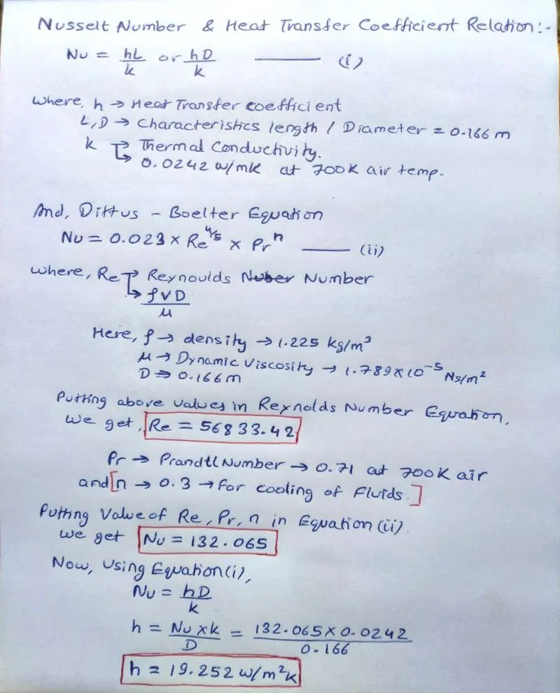
Heat transfer coefficient can be found out by nusselt number relation and Dittus-Boelter equation which is given below.
Reynolds number , Prandtl number ,Types of flow , Conductivity are the factors where accuracy of problem depends.
Validation :-
| Methods | Heat transfer coefficient |
| Numerical method |
Case 1:- 21.36 w/m2K Case 2:- 21.38 w/m2K |
| Analytical method | 19.25 w/m2K |
* On comparison Numerical method result and analytical method result , there is approx 10% error got
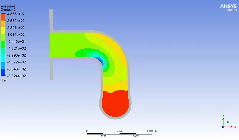
Pressure Contour
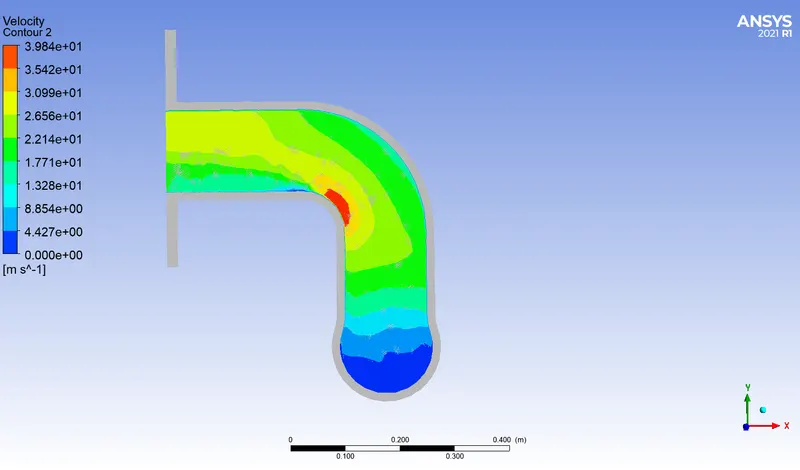
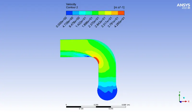
Velocity Contour
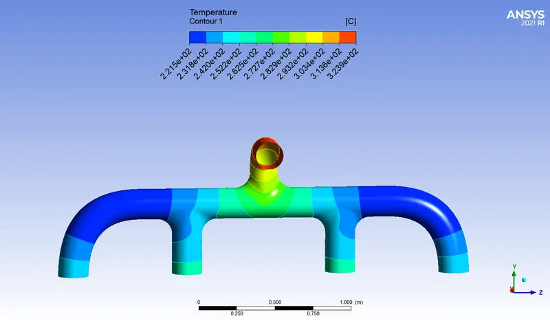
Temperature contour
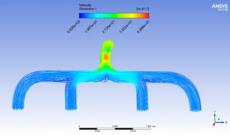
Streamline
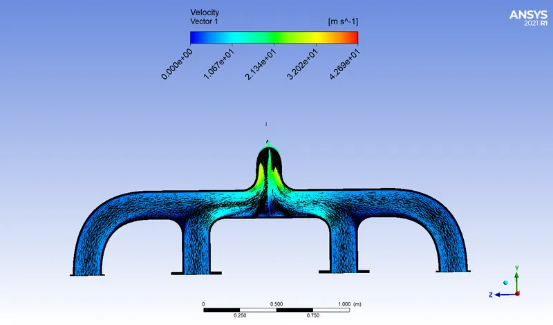
Velocity vector
Case 2
Pressure contour
velocity contour
Temperature contour
streamline
velocity vector
Conclusion :-
CHT analysis of exhaust port has been done with y+ value 10 using k-omega sst turbulence model and heat transfer coefficient is calculated using both numerical and analytical method and it shows that there is 10% change of numerical method result from analytical method result. Velocity , temperature , streamline and velocity vector plot has been obtained showing how heat transfer takes place from liquid to solid medium which is conjugate heat transfer.