Week-4 Challenge WOT Condition Part-2
SOLUTION [1]:
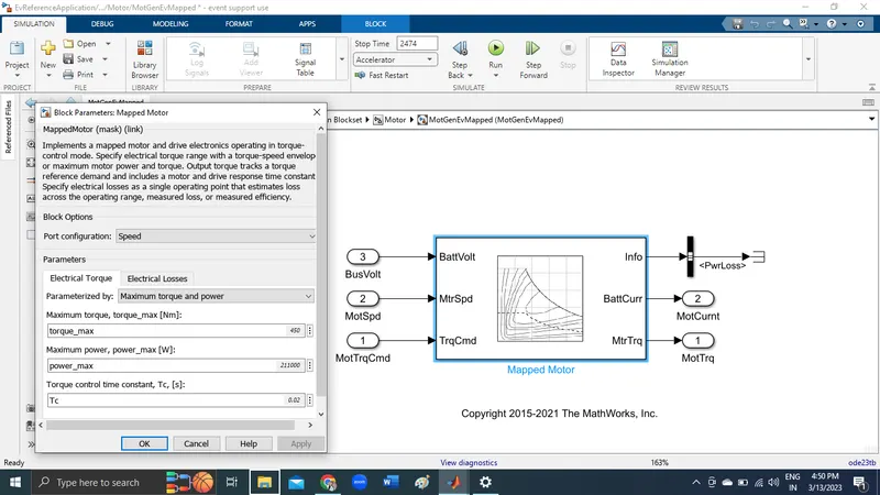
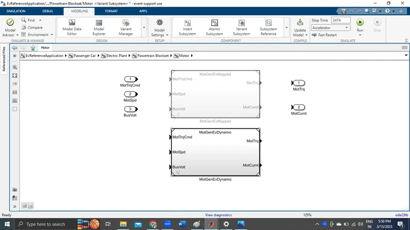
Mapped model :Mapped Models run based on data in the lookup table.
Mapped Motor: We can refer below block parameters of mapped motor, the values are taken from experiments or
old data to implement a mapped motor and drive electronics operating in torque control mode. We have to specify
the electrical torque range with a torque-speed envelope or maximum motor power and torque. Output torque
tracks a torque reference demand and includes a motor and drive response time constant.
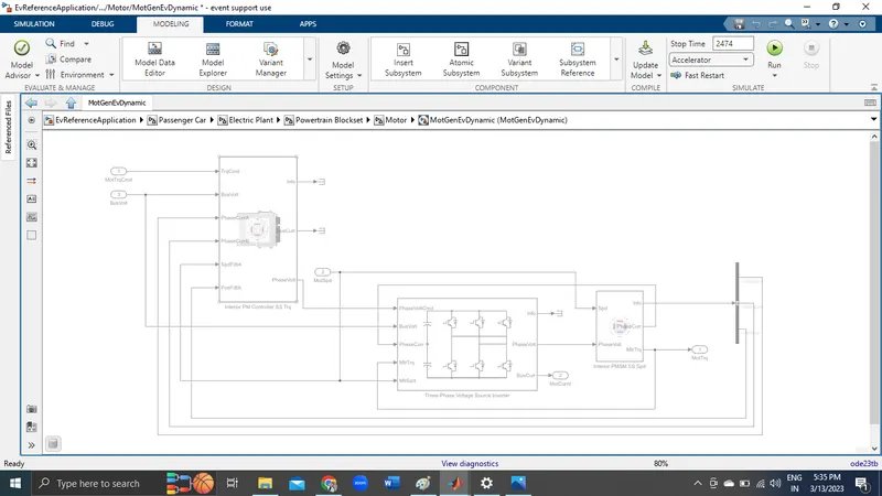
Dynamic model :Dynamic models are used when the internal response to a model with respect to its components
is needed. Basically this represent the actual component.
This model has motor components such as inverter, phase controller, PSMS & feedback circuits.
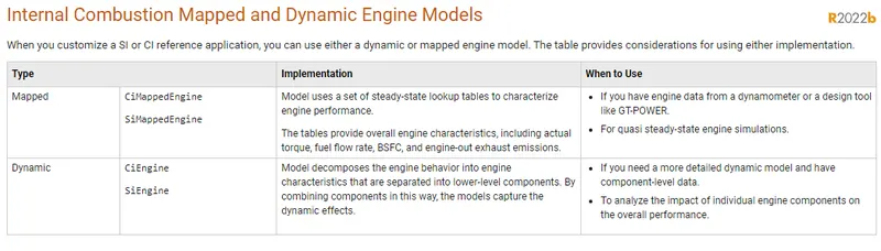
The difference between mapped and dynamic model of engine is tabulated below in screenshot
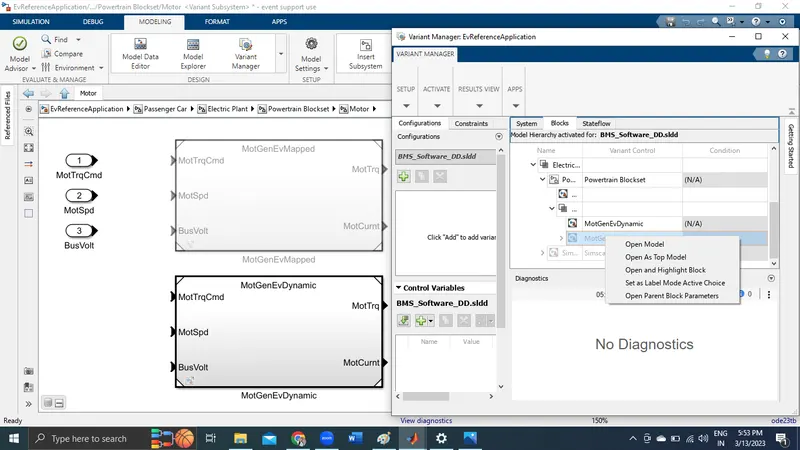
Model Type Can be Changed by following below Steps.
Select the Model which you want to configure -> Choose Variant Manager -> Right Click the Model you wish to
choose and then Set as Label Mode Active Choice.
SOLUTION [2]:
Model calculate miles per gallon is shown below
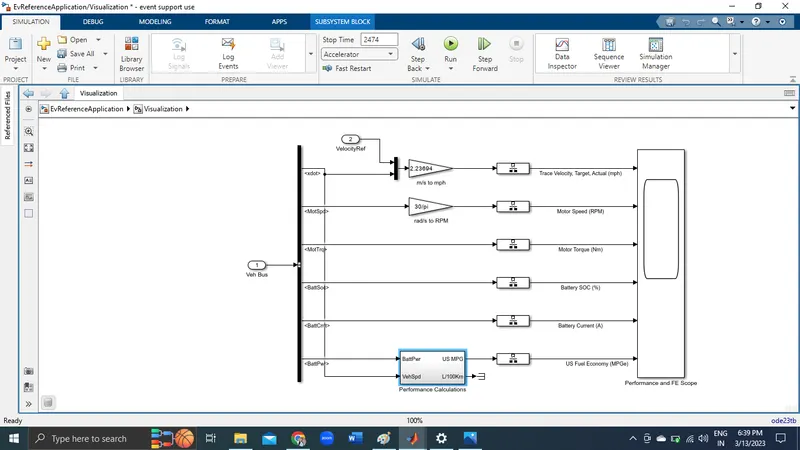
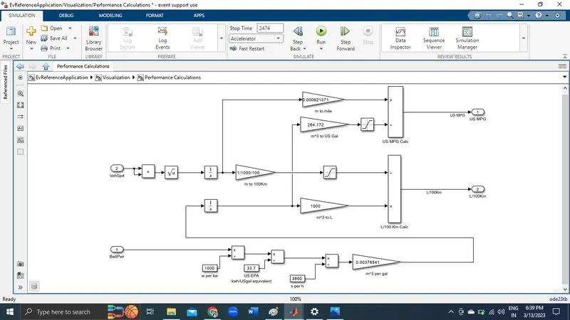
Vehicle Speed data is used to calculate the distance traveled in meters which is then converted to miles
Step 1:Battery power data is used to find power used in kWh which is then converted to gasoline-equivalent using
US EPA value by dividing with 33.7
Step 2: As per the US environmental protection agency(EPA) 1 gallon of gasoline is equal to 33.7 kWh
Step 3:Dividing distance traveled in miles by the number of gallons, we can get miles per gallon.
Step 4:For HEV , gallon(gasoline-equivalent of battery power) is added with gallon used by IC engine then miles
per gallon is calculated.
These Factors are considered to model fuel flow
1-Vehicle Speed
2-Battery power
SOLUTION [3]:
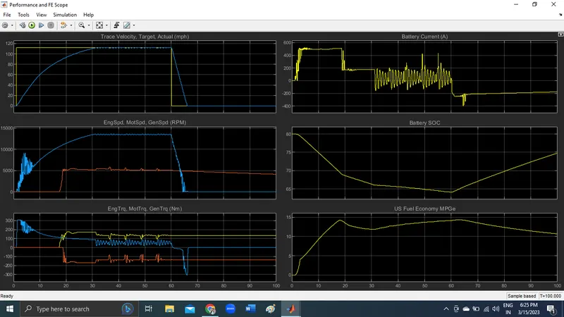
HEVMmReferenceApplication with FTP75
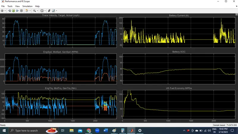
WITH NO GRADE AND WIND VELOCITY WOT
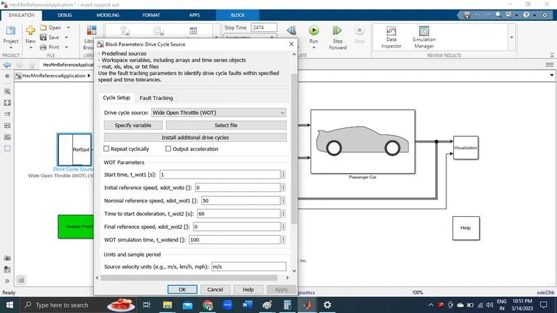
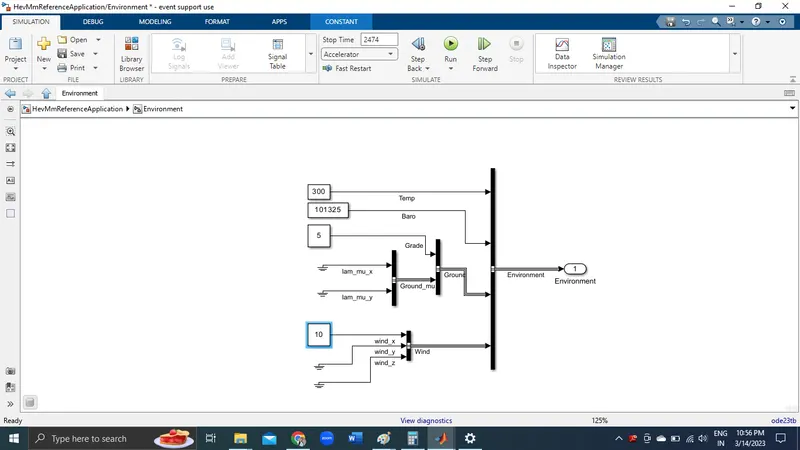
At grade=5 wind value is 10
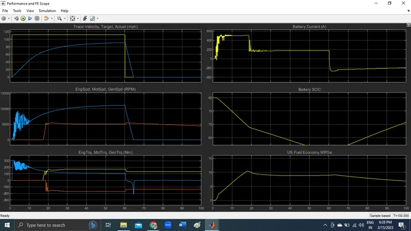
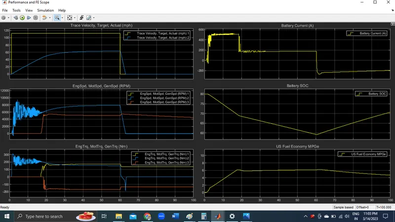
At grade=10 wind value is 20
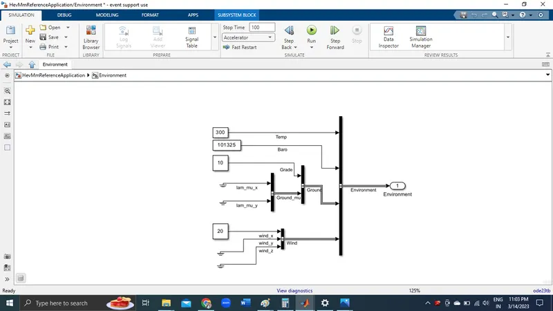
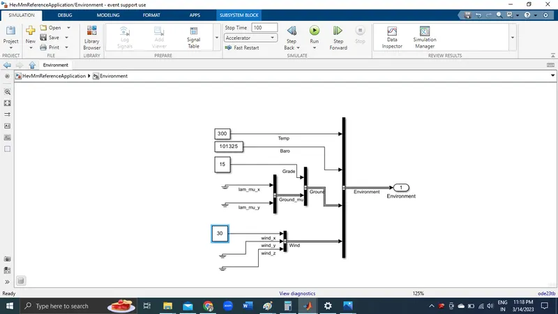
At grade=15 wind value is 30
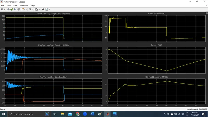
Hence we can conclude that the vehicle with lower degree grade and lower wind velocity,
Can reach high speed in short amount of time.
Have high fuel efficiency.
Have high deceleration time.
Have better SOC.
SOLUTION [4]:Keeping all other parameters same, the simulated results of hybrid Shown above and pure electric powertrains shown below.
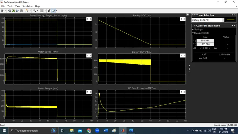
Simulation of pure electric vehicle with WOT drive cycle
Simulation of Pure EV with WOT condition without any change
The drive cycle source window parameters are kept similar to the HEV simulation.
The simulation is made to run with no change in the environment block.
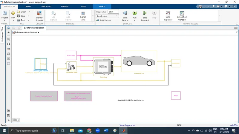
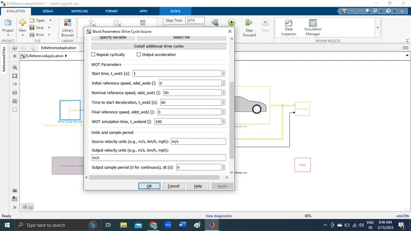
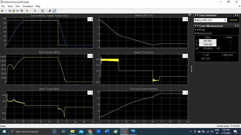
The result of the simulation
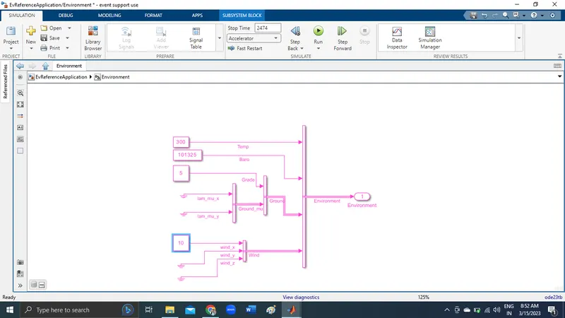
Simuation of Pure EV with WOT condition with changes in environment block
The drive cycle source window parameters are kept similar to the HEV simulation.
The Grade value is set to 5 degrees
The wind velocity is set to 10 m/s in x axis direction
Other parameters remains unchanged
The simulation is made to run with the above changes
The result of the simulation
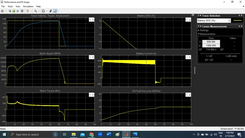
Simulation of Pure EV with WOT condition with changes in environment block
The drive cycle source window parameters are kept similar to the HEV simulation.
The Grade value is set to 10 degrees
The wind velocity is set to 20 m/s in x axis direction
Other parameters remains unchanged and stop time taken 100 s
The simulation is made to run with the above changes
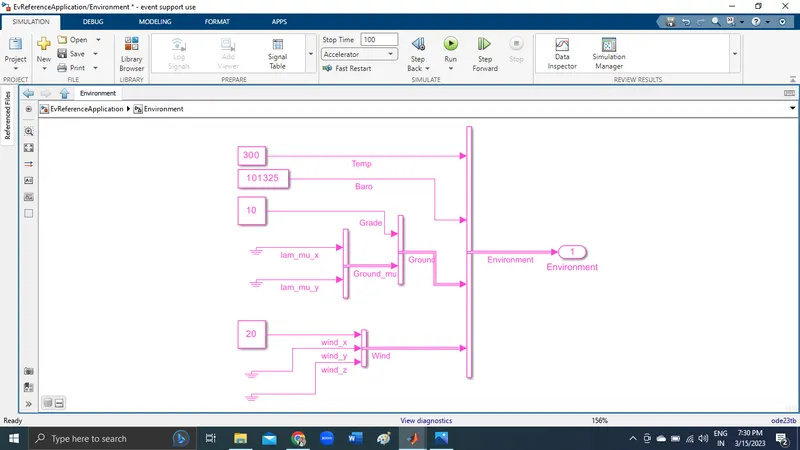
The result of the simulation
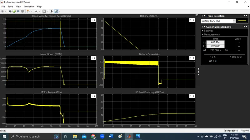
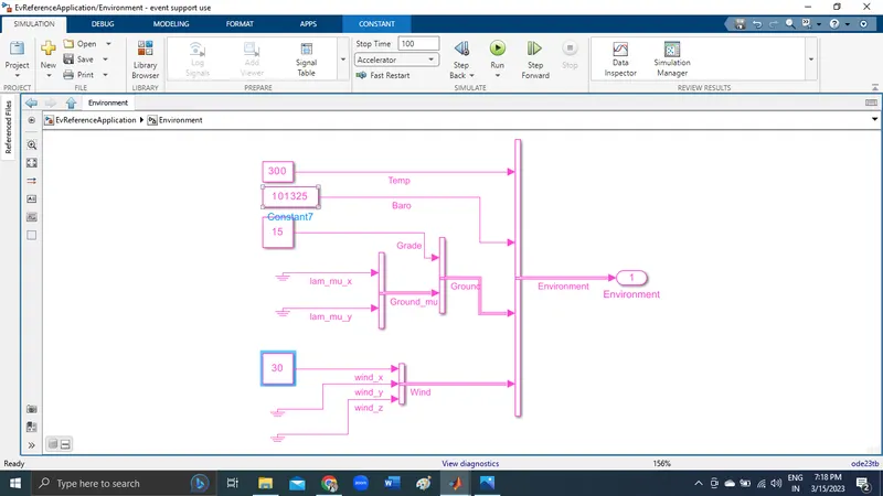
The result of the simulation
Can reach high speed in short amount of time.
Have high fuel efficiency.
Have high deceleration time.
Due to high deceleration time, the recharging time of battery is also high
Therefore better SOC
Hence All the above task performed.