Week 4 Challenge : CFD Meshing for BMW car
1] AIM -
To generate volumetric mesh for BMW car for CFD applications.
2] OBJECTIVE -
- To create half model of the given geometry and solve all geometrical errors.
- To perform topology cleanup,generate PID's and generate surface mesh.
- To create wind tunnel. To generate volumetric mesh from the surface mesh and do symmetry.
3] METHODOLOGY -
3.1] Topology Cleanup -
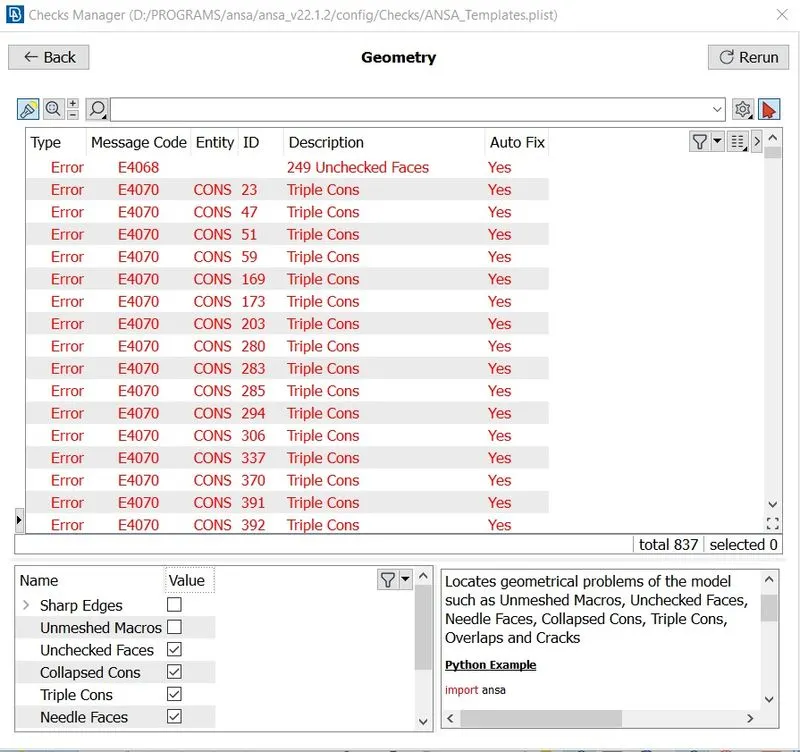
As we open our model in ANSA,first we will perform checks on the geometry to see all the errors that are present in the model .Beside script tool there is arrow botton,click on it and select ckecks and select geommetry.Then from the bottom part of the window we will select the things which we wants to check then click execute.We can see many errors listed.Lets resolve them.
First we will topo tool.Topo is opposite of release.Release will create 2 single cons from a double con and 3 single cons from a
triple con.Topo will do the same in opposite manner i.e. from 3 surfaces it will create triple con and from 2 surfaces will create
double cons.Topo is useful when, we see triple cons but there are no overlapped surface then we can release and do topo again just to show that there aren't any triple cons present or any overlapped surfaces present.
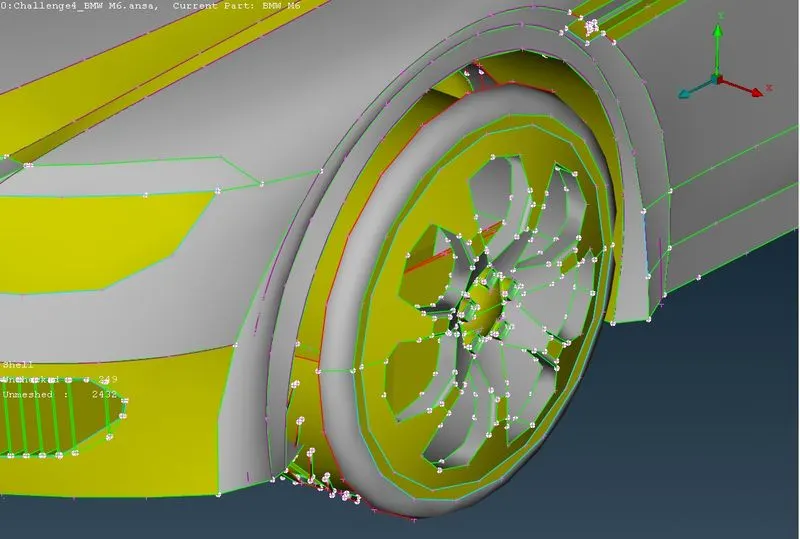
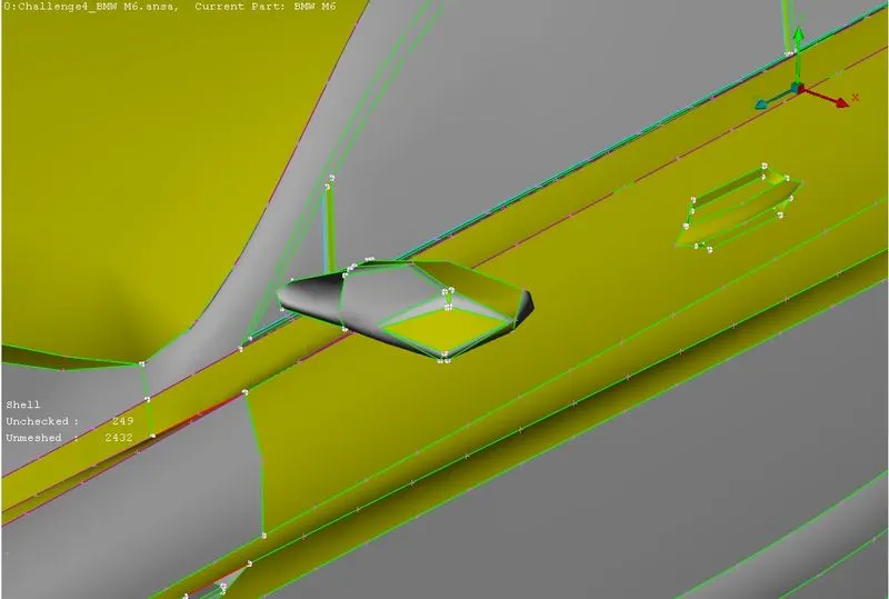
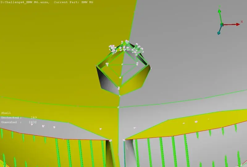
Not many features are captured appropriatly,as can be seen at edges around various commponents,i.e. our cons resolution in bad. There are many ways to increase cons resolution,like manually resolving each component or we can use perimeter option from mesh deck.
In Mesh deck => In perimeters => Length => Select whole model => Enter length 1 mm.
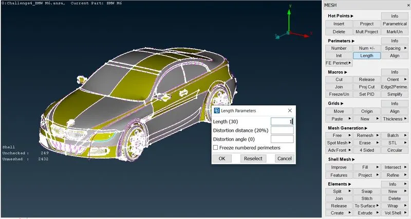
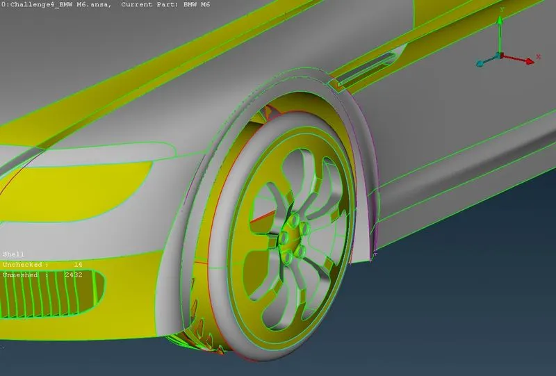
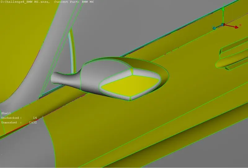
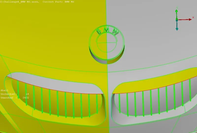
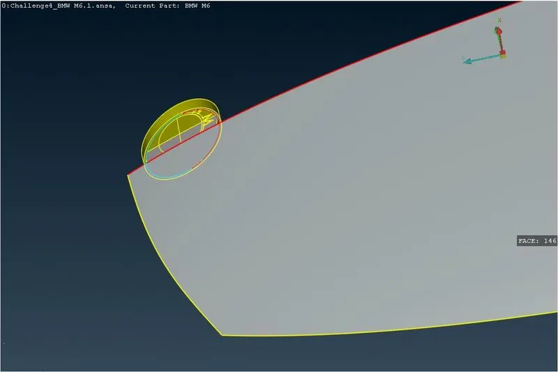
This will reduce the distance between two nodes,which evident from much improved cons resolution.As model is symmetric we will only use half of it ,will work on it,do topo cleanup, do mesh,then reflect half side on other side.Delete half car model using universal delete,except car logo as it's not symmetric.
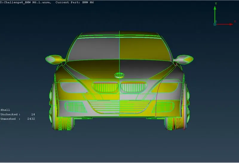
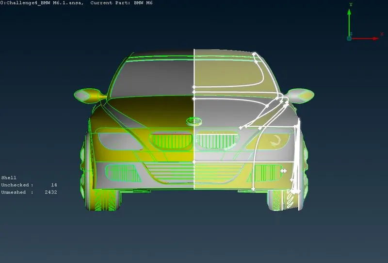
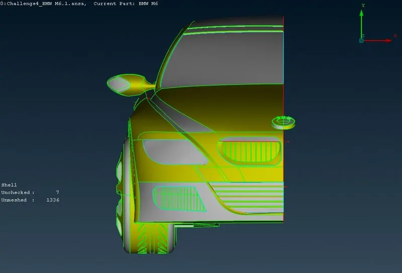
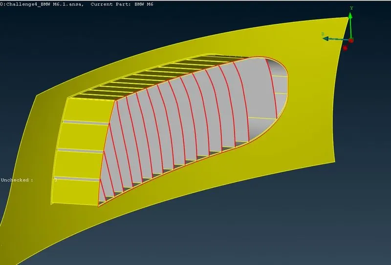
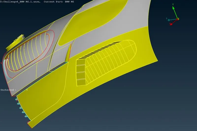
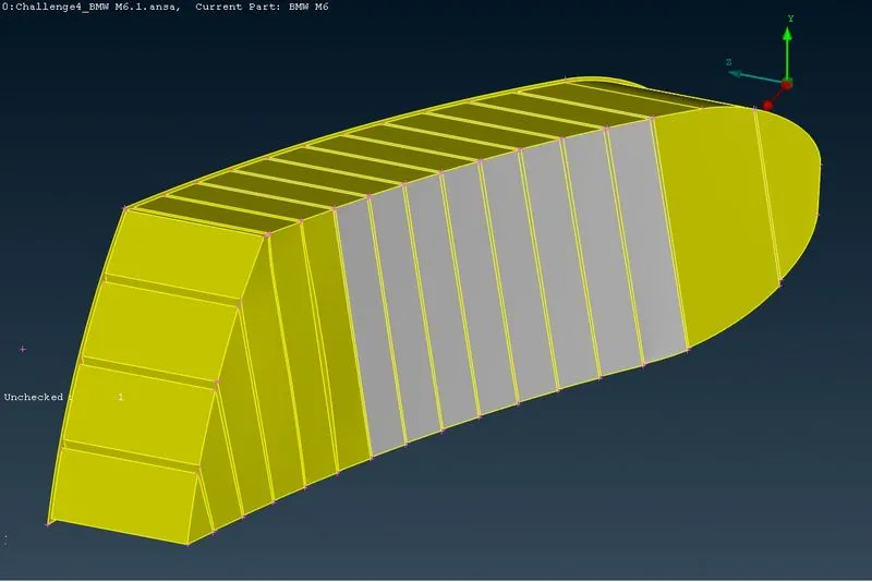
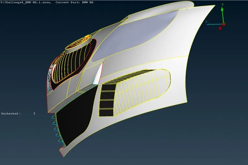
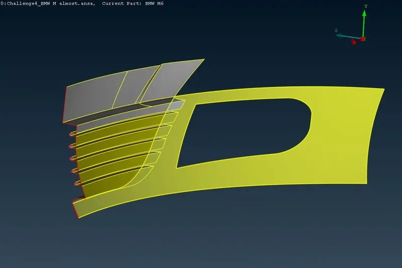
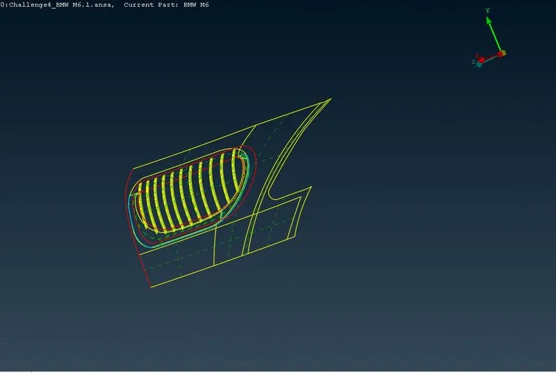
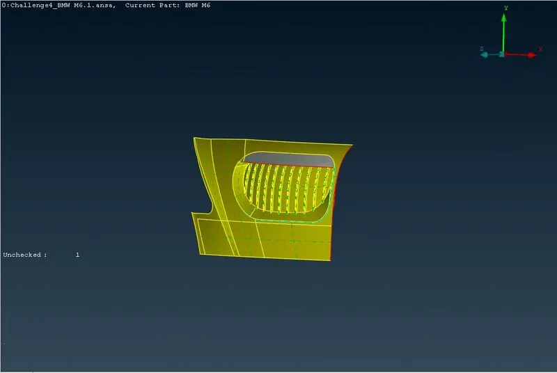
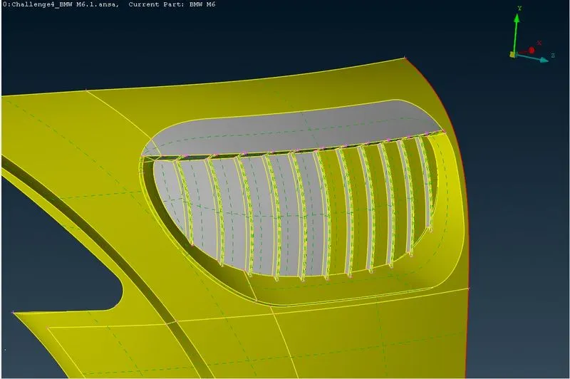
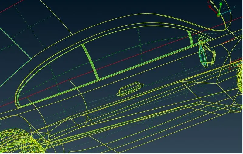
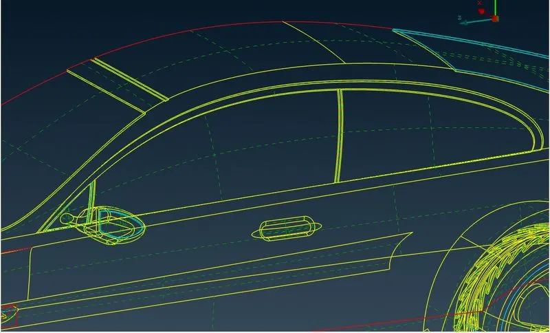
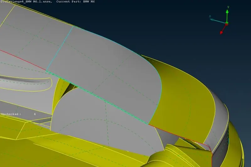
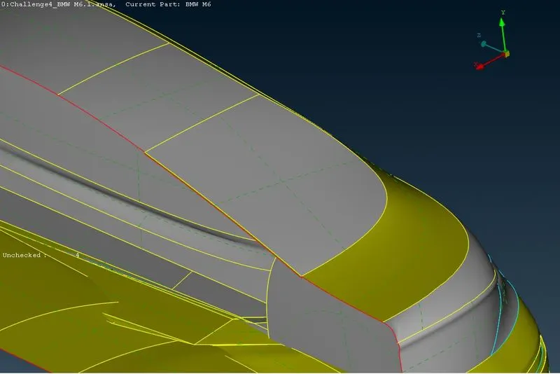
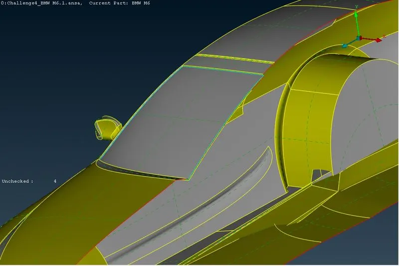
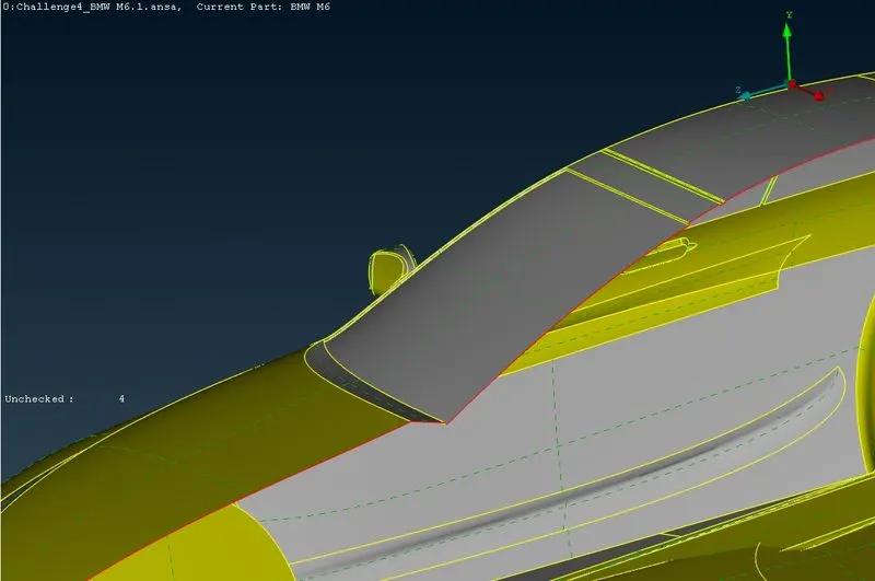
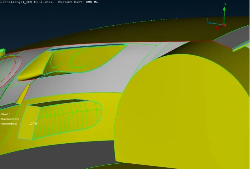
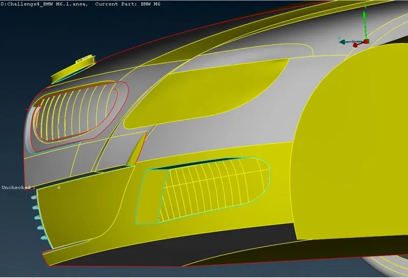
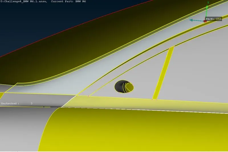
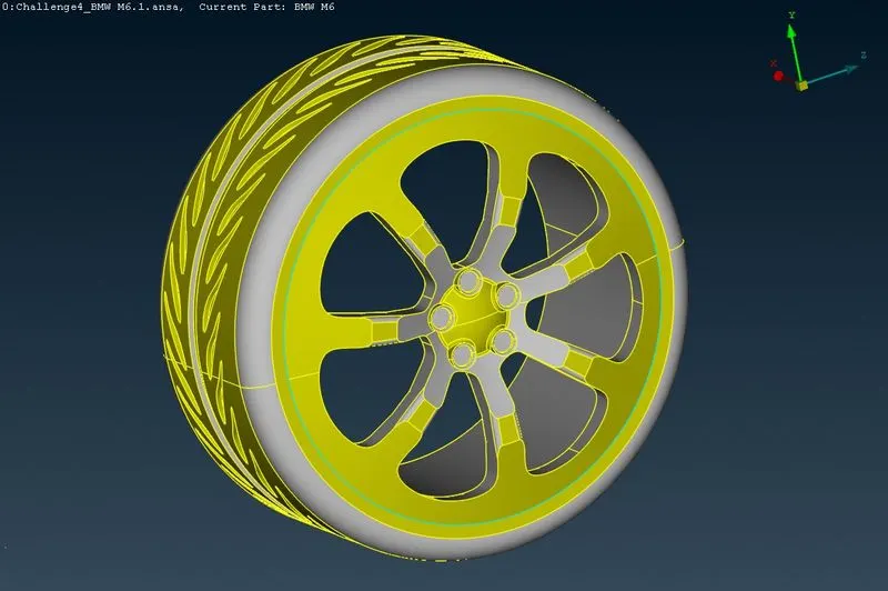
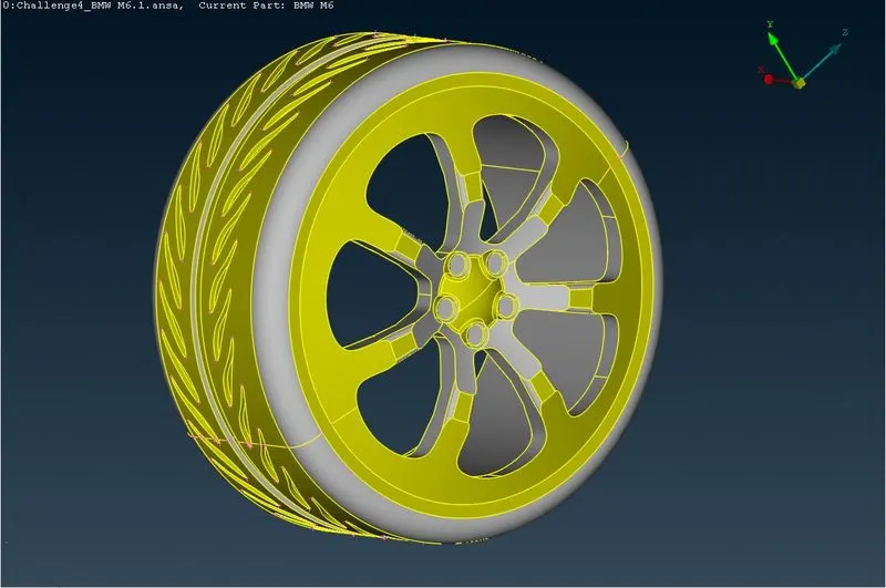
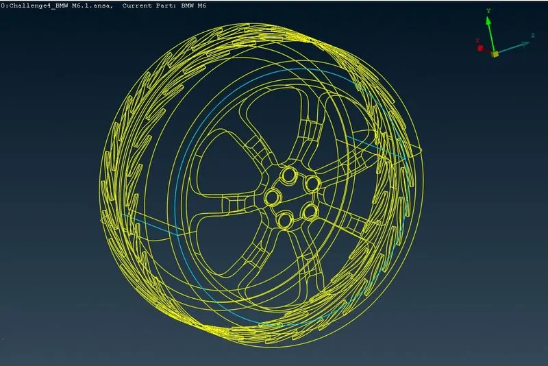
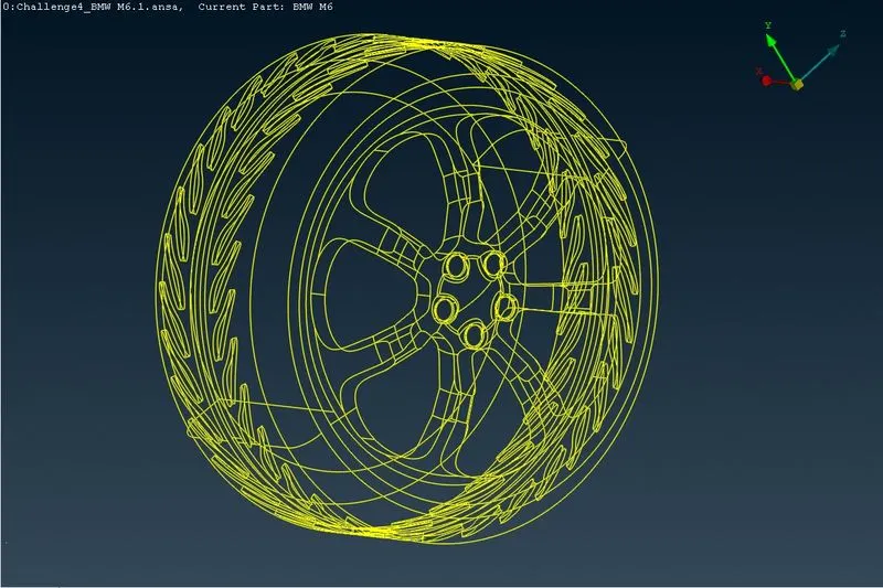
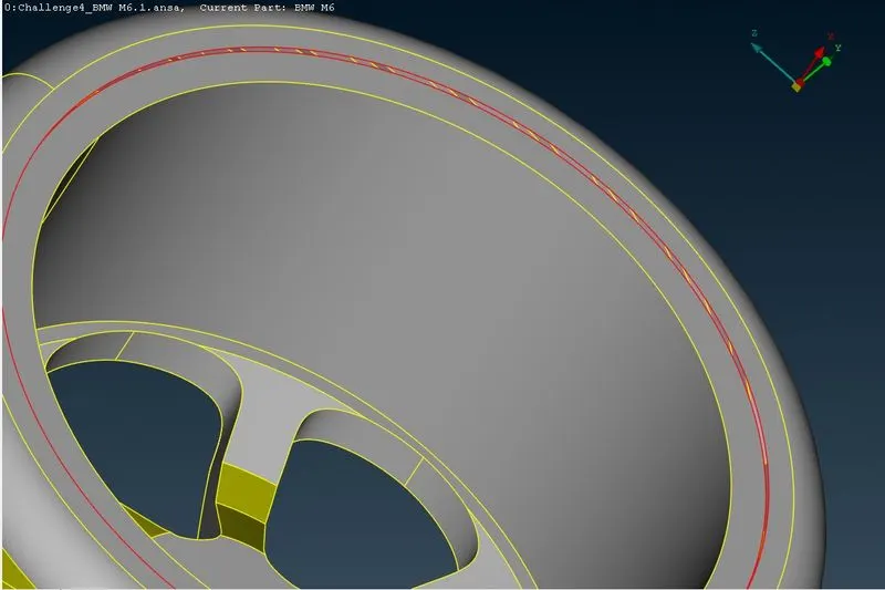
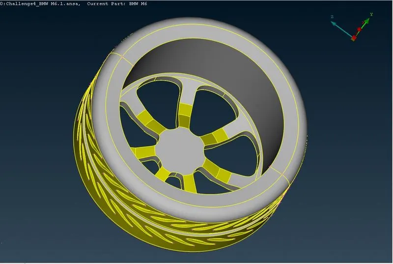
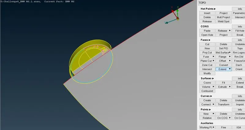
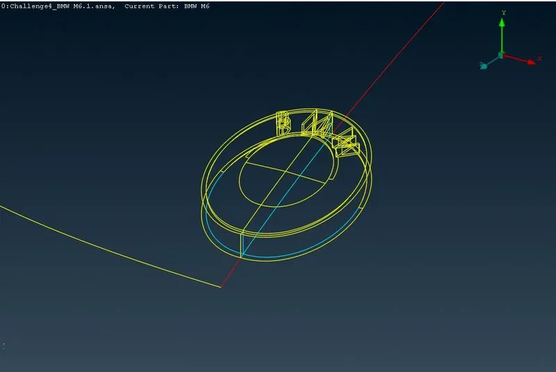
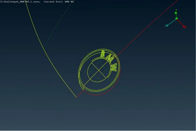
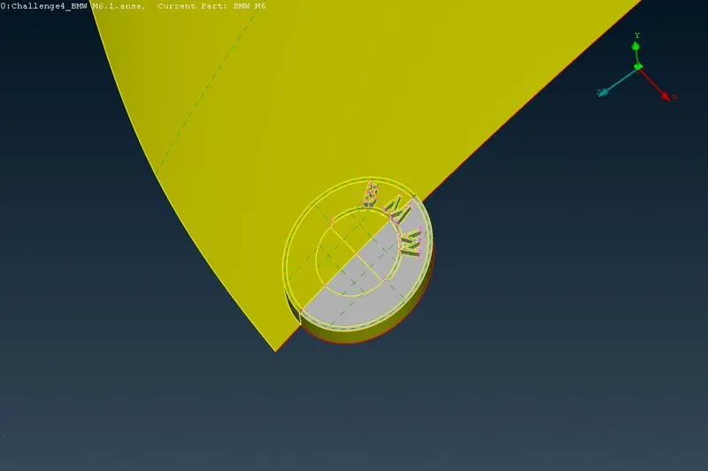
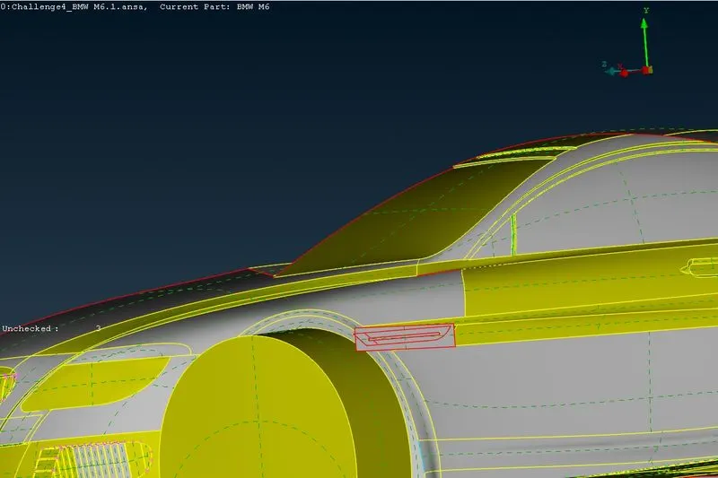
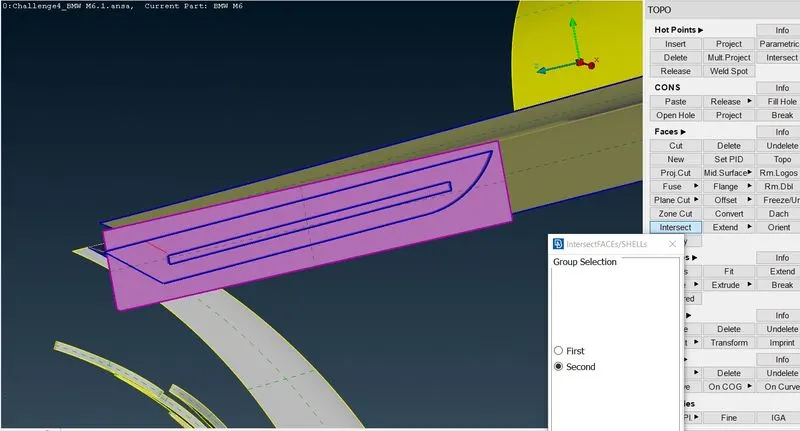
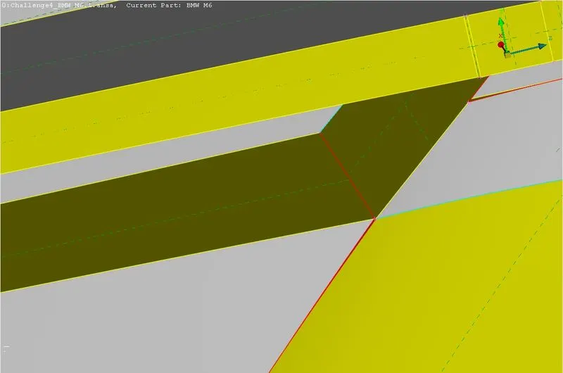
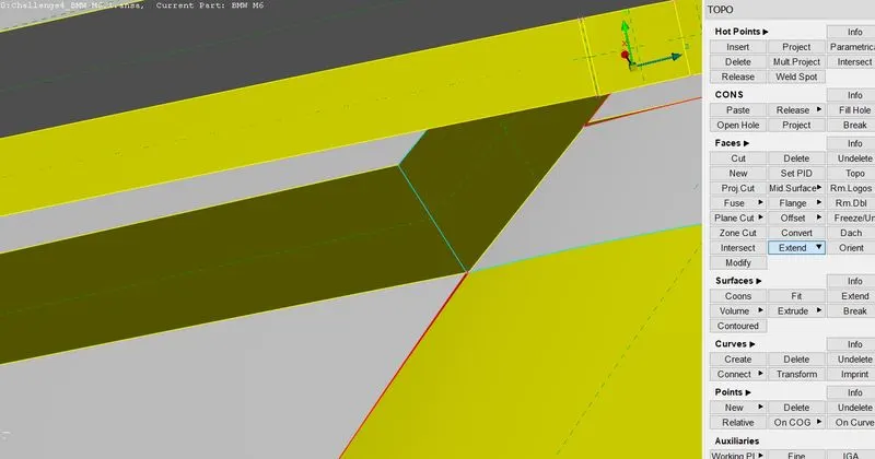
Now will delete all unnecessary surfaces from inside the car model,as we are concerned about outside of the car and area between car outer surface and wind tunnel.Any extra surfaces will create unnecessary volumes utilising memory and time.As shown in the below pictures will perform topology cleanup on our model and will try not to have any single or triple cons except,at locations around which symmetry will be performed.Will remove any extra hot points.Also will use CUT tool to create cons whereever necessary.Also delete any overlapped surfaces.Overlapped surfaces may cause an error while going in the volumetric mesh.Once we go in the volumetric mesh ,we may get generation error,that error is basically showing us overlapped surfaces.
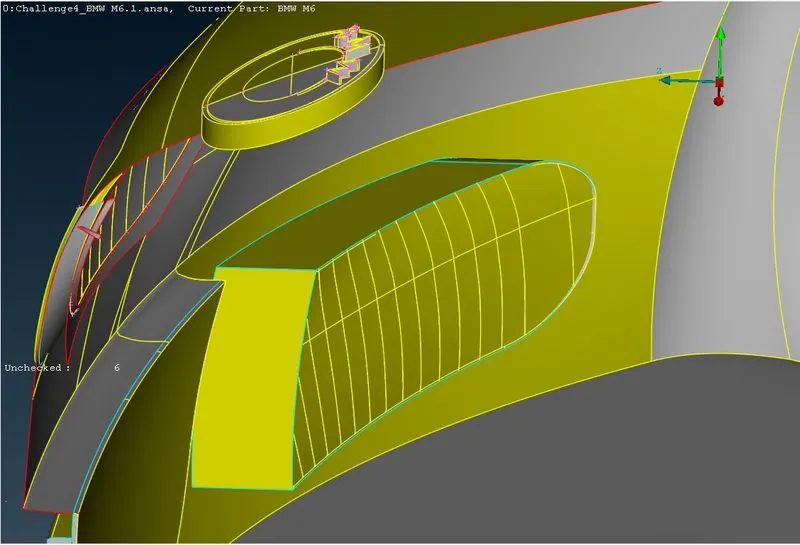
3.1.1] Side Grill -
3.1.2] Middle Grill -
3.1.3] Front Upper Grill -
3.1.4] Windows -
3.1.5] Front Lights -
3.1.6] Rear Lights -
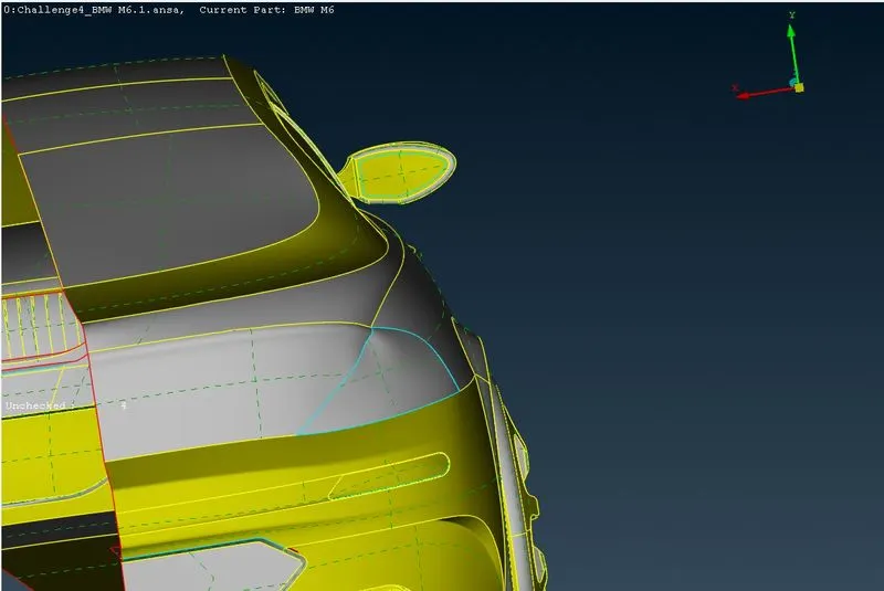
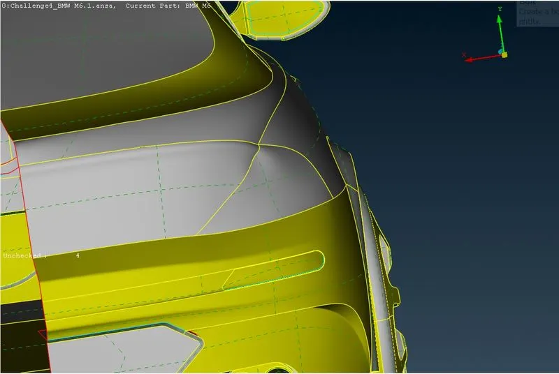
3.1.7] Rear view mirror -
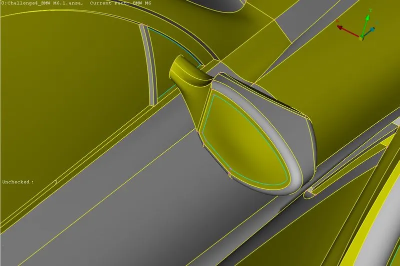
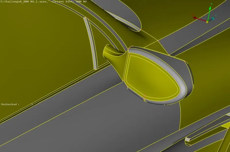
3.1.8] Tyres -
4.1.9] Logo -
3.1.10] Side Aero Fairing -
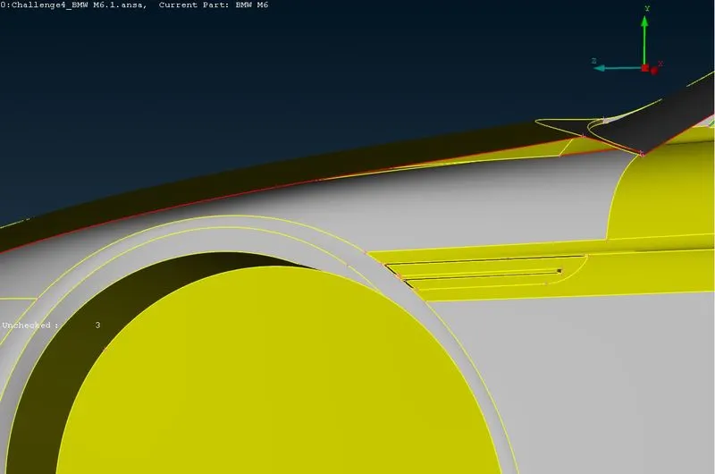
3.1.11] Rear Bumper -
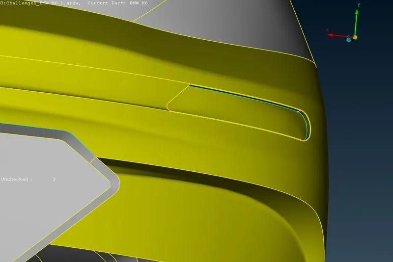
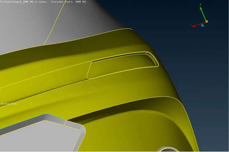
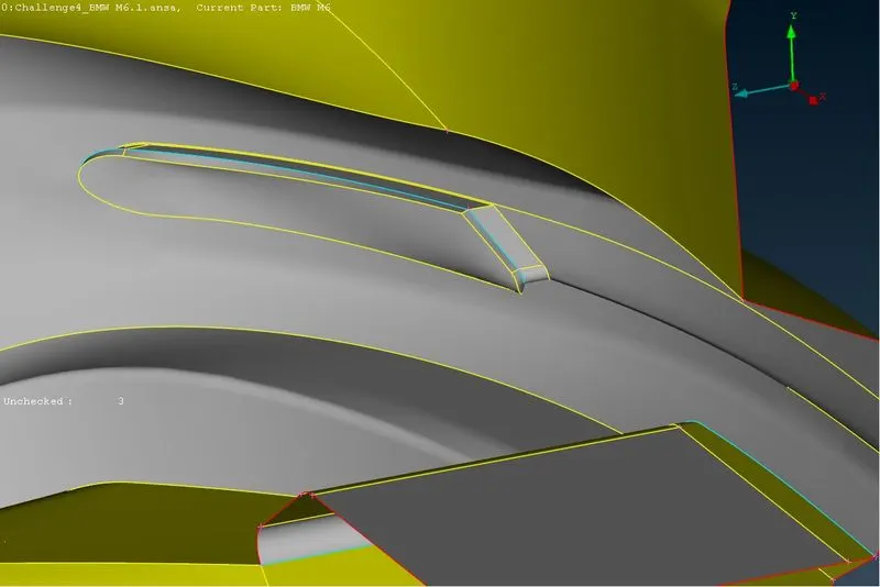
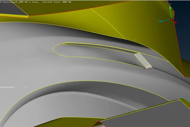
3.1.12] Other Components -
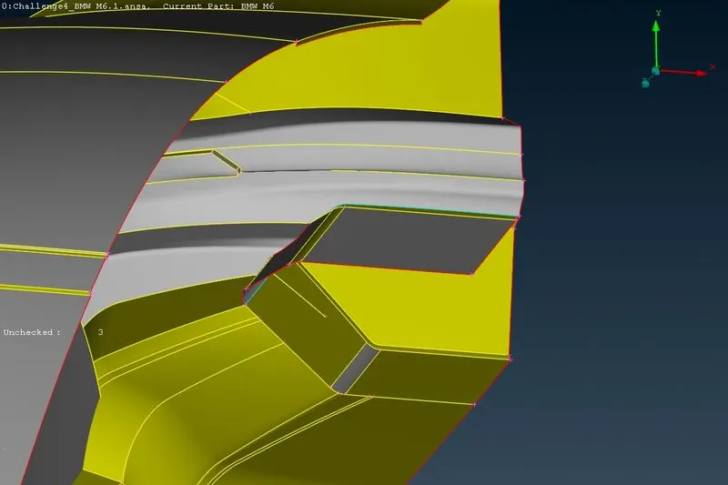
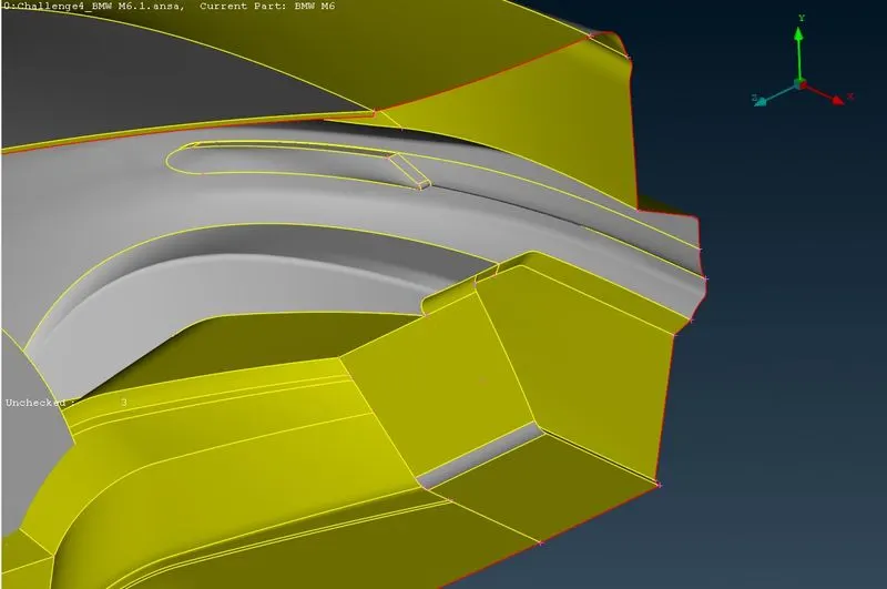
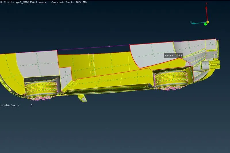
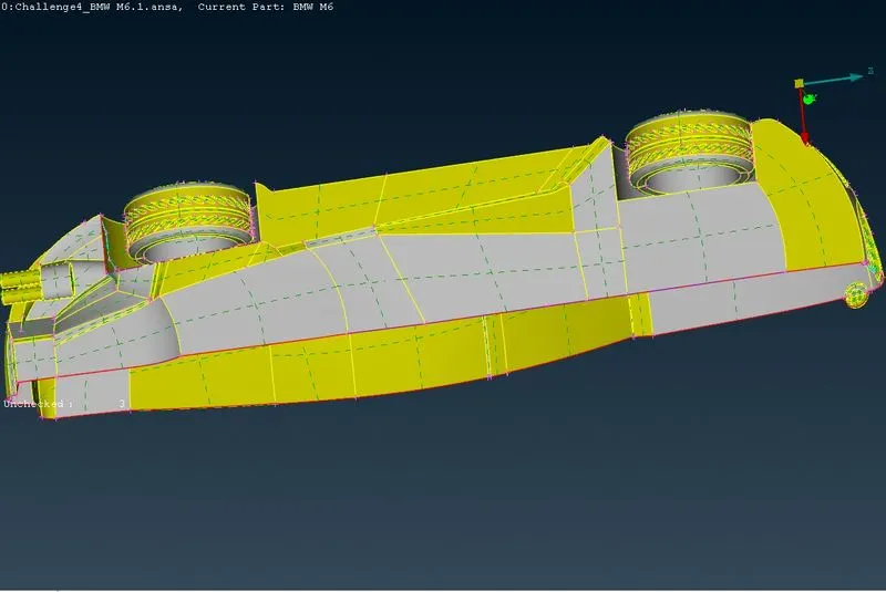
3.1.13] Final Geometry After Topo Cleanup -
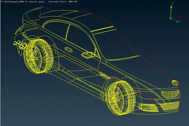
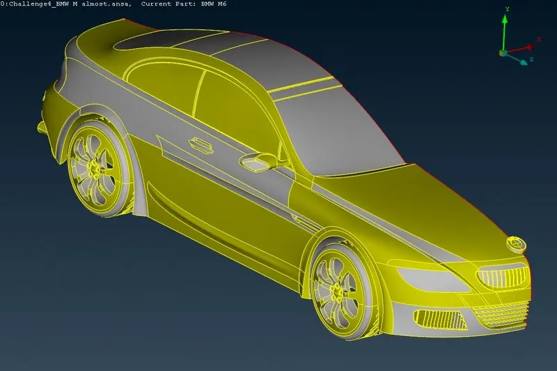
4.1.14] Final Checks After Topo Cleanup -
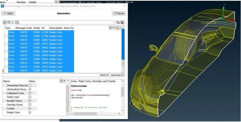
From the above image we can see that, only single cons are left which will be use in creating symmetric other side.
3.2] PID Creation -
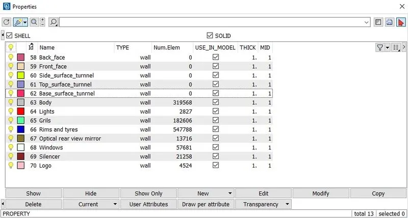
Now lets create PID's which will come handy during meshing.To do that follow below procedure ,
Click Properties => right click and select New => select PSHELL => again select PSHELL => Give name as Silencer => ok.
Simillarly create body,lights,window,grills,rims and tyres,optical rear view mirror and logo PID's.
Now ,to assign each PID to it's respective part follow below steps,
Right click on PID name => Apply => select the respective part => click middle mouse button to confirm.
Simillarly assign all the PIDs.
3.3] Meshing -
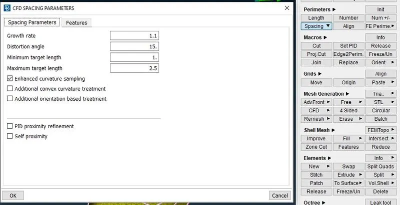
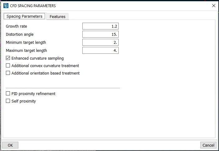
Now here we need to create mesh for various PID's by using below data,
Target Lengths -
Body - 3 mm
Lights - 4 mm
Grills - 1 mm
Rims and Tyres - 2 mm
Optical Rear View Mirror - 2 mm
Window - 2 mm
Silencer - 3 mm
Logo - 1 mm
3.3.1] Optical Rear View Mirror -
a) Target Length Criteria
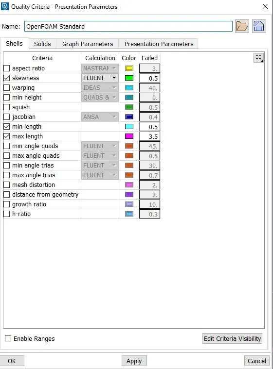
b) Quality Criteria
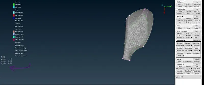
c) Before Using Smooth option( in Shell Mesh module)
d)Off Elements using Smooth options ( in Shell Mesh module)
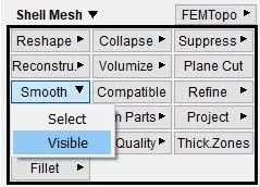
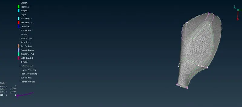
e)Off Elements using Re-construct options ( in Shell Mesh module)
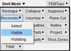
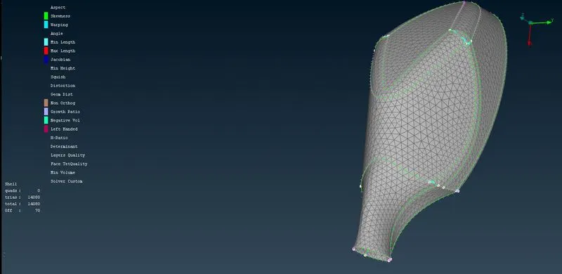
f) AFter recontructs and adjusting the elements with Zero Off Elements
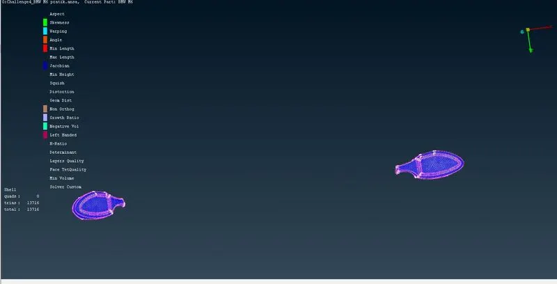
Similarly Repeating all the above steps for others PIDs, We Get
3.3.2] Windows -
a) Target Length Criteria
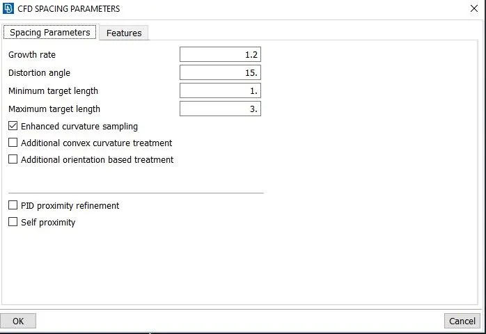
b) Quality Criteria
c) Before Using Smooth option( in Shell Mesh module)
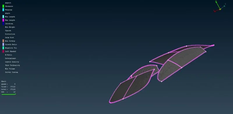
d)Off Elements using Re-construct options ( in Shell Mesh module)
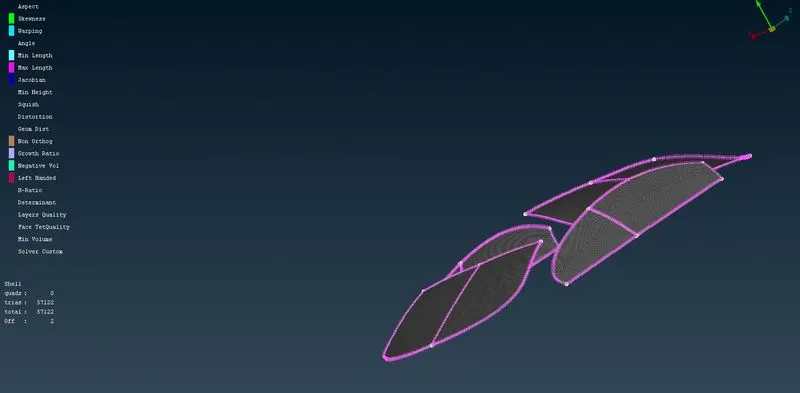
e) AFter recontructs and adjusting the elements with Zero Off Elements
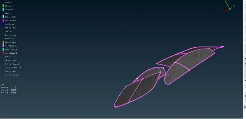
4.3.1] Logo -
a) Target Length Criteria
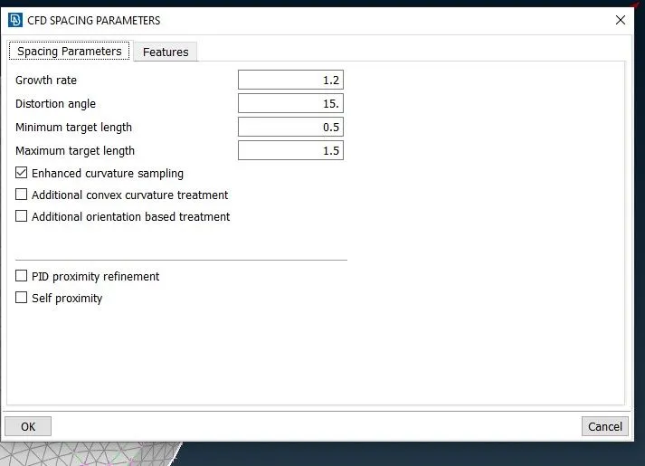
b) Quality Criteria
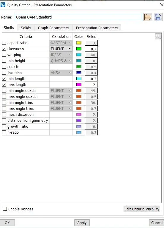
d)Off Elements using Re-construct options ( in Shell Mesh module)
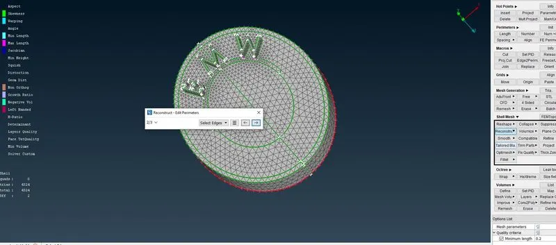
D) AFter recontructs and adjusting the elements with Zero Off Elements
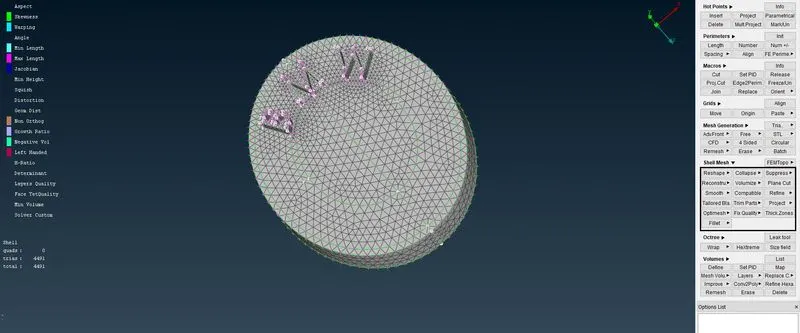
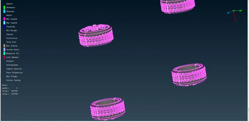
3.3.4] Rims and Tyres -
a) Target Length Criteria
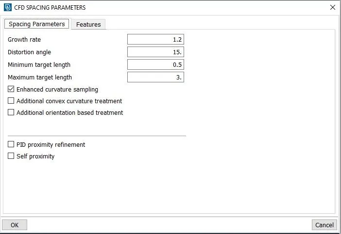
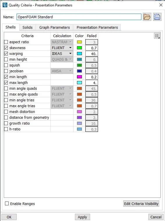
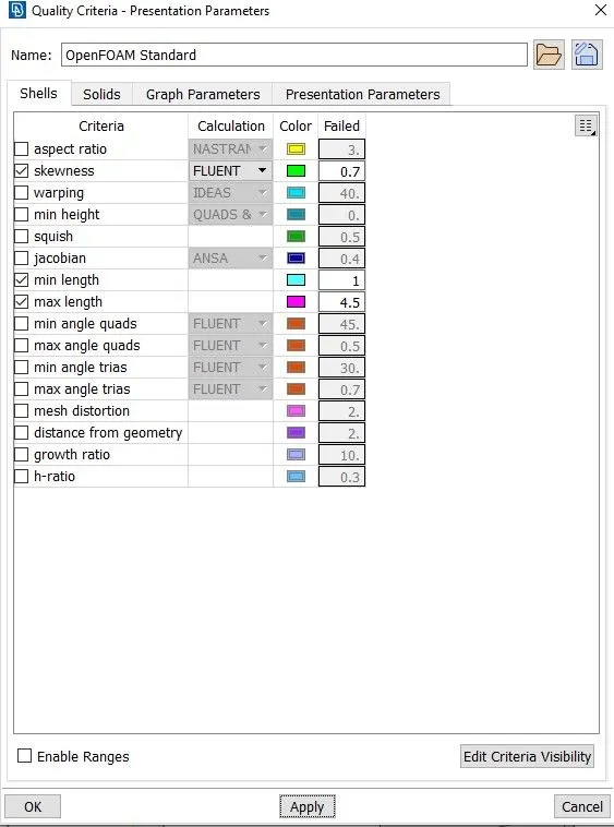
b) Quality Criteria
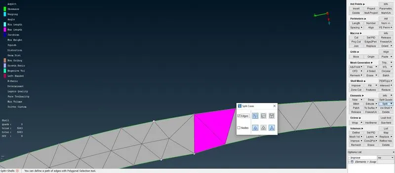
c) Using SPLIT Option to break large length element into 2 or more small elements
d)Off Elements using SMOOTH options ( in Shell Mesh module)
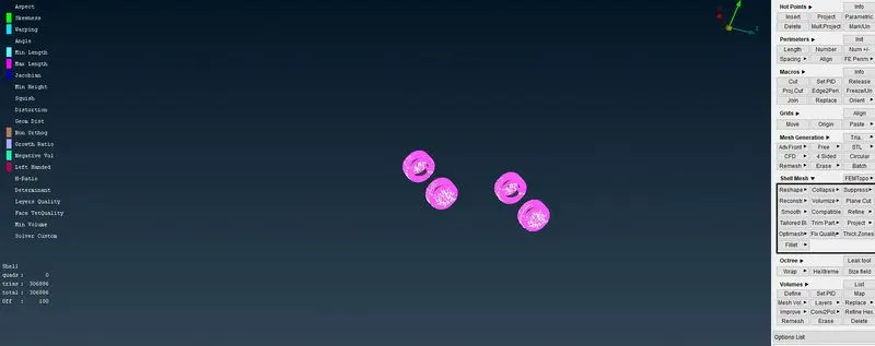
e) AFter recontructs and adjusting the elements with Zero Off Elements
3.3.5] Silencer -
a) Target Length Criteria
b) Quality Criteria
c) Before Using Smooth option( in Shell Mesh module)
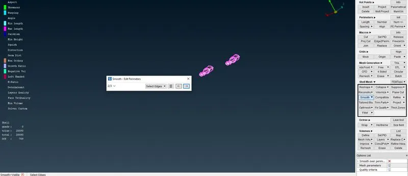
d)Off Elements using Re-construct options ( in Shell Mesh module)
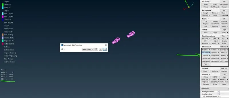
e) AFter recontructs and adjusting the elements with Zero Off Elements
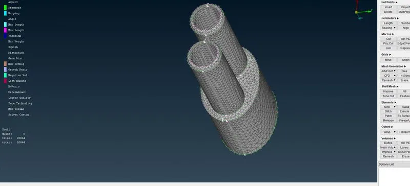
3.3.6] Body -
a) Target Length Criteria
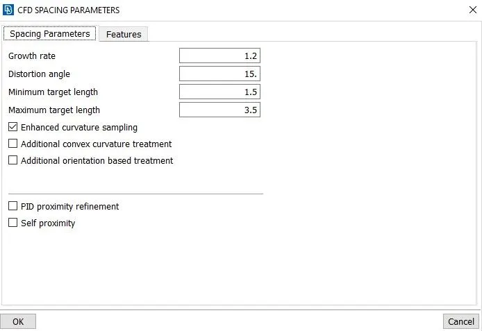
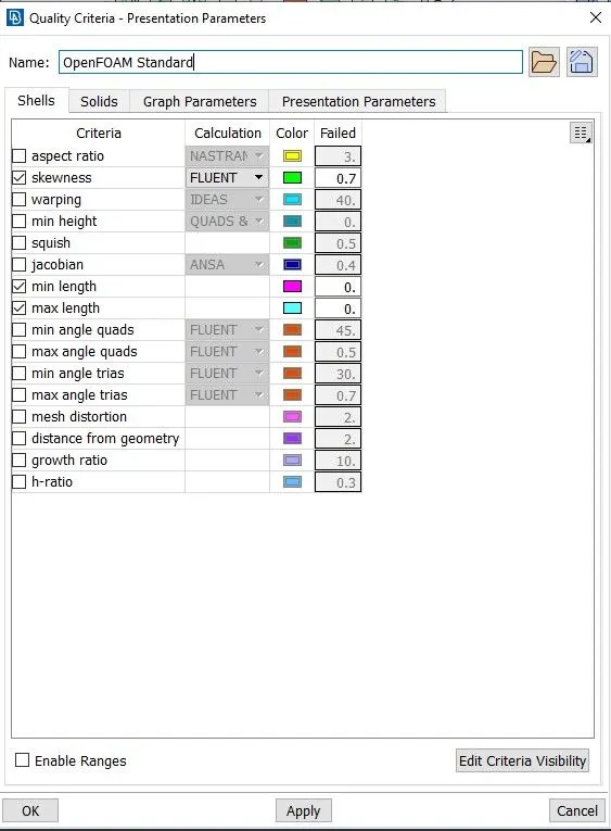
b) Quality Criteria
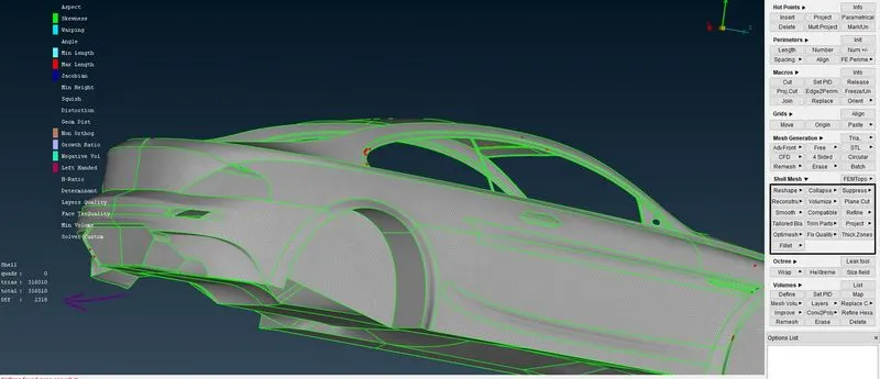
c) Before Using Smooth option( in Shell Mesh module)
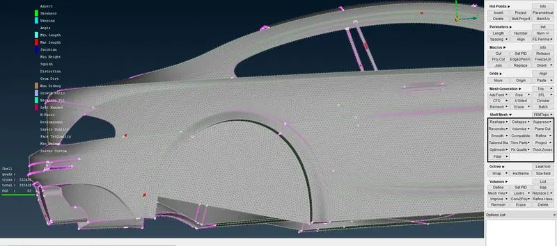
d)Off Elements using Re-construct options ( in Shell Mesh module)
e) AFter recontructs and adjusting the elements with Zero Off Elements
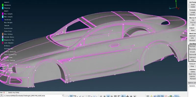
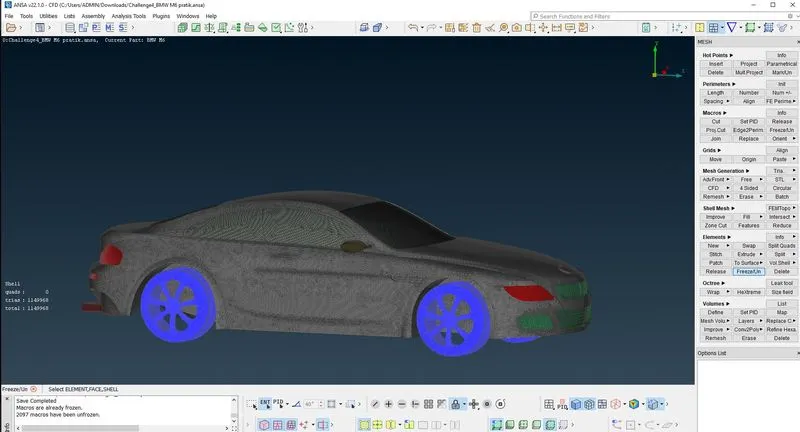
3.3.7] WHOLE CAR BODY WITH ALL PIDs is
3.4] Wind Tunnel -
To create Wind tunnel, first reference points are required to create where wind tunnel surfaces will take shape.
New points have been created using the "Relative" command available in Point toolbar in TOPO deck. Relative command creates new points with reference to existing reference point.
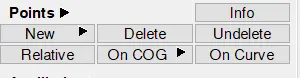
From the reference point, which is considered as hot points in the floor, the dimensions of the vehicle has been measured to add into the wind tunnel dimensions. The below table shows these dimensions.
| From Reference Point | |
| Car Front | 650 mm |
| Car Backside | 600 mm |
| Car Rightside & Leftside | 230 mm |
The wind tunnel size has been considered as per below table.
| Wind Tunnel Dimensions | |
| Car Length (x) | 1300 mm |
| Front | 4x + Car Front |
| Rear | 6x + Car Back side |
| Top | 3x from Roof hot point |
| Bottom | 75mm from Car bottom safety cover |
| Right & Left Side | 1x |
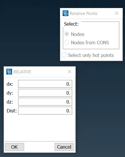
First, points for the bottom surface & four corners of the wind tunnel has been created. The bottom face has been created just some distance below the tyres to study the aerodynamics characteristics under the floor. Following is the Relative point dialogue box. In the Relative dialogue box, the direction has been inserted using the "1" in case of positive axis direction or by "-1" in case of negative axis direction.
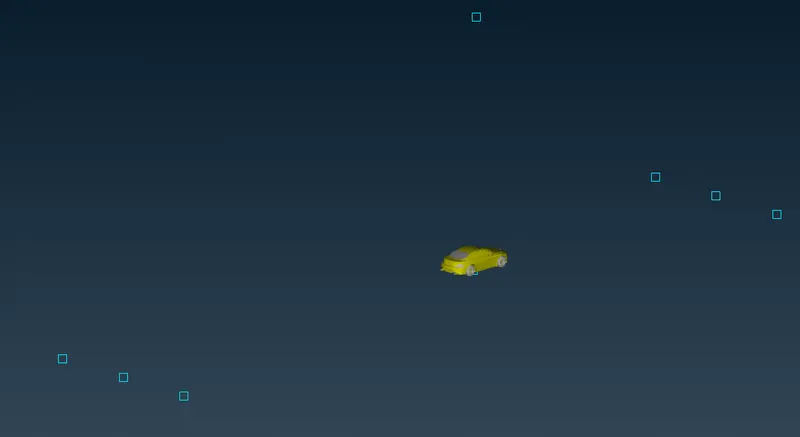
Below image shows the referece points created using above method.
The rectangle shown has been created using the "Create" command available in Curves toolbar.
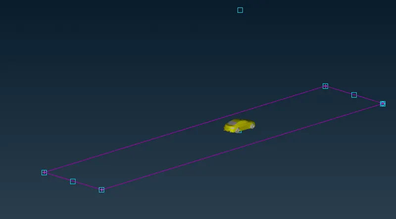
"Create" command

New surface has been created using "New" face command. And top surface has been created using "offset" comamnd.
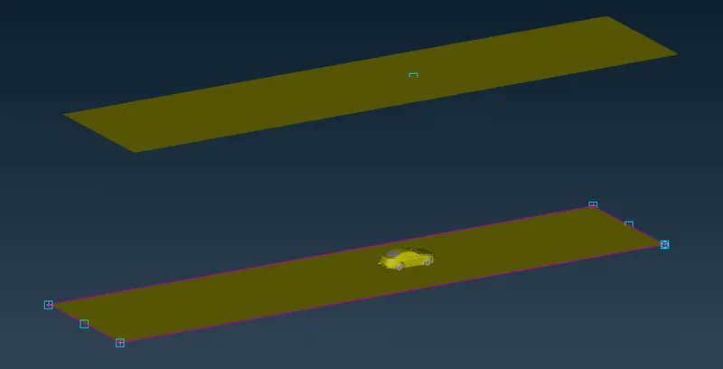
The rest of the side, front & rear surfaces has been created using "New" face command. And respective PIDs was also created.
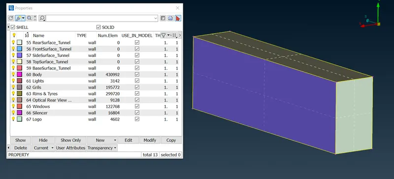
Wind Tunnel Meshing:
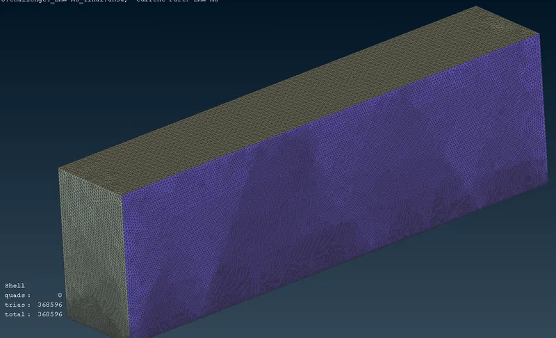
To create meshing, the top & bottom surfaces has been given element length of 100mm & 20mm respectively. All side edges needs to be divided into "Spacing" command to create elements with increasing size from 20mm to 100mm to accommodate between bottom & top surfaces respectively. The "Spacing" command is available in Perimeters toolbar.
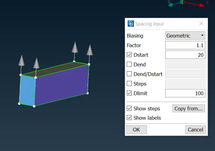
Final surface meshing of wind tunnel:
3.5] Volumetric Mesh -
To create volume mesh, single volume between wind tunnel & outside surface of the car is required to form & all the other volumes is needed to be deleted. Using "Define" command in Volume toolbar in Volume mesh deck has been used to detect the number of independent volumes present in the model.
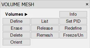
Below image shows the result of this command.
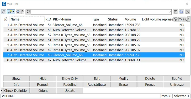
Out of these 8 internal volumes, only one is useful to make the wind tunnel which is mentioned under Auto Detected Volume (2nd from top) & the rest has been deleted. To generate the volume mesh, the required computaion power is very high and because of that the volume mesh has not been performed. Below image shows the wind tunnel with One unmeshed volume.
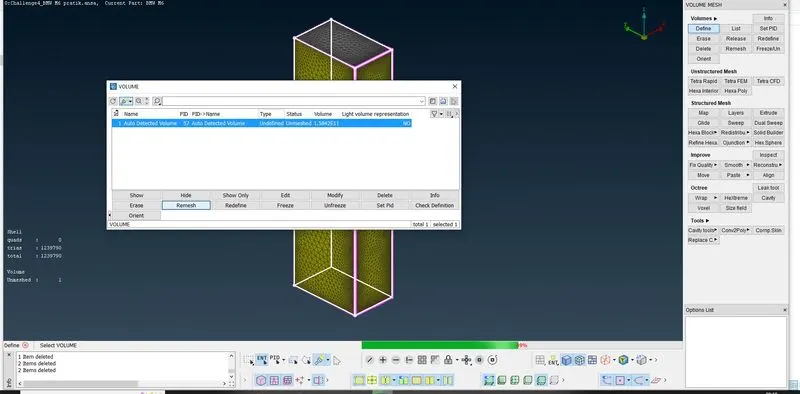
Above Figure Shows the Required MESH VOLUME
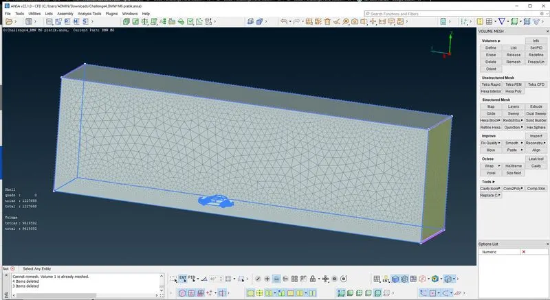
Complete Whole Volume
4] Results and Outcome -
- Form the meshing images we can clearly see the smooth transition of elements from one PID to another.Also there aren't any unmeshed surfaces,also off elements present.All elements follow the given element quality criterias.
- By using symmetry we can see that topo cleanup and mesh gets successfully replicated to the other side.
- ANSA successfully detected volume between wind tunnel and car model and this will be use to generate volumetric mesh, which can then be use in CFD simulation.
- By using half car model we significantlly reduced the memory usage and also computation time.
5] Conclusion -
- We have successfully performed topology cleanup on the given BMW car model and resolved single cons and removed all overlapped surfaces.
- Successfully generated surface mesh,which is pre requisite for volumetric mesh and created wind tunnel and meshed it.
- Also learned what is volumetric mesh and how to performe volumetric mesh.
- Thus we have successfully generated volumetric mesh for the give BMW car model for CFD applications.
6] Link -