Week 4 Challenge : CFD Meshing for BMW car
AIM: -
To perform volumetric (CFD Meshing) on the given BMW car geometry.
->ANSA- (Automatic net generation for structural analysis) is a computer-aided engineering tool for Finite Element Analysis and CFD Analysis widely used in the automotive industry. It is developed by BETA CAE Systems [Source: - Wikipedia]
->It is used for pre-processing task and it includes proper clean-up like a geometric clean up.
-> 2D & 3D it is very widely used in CA applications.
->ANSA maintains the association between CAD geometry and the FE mesh.
Objective: -
For the given model, check and solve all geometrical errors on half portion and assign appropriate PIDs. Perform meshing with the given Target length and element Quality criteria. After meshing the half model, Do symmetry to the other side.
- Target lengths for the different parts of a model are as follow:
- Body - 3 mm
- Lights - 4 mm
- Grills - 1 mm
- Rims and Tyres - 2 mm
- Optical Rear-view mirror - 2 mm
- Window - 2 mm
- Silencer - 3 mm
- Logo - 1 mm
Procedure: -
Step 1: - Importing the CAD Model
Go to the file - > open the file - > Search the location, where the CAD model is present- >Supposed another model is open in workspace then it will be discarded or saved - >Certain path where we had download or save the model, It can be identified by ‘’Turbocharger ANSA’’ - >Select it & click on enter.
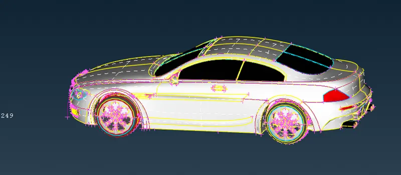
Step 2: - Geometry clean-up
As we can see in above figure that the whole model surface is not in uniform/accurate. For that we can use FIT tool that is present in the TOPO_ > AUXILIARIES _ > FINE but this is a long method we will be using MESH _ > PERIMETERS_ > LENGTH _ > PERIMETERS & MACROS tool with the length 1mm. before doing this step we will be using TOPO clean up so that the some of the single cons gets converted in to double cons.
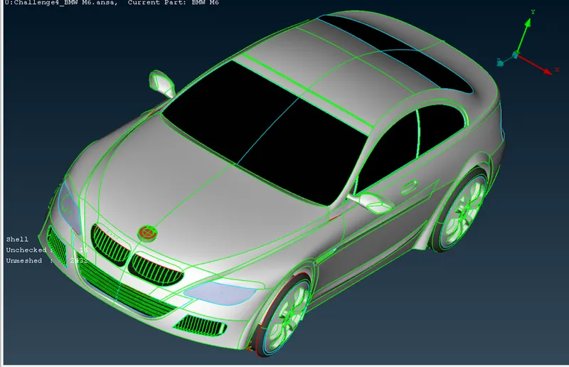
Now we can see single cons by using wire mode [ control+shift] & also triple cons, since once we solve both single cons as well as triple cons then we can go for a meshing mode.
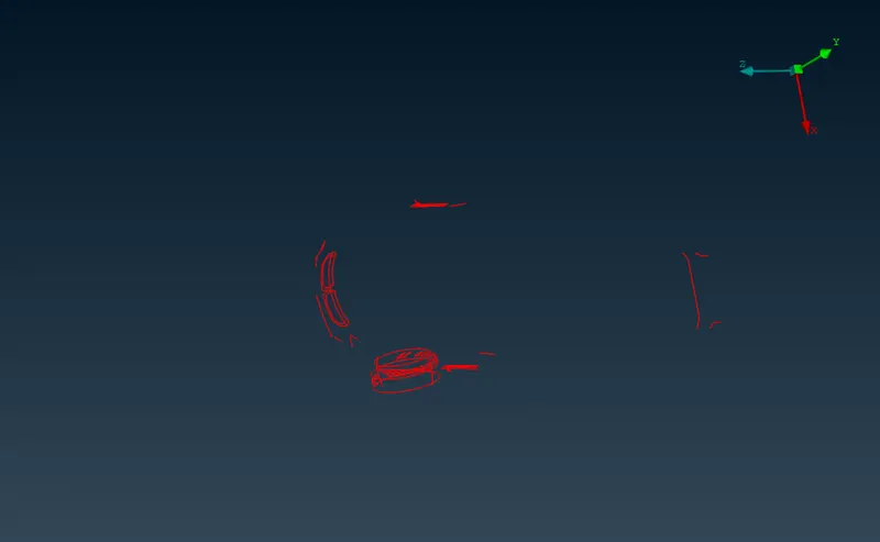
In ANSA there is a feature or tool we can use in this model;
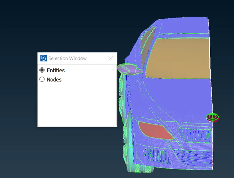
we can delete half of the model because in this case the model is symmetric on both side except for BMW Logo. we shall select the half model and deselect the BMW logo by using right click of mouse button the purpose of doing this after doing all the operations half of the model we can use symmetry tool [Transform_ > Copy_ > Entities_ > symmetry] to copy half model on other side.
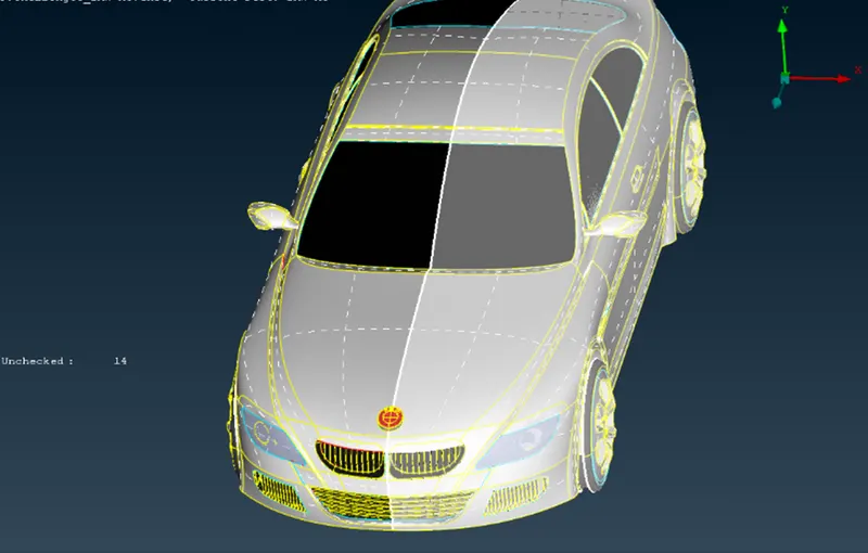

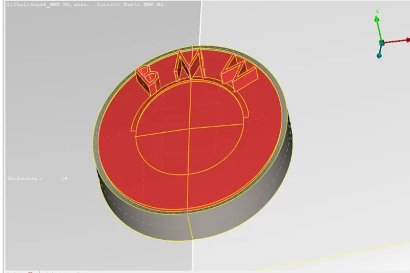

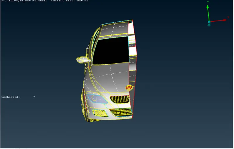
Since after doing this, we had to delete the inside surface of the car because we had to mesh the model.
Now we are going to isolate the car parts like front Grills, Logo, Wheel and Rim, Lights, Window, Mirror, Silencer, and body so the purposes of doing this to delete the unwanted & Overlapped surface and using the universal delete tool for deleting the faces where it is required. After deleting the surfaces we will create the new faces with the help of coons or fitted etc [ Classic TOPO __ > Faces __ > New ]
So, we had deleted the inner surface which we will not require for meshing.
Front Grills
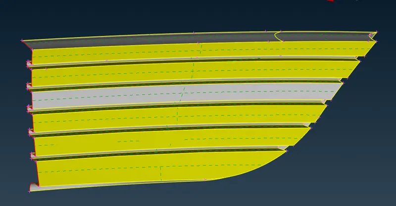
Imp Point, some of the time if you are willing to change the single cons to double cons through TOPO or project tool but its not happening due to we had to select a small region so that the TOPO tool work on it.
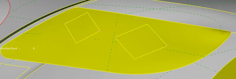
Headlight
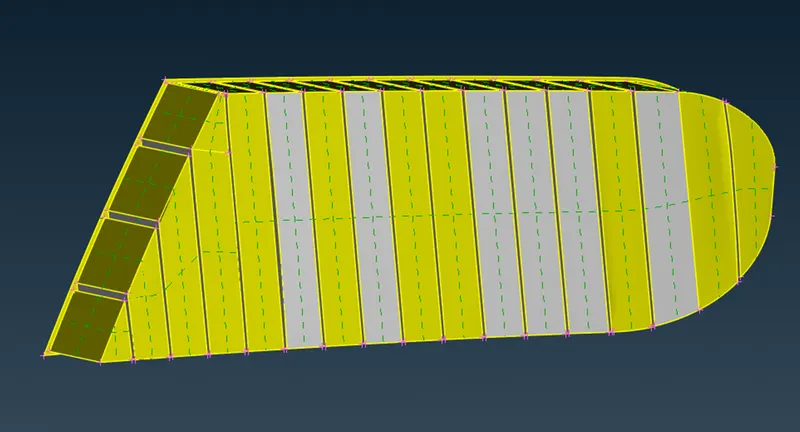
Grills
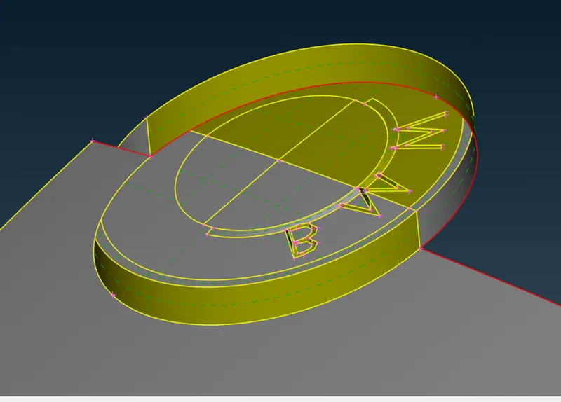
Logo
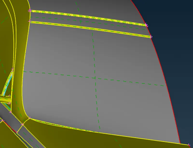
Side & Front mirrow
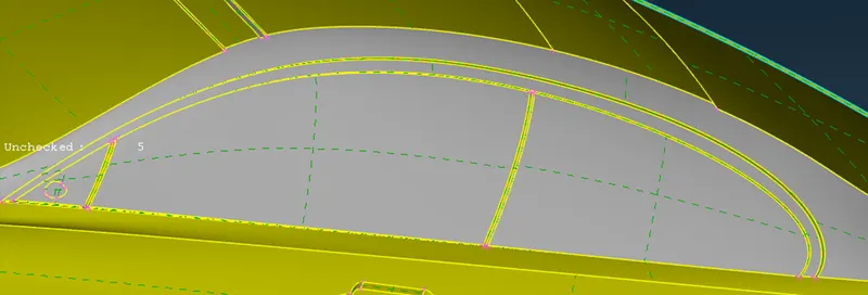
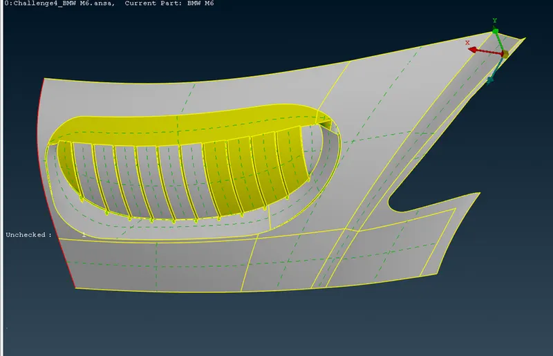
Mirror
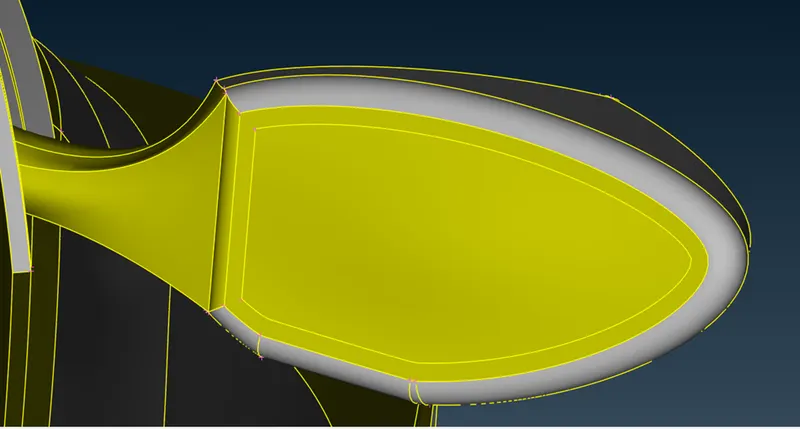
Inside mirror
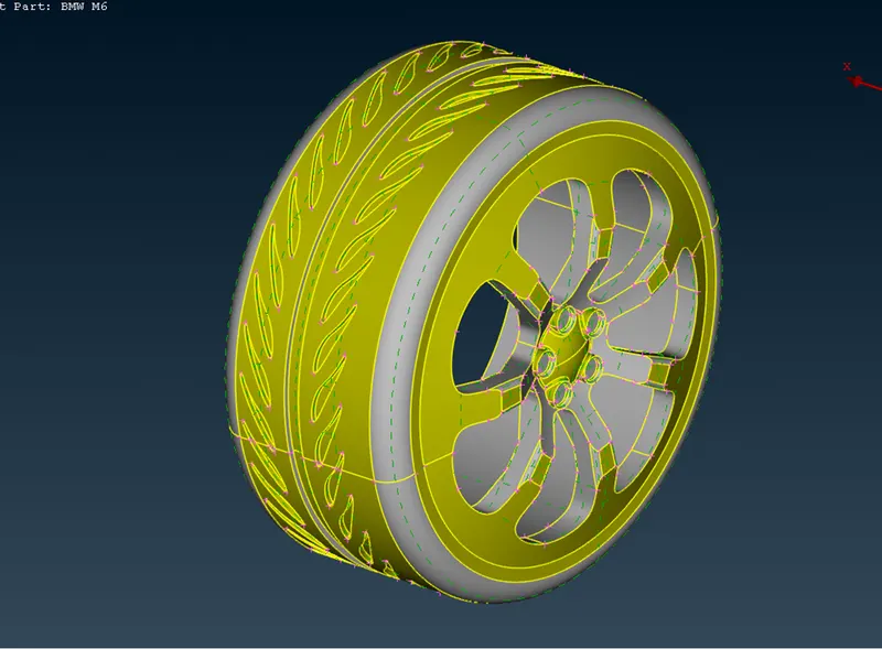
Tyre
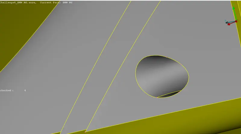
Since after deleting almost all the double cons, single cons & overlap surface, the last and the crucial step was to delete the surface of bottom of the car. After doing all the steps we use geometric checks to find out the double cons, single cons & overlap surface
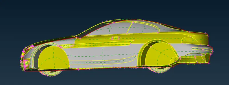
Step 3: - Assign PID
Steps for PID assign…. Properties _ > Click _ > New pop-up box, It will shows the Pshell contain or PID
How to create a new PID?
To create a new PID_ > Right click _ > New _ > Pshell _ > new box will come up _ > Name (e.g.:- Outlet) _ > OK _> Properties new PID present _ > we can also change the colour by clicking twice on this □
To assign PID _ > Click on the PID, which has to apply on our model _ > Right click _ > Apply _ > Go to the model _ > Take the cursor to the Cross edge / face and click centre button.
How to delete extra PID _ > Select the PID _ > Go to the compress tool which is present in upper row, as shown below.
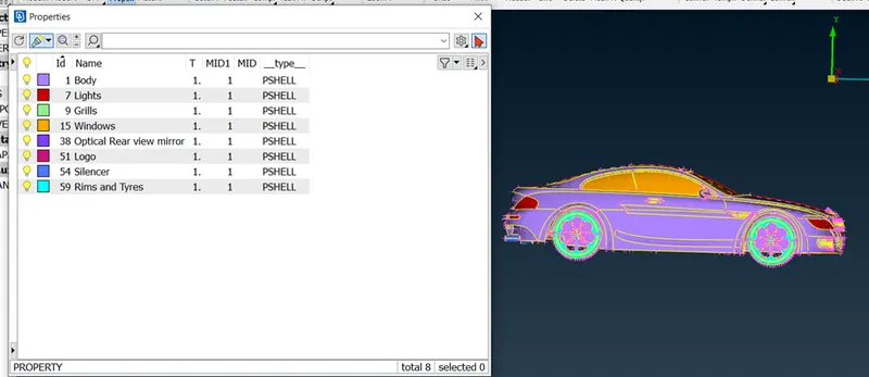
Step 4: - Meshing
Target lengths for the different parts of a model are as follow:
- Body - 3 mm
- Lights - 4 mm
- Grills - 1 mm
- Rims and Tyres - 2 mm
- Optical Rear-view mirror - 2 mm
- Window - 2 mm
- Silencer - 3 mm
- Logo - 1 mm
Element type = Tria
In this meshing we will be using open foam tool [Symbol- 
Using Quality Criteria tool for adding or removing Criteria we are going to follow some step i.e. Click on Quality criteria __ > Tab open __ > In section SHELLS in that if we would like to add or remove, we will be using edit criteria option __ > for Changing the criteria values we need to select or tick the box
In Quality criteria if we are choosing 2D elements we will be going for Shells similarly for 3D elements we will be going for solid.
Since in this model we will be using quality criteria, if the assume length of minimum value observed is less then we will be using the cut tool to increase the distance between the nodes or cons.
The below picture represents the PID of body, in these the length observed is less than the minimum length so used he cut tool.
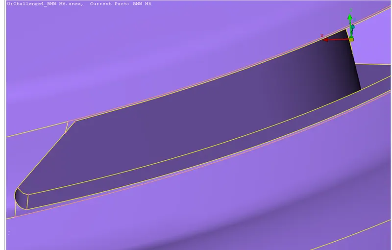
Similarly, will be checking for each PID before meshing this model. If the values fail then we will be using cut tool as used for body PID. Supposed if in some cases we cannot used cut tool for increasing the distance in-between values we will be using the minimum length so that while meshing it will not fail.
Select Classic MESH tool - > In that we had to go in perimeters after then click on Length.
- > choose the perimeters and to select the whole model we have to drag down the cursor and select the whole model, later we had to click the mouse centre button - > In length we have to give the number 1 as shown above for logo we had used to..
> Since after doing this for perimeters we are going to do exactly similar for macros.
Since we are moving for a mesh parameters and Quality criteria.
Select Mesh parameter - > In basic we had to choose the element type has TRIA and in mesh size the target length should be 1
Quality criteria _ > Tick all the parameters as shown in below picture _ > Minimum Criteria should be 0.4mm and maximum Criteria should be 3mm _ > Click on Apply
- Now using Visible to provide the meshing in all parts of the turbo charger
For Visible _ > Mesh generation _ > spot mesh _ > Visible
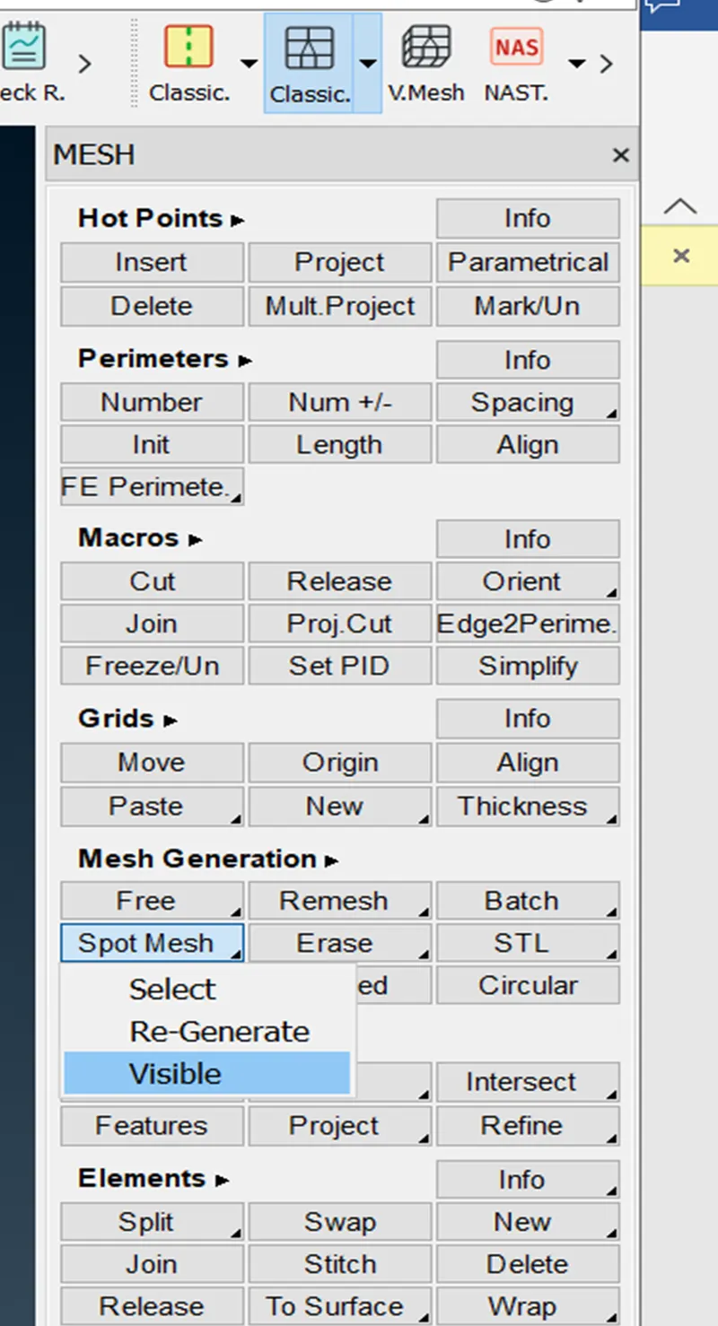
Meshed Element with the target size of 1mm
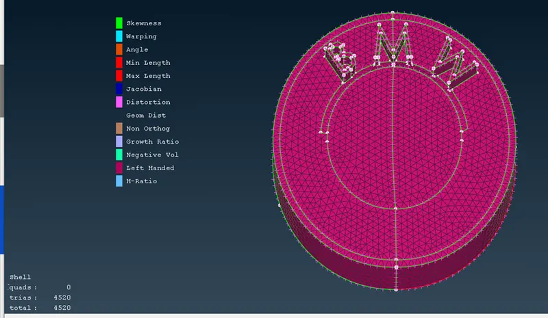
The total no of elements under 1 mm is 4520.
Similarly, we will be doing for grills because it has same target length so we do not need to change the perimeters.
Grills
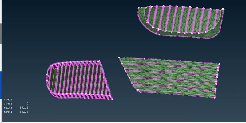
The total no of elements under 1 mm is 95212
Windows
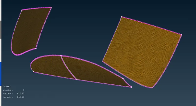
The total no of elements under 2 mm is 61363
Rims and Tyres & Optical Rear-view mirror
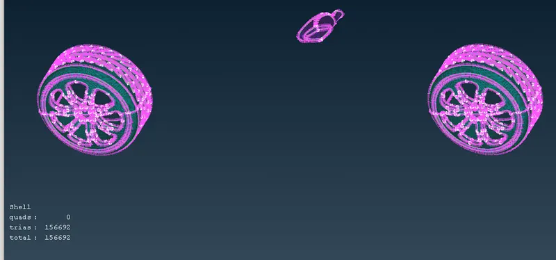
The total no of elements under 2 mm is 156692
Lights
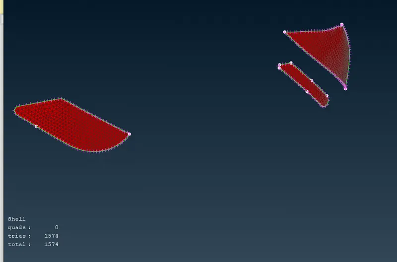
The total no of elements under 4 mm is 1574
Silencer
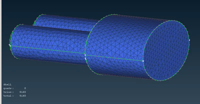
The total no of elements under 3 mm is 8140
BMW CAR
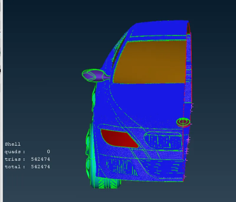
The total no of elements is 542474
Note:- We can use freeze tool which is present in Mesh__ > Elements __ > Freeze
As we know that if we use different target length at two different surface or different PID then the mesh will only appears at one of the surface with that target length, so for this we will be using freezing that surface so that we could mesh two surface at different target length.
Step 5: - Using the Symmetric tool
We will be using symmetric tool by using the transform tool
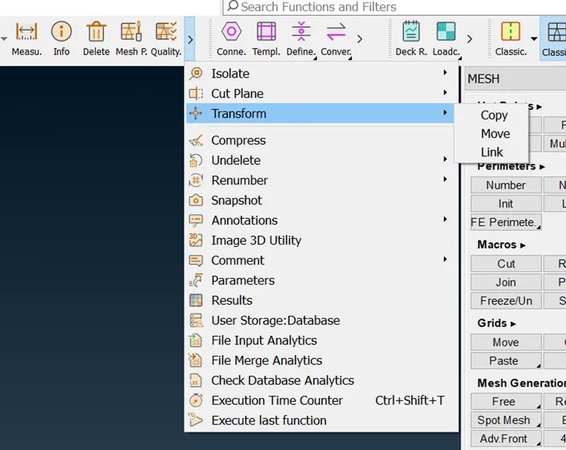
Transform tool __ > click on copy __ > the pop up will appears in that by default the entities is selected so don’t change it __ > use the shift button and simultaneously drag down the mouse and selected the whole model [ while selecting remember the box colour should appears in red colour ] and deselect the BMW LOGO with the help of PID __ > Click centre mouse button __ > one more pop will appears in that we should select the symmetry , then after select the three point at the top of the model so that it will detect the axis point i.e., x ,y & z .. Click centre mouse button __ > one more pop up appears don’t change anything .. click Ok or Click centre mouse button it took couple of minutes or secs after that the model appears as fully meshed along with the PID but do not cancel the tab just use ok button or apply to remain same as it is.
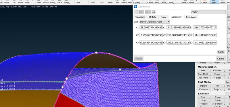
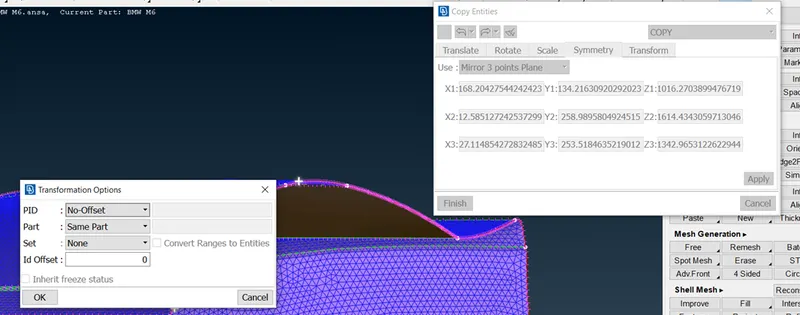
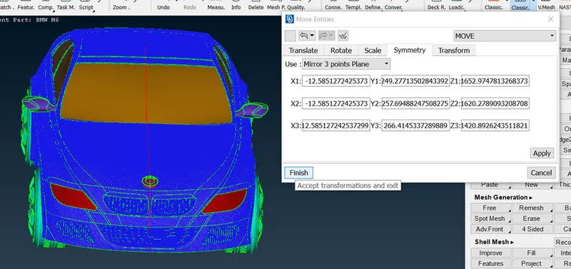
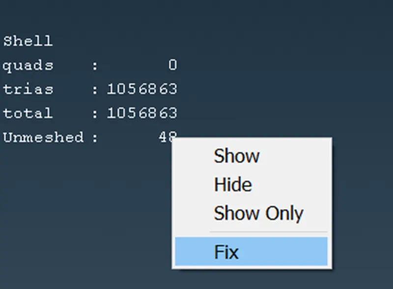
Once the model is completed then there would be single cons present, So we can use topo tool or paste tool to get into double cons. So in this I have used the freeze tool so first I have to unfreeze this command to apply the topo or paste tool. Once I have used unfreeze the whole model most of the surfaces gets unmeshed for that we can use the normal method of meshing or we can directly fixed all unmeshed surface at a time with the help of fix which is present unmeshed for more understanding the picture is attached below,
Step 6: - Wind Tunnel
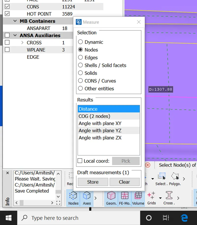
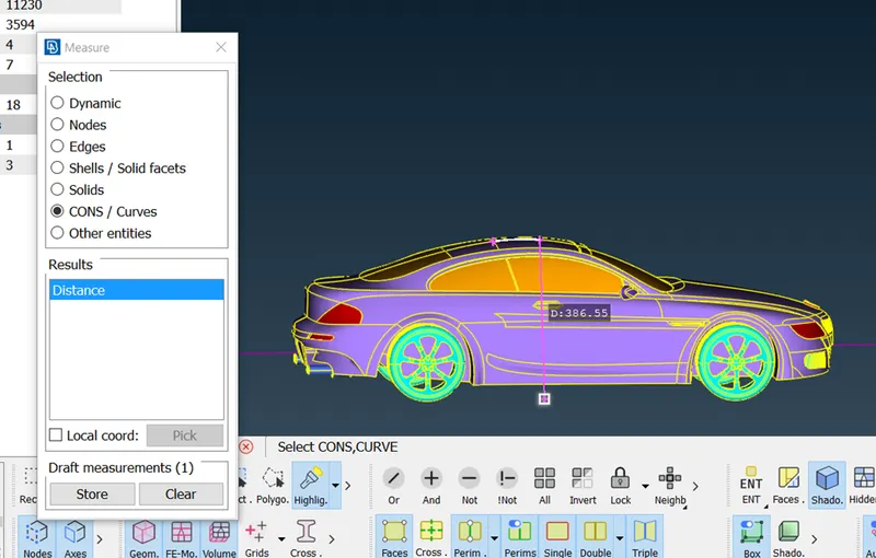
In wind tunnel first we have to measure the length of the car with the help of measure tool as shown below, the car total length approximately is 1300mm
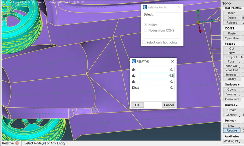
Let’s create a points which is present in TOPO __ > POINTS __ > Relative__ > Click the centre of the car from the bottom side as shown below in picture & later we had put the values in Y-axis as -75mm because the “ – “ sign indicate downwards axis as we are aware about quadrants.
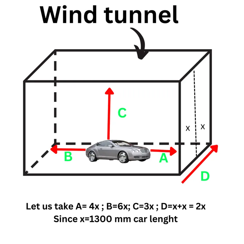
Since WKT front side of the wind tunnel is 4x + the distance of the half car and the total values occurs is 5850mm and uses the same method to create the points as shown below,
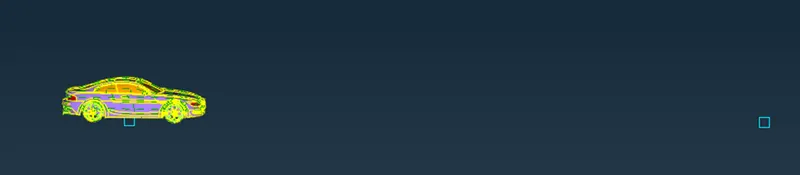
Similarly, we will be doing for back side or rear side of wind tunnel i.e., 6x + the distance of the half car and the total values occurs is 8410mm and uses the same method to create the points as shown below,

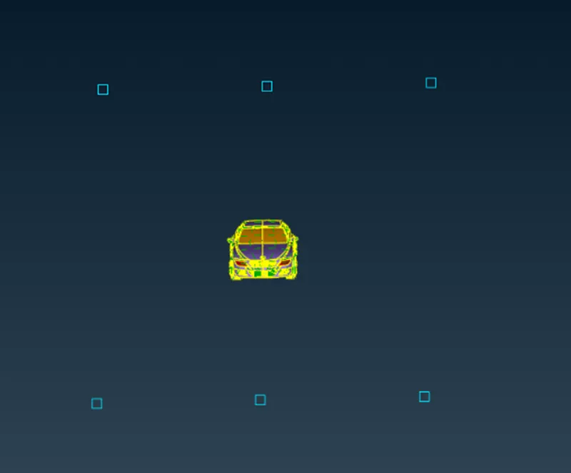
For top surface the distance is 3x for the wind tunnel randomly insert the hot points at the top surface to take a reference of +3x

For the side wind tunnel surface, we had to use the top view of the model use to 2x as a distance from the front point 4x and the back point value i.e., 6x since the value will be -1300, +1300
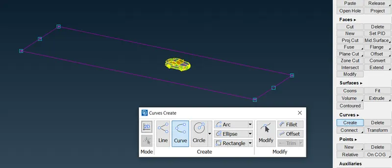
Now will be connecting those points with the help of curve which is present in TOPO__ > Curve __ > Create
Now we had to create the new faces and to assign the PID
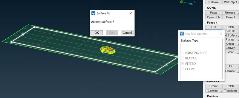
After assigning the PID we are deleting that upper point because we will be using the offset tool which is present in TOPO __ > Faces __ > Offset __ > Value for upper surface, since we are inserting the value in negative since the arrow direction is in negative quadrant
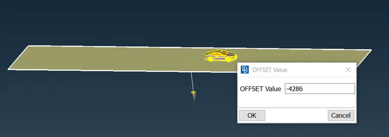
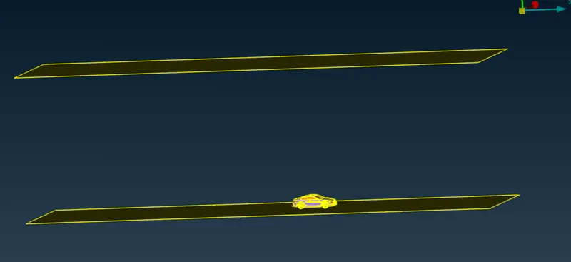
Once the above surface has appears we going to delete the curve and the points which are created for the references & going to crated all the surfaces and assign the PID.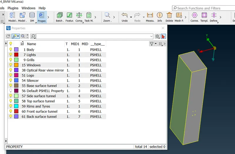
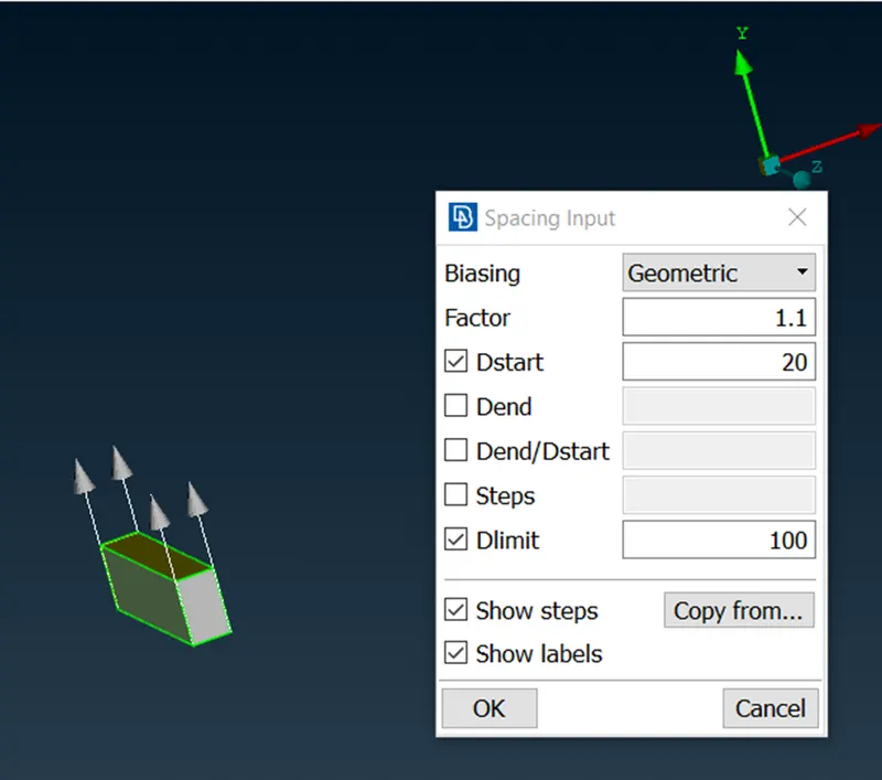
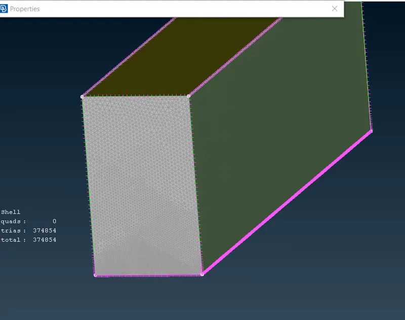
Now we are moving towards the meshing since for top surface target length 100 mm & Base surface target length 20 mm and for front and back surface we will be using spacing tool which is present in perimeters, since the values we are taking is Dstart is 20 mm because it starting from base surface and gradually increases the Dlimit is 100 mm ending at top surface, since in this we won’t be considering the quality criteria and mesh perimeter because it gradually increasing
Now Volumetric mesh
Before using V-mesh, we had to mesh the whole model.
V-mesh _ > Volume _ > Defence _ > Ask whole DB[data base] or visible , Go for whole DB _ > Click OK _ > Volume list appears or volume list can be select under the volumes
https://drive.google.com/drive/folders/1UmQQ4D1KCHl9HJyMgw657IoEN-RB33P9?usp=share_link