Week 4 Challenge : CFD Meshing for BMW car
Aim:
The aim is to create the single volume between BMW car & wind tunnel to perform external aerodynamics
simulations.
Objective:
For the given model of BMW car, check and solve all geometrical errors on half portion and Assign appropriate PIDs. Perform meshing with the given Target length and element Quality criteria. After meshing the half model, Do symmetry to the other side. And also develop wind tunnel with appropriate mesh.
1. Target lengths for the different parts of a model are as follow:
2. Body - 3 mm
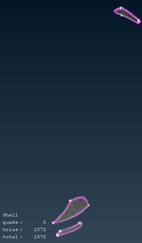
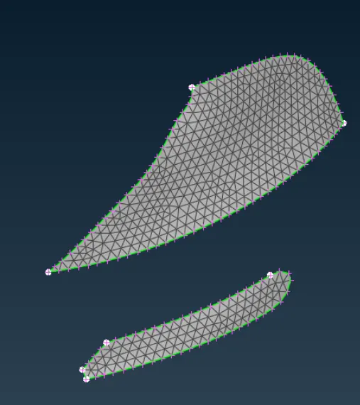
3. Lights - 4 mm
4. Grills - 1 mm
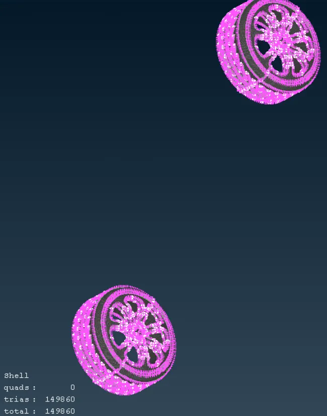
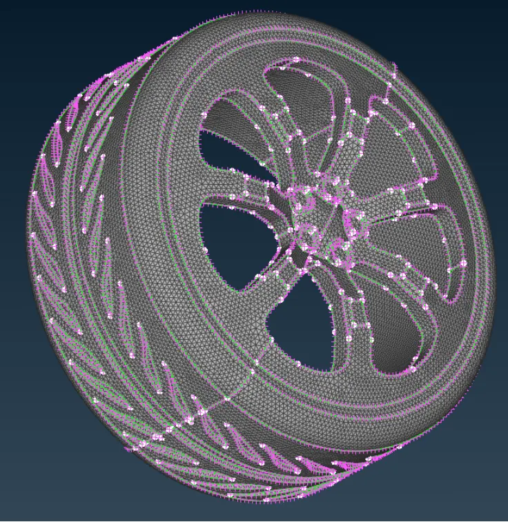
5. Rims and Tyres - 2 mm
6. Optical Rear view mirror - 2 mm
7. Window - 2 mm
8. Silencer - 3 mm
9. Logo - 1 mm
Answer:
To achieve the aim of the project, the secondary surfaces available on the back side of the components need to be deleted &
Received Model:
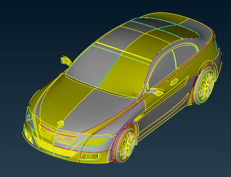
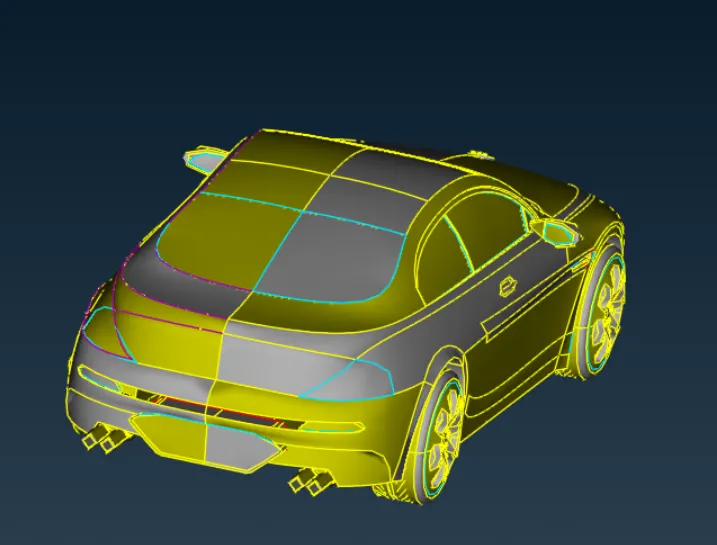
The resolution the received car model was very low and because of that the edges of the vehicles are not in their better shape. This causes the misinterpretation of the shape of the component.
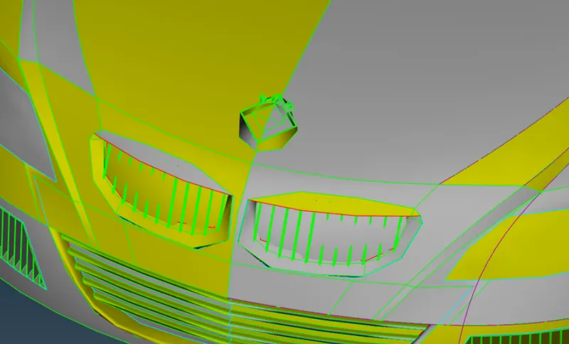
The "fine" option available in Auxiliary section of Topo deck is used to increase the resolution of CONS, but it will take lot of time by increasing resolution of all CONS one by one. The resolution has been increased by using "length" option available in perimetersection of Mesh deck. The perimeter & macros size has been kept at 1mm.
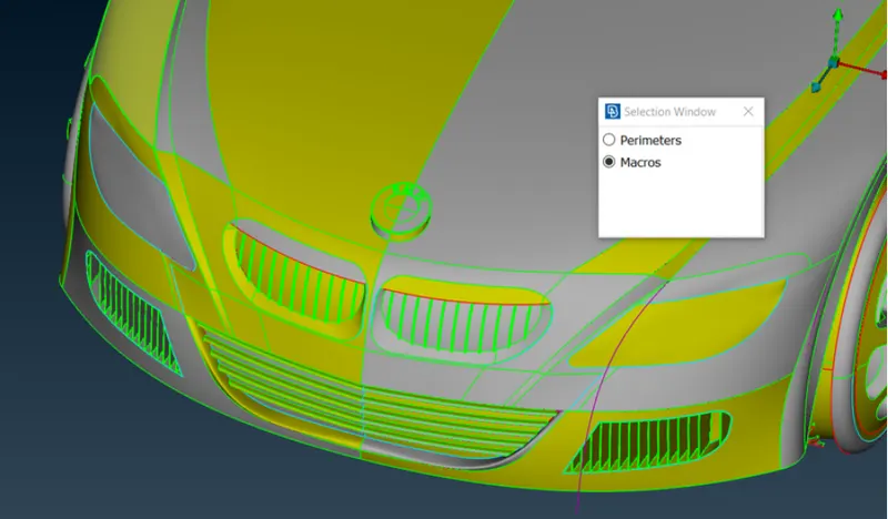
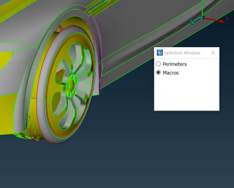
The model has many single & triple cons and also it has warped, overlapping, missing & damaged surfaces. As the car is symmetrical except the logo of the company, the half of the model has been deleted. And the half model is improved & corrected for the problems. Later, using the "copy" option, the the half model has been mirrored to make it complete vehicle.
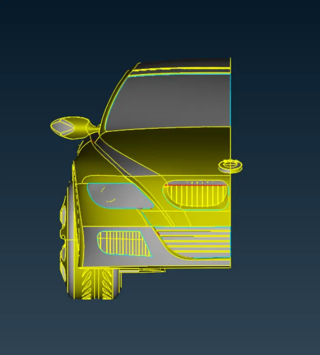
To improve the whole vehicle at the same time is very difficult task, because of that sections of the vehicle has been isolated from the whole model and isolated sections has been improved & made ready for meshing one by one. First section is isolated was front portion of the car. Below image shows the back side portion of the front part. To perform external aerodynamics, the car model has been prepred to make one single volume. The surfaces that make the back structure of the component has no importance in this type of meshing and has been deleted from the model which is part of TOPO clean up process.
In TOPO clean up process,
- The extra surfaces or overlapping surfaces that formed the triple CONS has been deleted from the back side. Triple CONS are responsible for creating small seperate volumes which are not desirable.
- Single CONS has been converted into double CONS by connecting two unconnected surfaces or correcting the 3D modeling mistakes or small surfaces that formed during data conversion which are unwanted has been cleaned.
- The surfaces that form the back structure of any components, the inside compoents like lamps in headlight and the surfaces that form as part of thickness of the compoents has also been removed.
- Extra hot points at difference CONS which create problem while meshing or the points that left after deleting the surfaces has been deleted.
The final aim is to form double CONS in all places to make one single volume.
Following toolbars has been used for TOPO clean up:
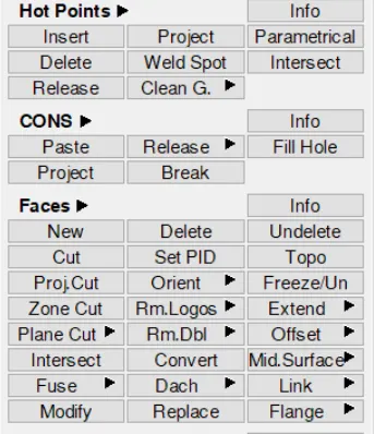
Topo cleanup
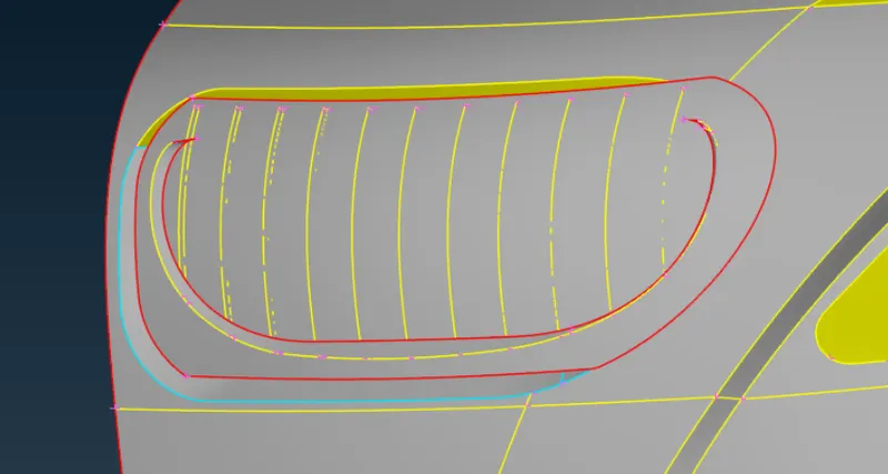
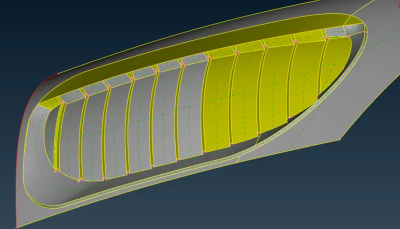
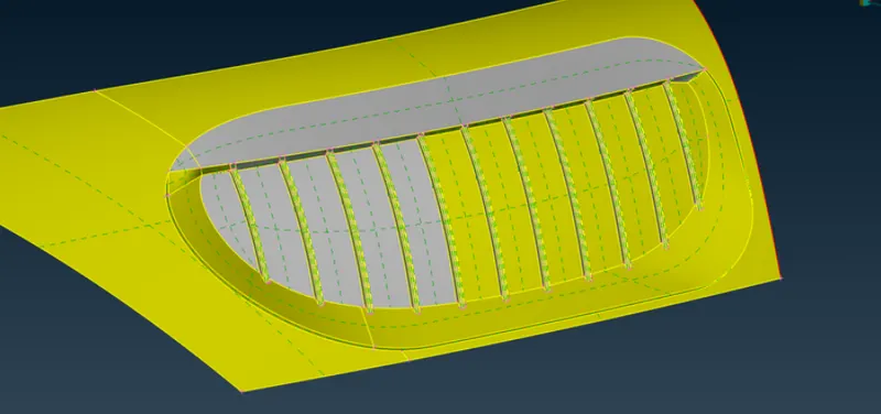
Lower grils &head lights
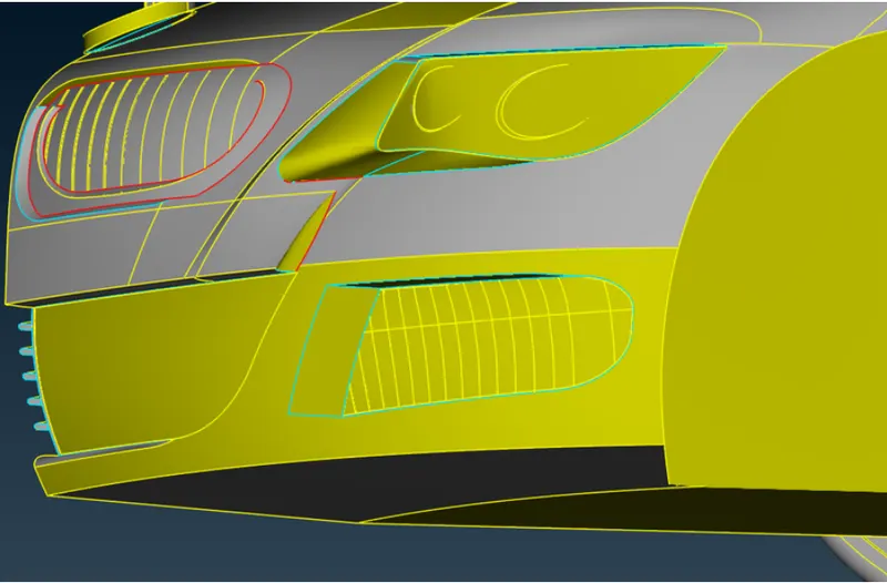
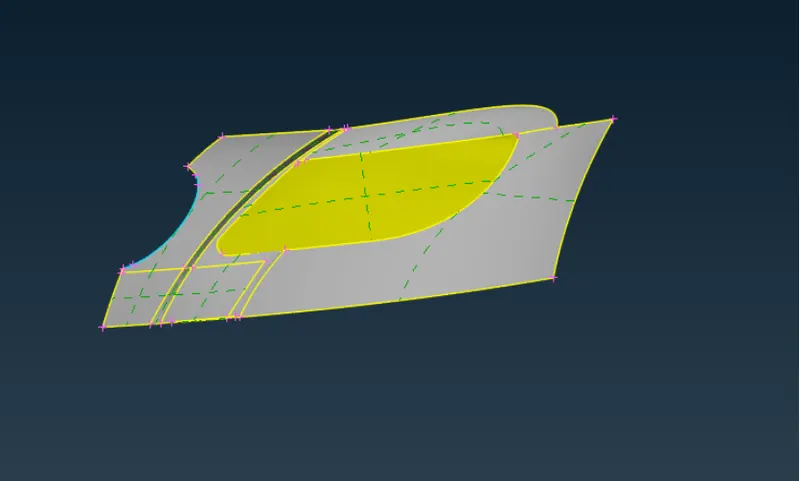
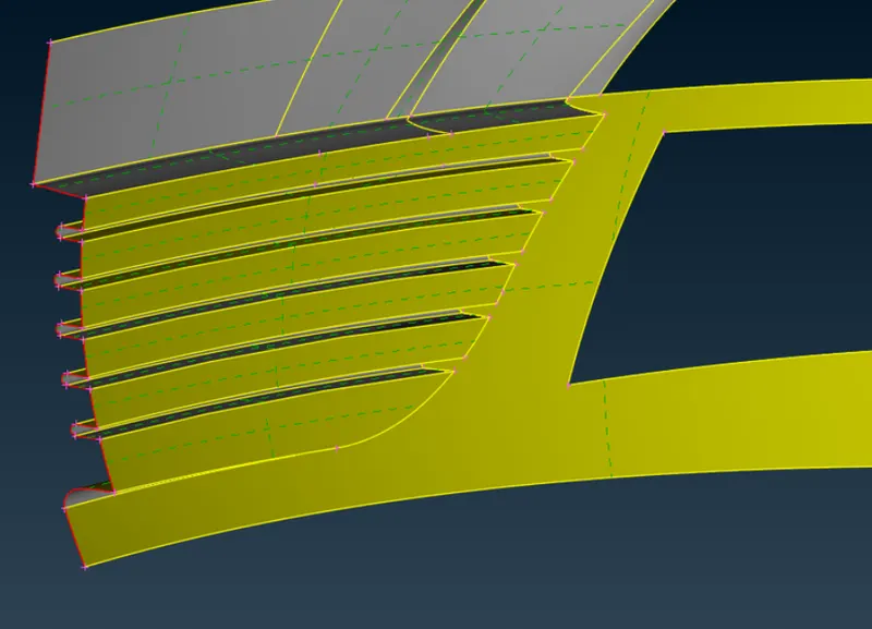
Following images shows the grills & head light section after performing TOPO clean up. And after that other components has also been displayed.
Headlight:
Lower grils
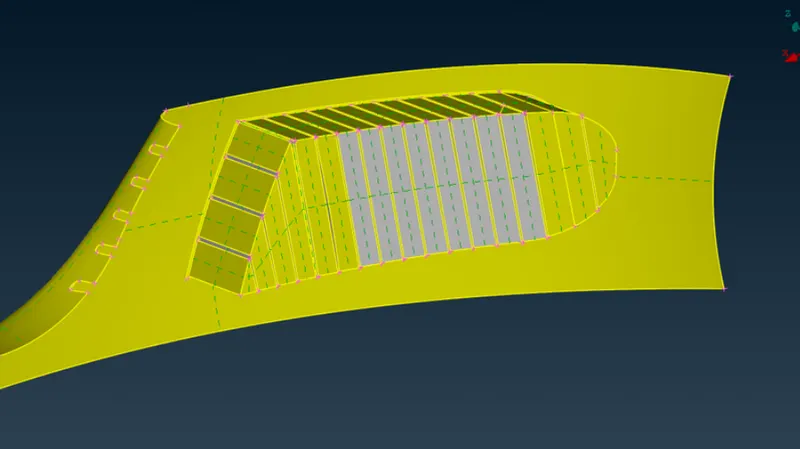
Main gril
initial condition
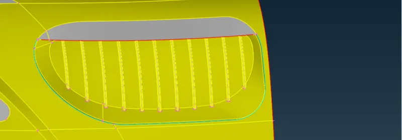
Final condition
Logo:
The logo had the very small surfaces which width was very small compare to the target length of the mesh elements. These type of small faces has been deleted to protect the mesh from failing. But care has been taken while deleting the faces that any faces that are part of function of the components has been kept as it is. And to protect the mesh from failing, the minimum length criteria of mesh element length has been decreased to cover this small important faces.
Initial condition
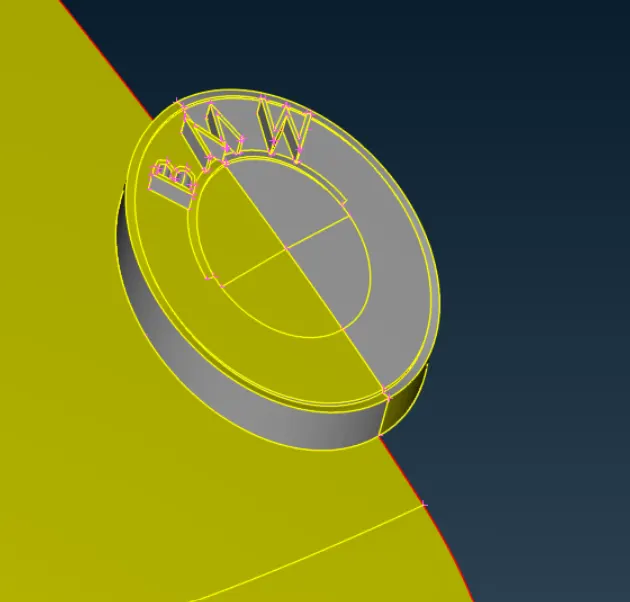
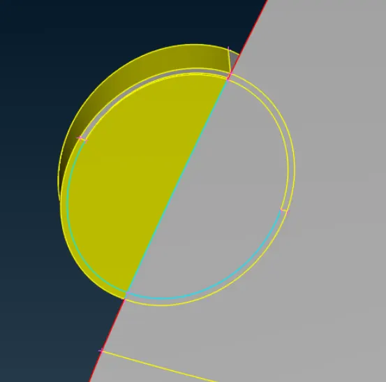
Final
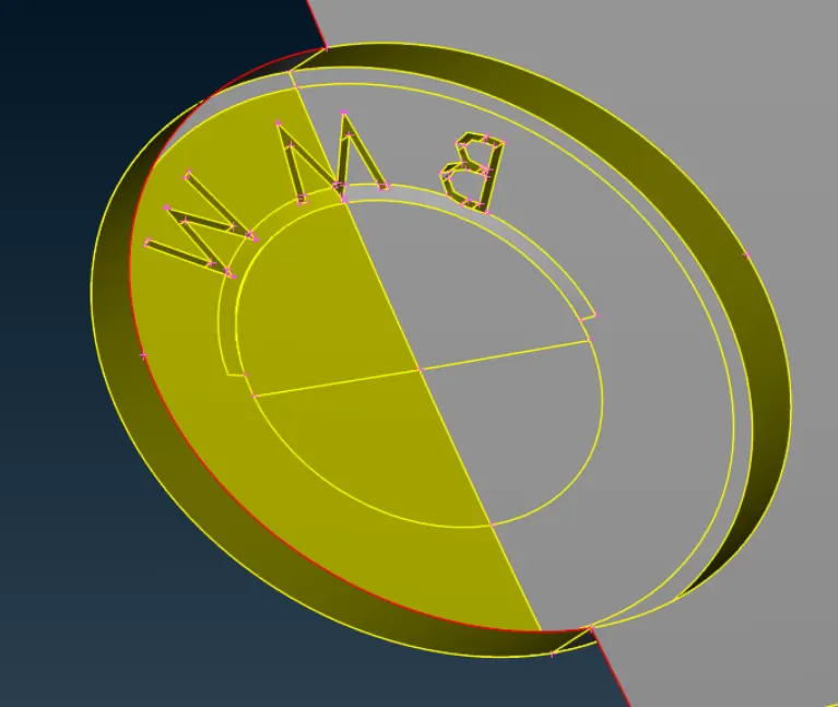
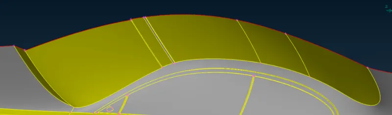
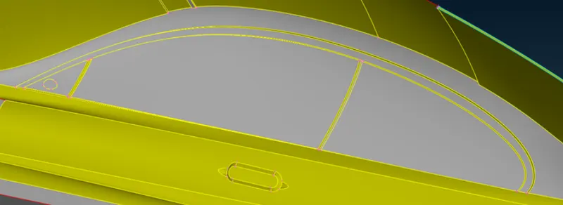
Windshiels & Windows:
Initial Condition
Double CONS has been deselected, so only single & triple CONS can be visualized.
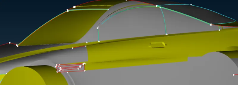
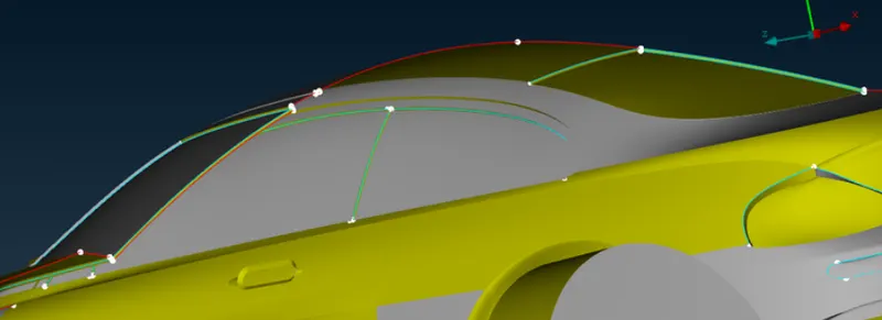
Final:
Solving error and removed single and triple cones
Wheel cover & Floor:
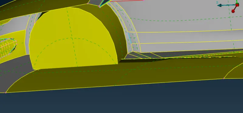
This portaion was in the worse condition compare to other sections. This portion contained the extra surfaces, surfaces intersecting without forming intersecting edges, warped surfaces, overlapping surfaces & unnecessary surfaces.
Initial condition:
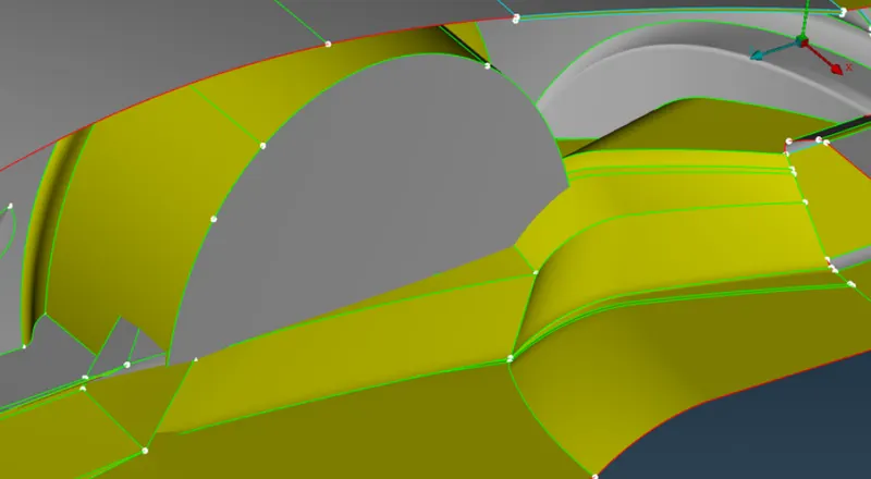
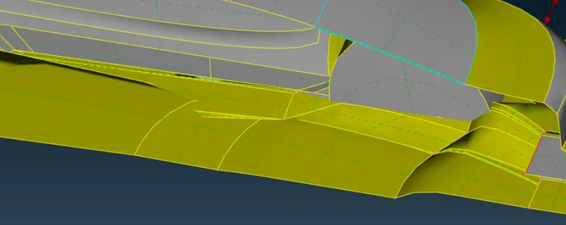
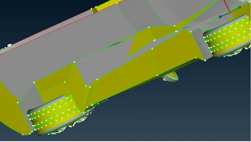
Final:
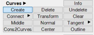
Some portion of the floor has been deleted to form the new surfaces. But before deleting surfaces, curves has been created from the existing CONS using "Cons2Curves" option available in Curves toolbar to preserve the shape of the floor. Following command has been used.
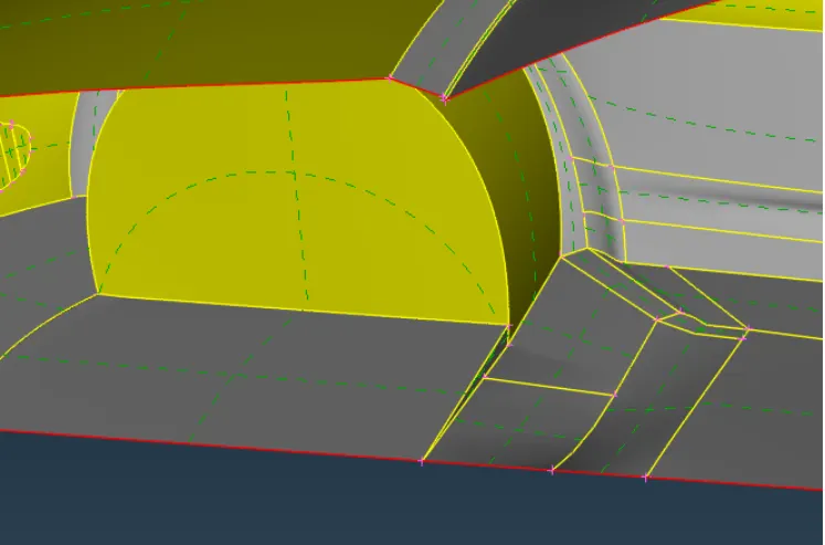
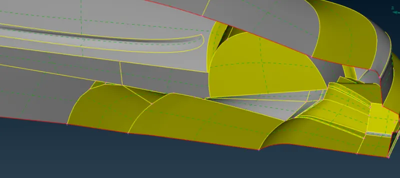
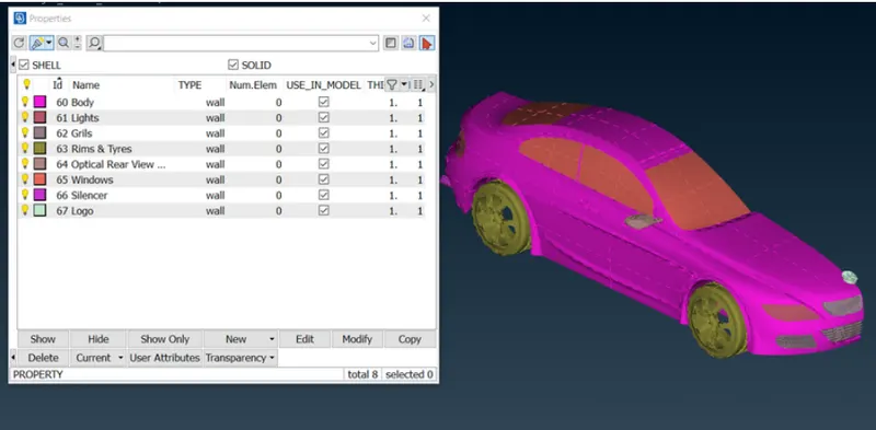
After TOPO clean up, various PIDs has been assigned to the car to divide the car according to their functions. The remaining PIDs has been deleted forcefully which are unwanted using "compress" command.
As per the objective, the meshing needs to be performed as per the element length provided for various sections. To prepare the model to perform the mesh, the smaller surfaces & edges that might create problem during meshing has been cleaned by removing extra double CONS at that place. To find these smaller surfaces & CONS, "measure" command has been used to measure the smaller CONS that might fall below the required mesh element length.
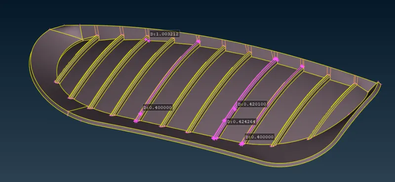
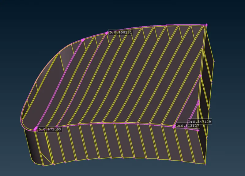
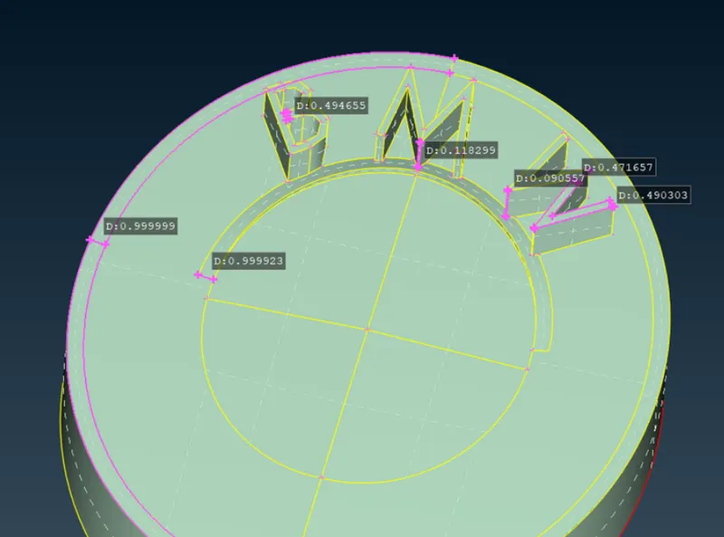
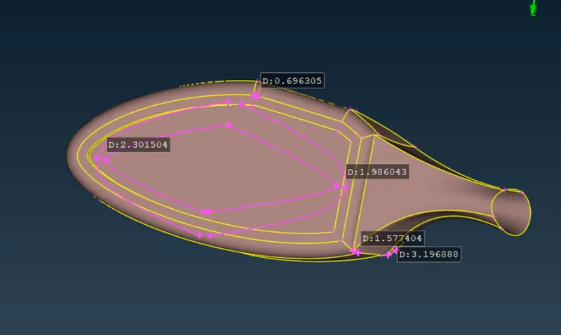
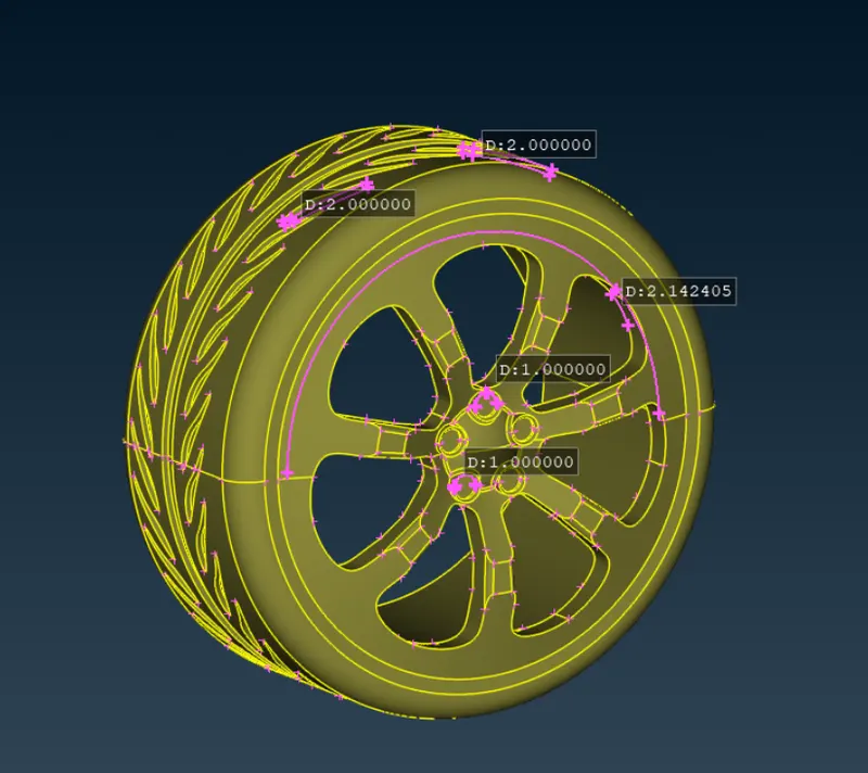
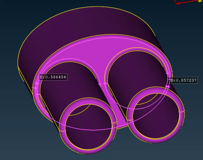
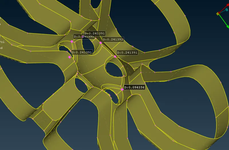
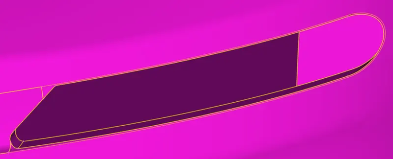
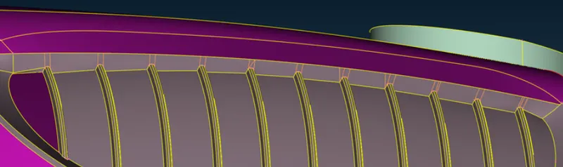
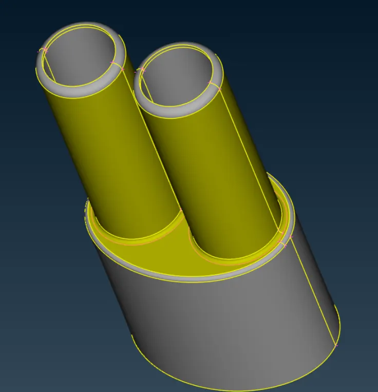
Following images show the variuos sections of the vehicle from where the double CONS has been removed. The double CONS in orange color are removed using "cut" command available in CONS sections in TOPO clean up deck.

Meshing:
Before perfomring meshing, few steps are required like setting Mesh parameters, Quality criteria & applying the desirable length to perimeters & macros (surfaces) using "length" command.
Logo:
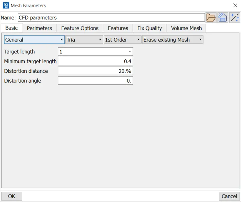
In Mesh parameters dialogue box, the target length has been entered after selecting General criteria & mesh type has been selected as Tria. Targer length & minimum target length has been entered for the respective PIDS requirements.
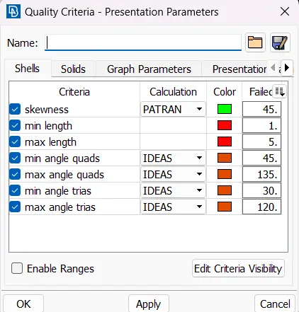
In Quality criteria dialogue box, the criteria has been considered for Fluent applications & seven criterias has been assigned to check for the quality. The criterias has been considered which are ticked in the below dialogue box.
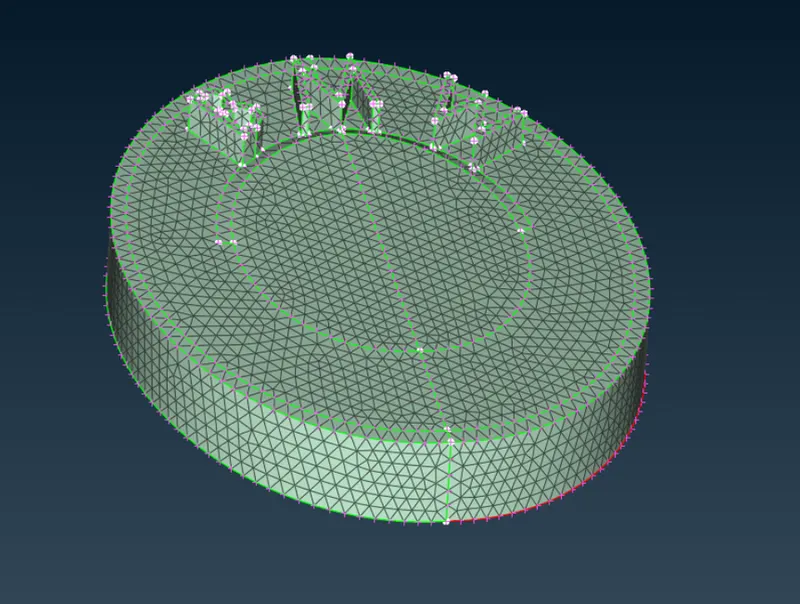
Meshed component
Mesh parameters & Quality criteria has been entered as per the below table. The quality criteria for Skewness, Min & Max angle quads and Min & Max angle trias has been remained same for all PIDs as mentioned in above image of quality criteria for "logo" PID.
Mesh Parameters (mm)
PID Target length min length max length
Grill 1 0.3 2
Optical Rearview mirror 2 1 3
Windows 2 1 3
Rims & tyres 2 1 3
Lights 4 3 5
Body 3 2 4
While performing meshing, some elements which dont fulfil the quality criterial, fall under the offset elements. To resolve these issues, commands from following toolbar has been used.
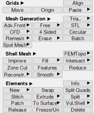
First of all "Reconstruct" command has been used from "Shell Mesh" toolbar to reconstruct mesh elements. Most of the problems are getting resolved after using this command. The elements that are still facing problems have been resolved using "Move" command available in Grid toolbar or using "Split" command available in Elements toolbar. The Move command helps the user to slide the mesh grid to change the shape of the elements to solve the issues of element sizing or the issue of skewness. The Split command helps in dividing the elements which are facing issues of either max length or skewness.
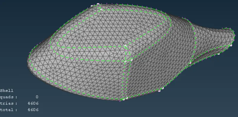
Following image of Mirror shows the offset elements which are required to resolve before moving into volume mesh deck.
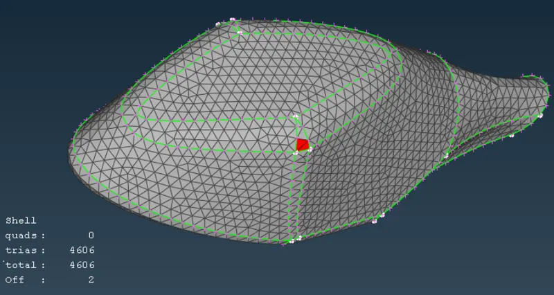
Final after solving issue
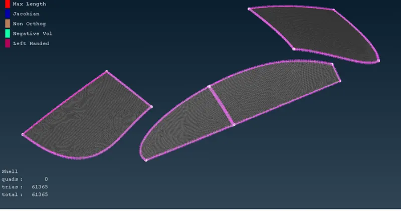
Windows
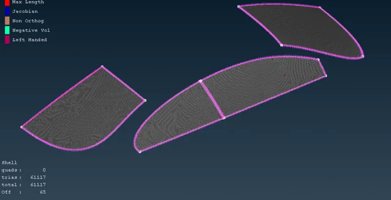
Final
Rims & tyres
Lights
Body:
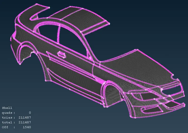
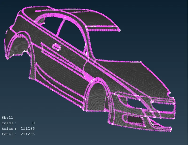
Final half model after meshing
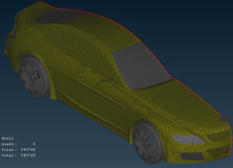
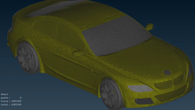
After creating symmetric portion using transform command
Wind Tunnel:
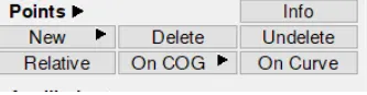
To create Wind tunnel, first reference points are required to create where wind tunnel surfaces will take shape. New points have been created using the "Relative" command available in Point toolbar in TOPO deck. Relative command creates new points with reference to existing reference point.
From the reference point, which is considered as hot points in the floor, the dimensions of the vehicle has been measured to add into the wind tunnel dimensions. The below table shows these dimensions.
From Reference Point
Car Front 650 mm
Car Backside 600 mm
Car Rightside & Leftside 230 mm
The wind tunnel size has been considered as per below table.
Wind Tunnel Dimensions
Car Length (x) 1300 mm
Front 4x + Car Front
Rear 6x + Car Back side
Top 3x from Roof hot point
Bottom 75mm from Car bottom safety cover
Right & Left Side 1x
First, points for the bottom surface & four corners of the wind tunnel has been created. The bottom face has been created just some distance below the tyres to study the aerodynamics characteristics under the floor. Following is the Relative point dialogue box. In the Relative dialogue box, the direction has been inserted using the "1" in case of positive axis direction or by "-1" in case of negative axis direction.
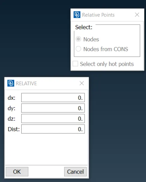
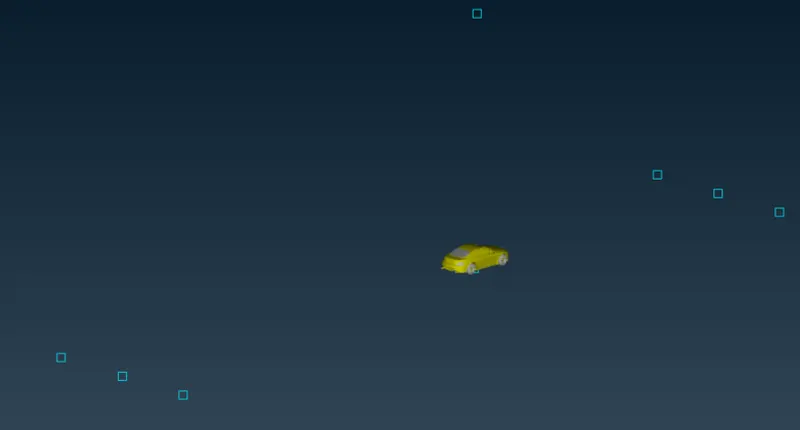
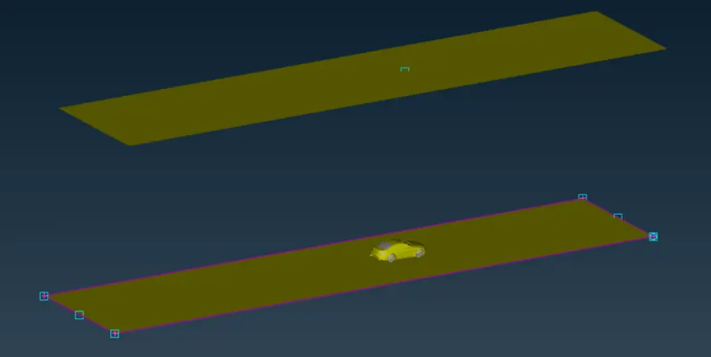
Below image shows the reffernce point created by above method
The rectangle shown has been created using CREAT command available in curves command
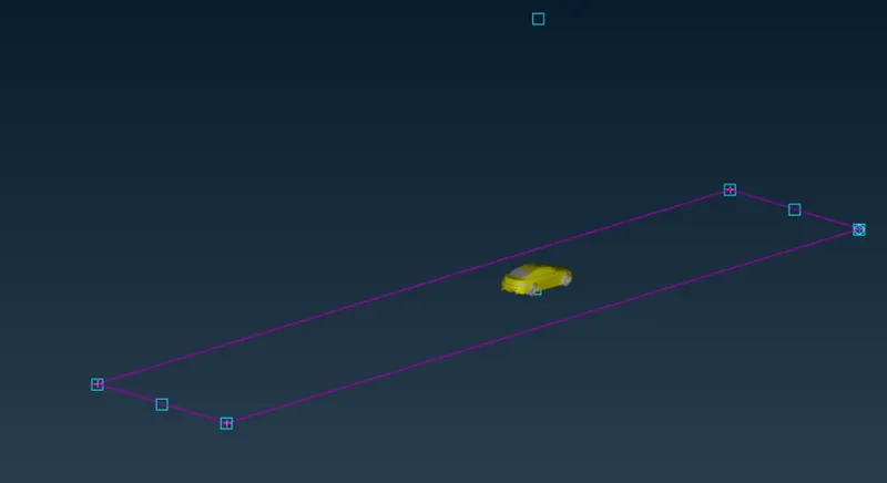
The new face has been created using NEW faces command. and Top surface has been created using offset command
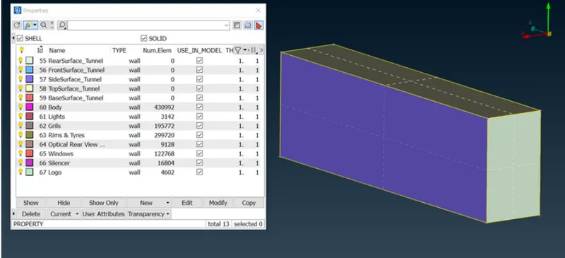
The rest of the side. front and rear surface Has been created Using new face command. And respective PID was also created
Wind Tunnel Meshing:
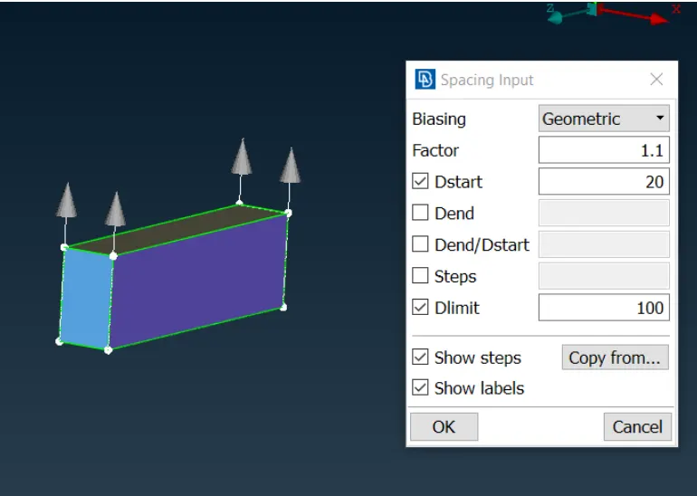
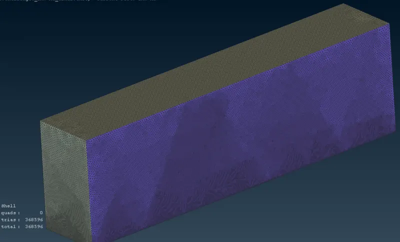
To create meshing, the top & bottom surfaces has been given element length of 100mm & 20mm respectively. All side edges needs to be divided into "Spacing" command to create elements with increasing size from 20mm to 100mm to accommodate between bottom & top surfaces respectively. The "Spacing" command is available in Perimeters toolbar.
Final surface meshing of wind tunnel
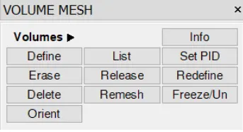
To create volume mesh, single volume between wind tunnel & outside surface of the car is required to form & all the other volumes is needed to be deleted. Using "Define" command in Volume toolbar in Volume mesh deck has been used to detect the number of independent volumes present in the model.
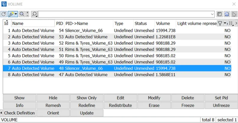
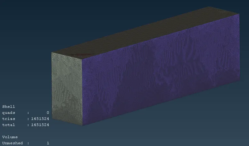
Out of these 8 internal volumes, only one is useful to make the wind tunnel which is mentioned under Auto Detected Volume (2nd from top) & the rest has been deleted. To generate the volume mesh, the required computaion power is very high and because of that the volume mesh has not been performed. Below image shows the wind tunnel with One unmeshed volume.
Geometry model
https://drive.google.com/file/d/1g7_va41wjSBvcRX9VhQDVYN0w_D_ter5/view?usp=sharing
CONCLUSION
• Working on BMW model gave ideas about different meshing tools available in ANSA.
• Learned surface meshing and Geometry cleanup in much detailed manner. Challenges faced helped to understand tools better
• Learned how to use curve tool, how to create win tunnel with help of points and curves
• Learned about dimensions of wind tunnel, like what dimesnions to give based on model size
• Learned how to de meshing when there are different PIDs with different mesh length in contact with each other
• Advance topo-cleanup