Week 4 Challenge : CFD Meshing for BMW car
WEEK 4 CHALLENGE : CFD MESHING FOR BMW CAR
AIM:
1. To check and solve all geometrical errors on half portion.
2. To assign appropriate PIDs.
3. To perform meshing with the given target length and element quality criteria using tria elements only.
4. Target lengths for the different parts of a model are as follow:
- Body - 3 mm
- Lights - 4 mm
- Grills - 1 mm
- Rims and Tyres - 2 mm
- Optical Rear view mirror - 2 mm
- Window - 2 mm
- Silencer - 3 mm
- Logo - 1 mm
5. To do symmetry to the other side after meshing the half model.
6. To create the enclosure for the geometry (wind tunnel) around it.
7. To surface mesh the Wind tunnel surfaces with zero off elements using tria elements only.
8. To write a detailed report of the challenge.
PROCEDURE:
1. Patch the missed surfaces:
- First we need to import the geometry model from the source folder.
- The geometry file contains lot of ir-regularities, discontnuities, so we need to patch all the missing and open surfaces in the geometry.
- This can be done by the following procedure;
TOPO → faces → new → here we can select any method → select the cons (this can be done by entity or PID method) → middle click or surface click.
2. Removing overlapped surfaces:
- At some areas of the geometry, we need to clear the overlapped surfaces.
- This can be done by following procedure;
TOPO → delete → select the surface to be deleted by using entity or PID mode.
- Sometimes we need to project the cons to make the single cons into triple cons.
- This can be done by the following procedure;
TOPO → cons → project → select the cons → middle click → select the face where the cons has to be projected → middle click.
3. PID assigning:
- Now we need to create PID (Property ID) for all the surfaces like inlet, outlet, spring, column, base and valve head.
- This can be done by the following procedure;
Properties → right click on the properties screen → new → PSHELL → PSHELL → box pops-up → name has to be given.
- Similarly we need to create as many as required.
- Now we need to assign the created PID 's to the respective surfaces required and we need to make sure that cross-hatches option is enabled.
- This can be done by the following procedure;
Properties → right click on the PID → apply → select the cross hatch present in the surface of the geometry → middle click on the mouse.
- Similarly we need to do for all the required surfaces.
4. Surface mesh process:
- Now we need to mesh the geometry.
- This can be done in two ways;
- Meshing the whole geometry in one shot. (only with single element length can be done at a time)
- Meshing the geometry part by part individually. (each part or component can be given different element length)
- The first method is employed in this challenge, however the second is highly beneficial when meshing distinct pieces with varying target lengths.
- Messhing can be done by following procedure;
MESH (right side on the screen) → perimeters → length → perimeters → give the target length → ok.
MESH (right side on the screen) → perimeters → length → macros → give the target length → ok.
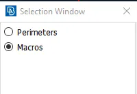
Mesh parameters (Top of the screen) → give the target length, min and max length in that dialog box.
Quality criteria (Top of the screen) → give the target length, min and max length in that dialog box.

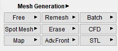
Mesh generation (right side on the screen) → spot mesh → select the geometry to be meshed.
5. Symmetry to other side:
- Now we need to do symmetry to the half meshed model.
- After creating the othe half, at some places single cons may appear, we can clear those by using paste option.
- This can be done by following procedure.
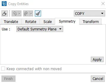
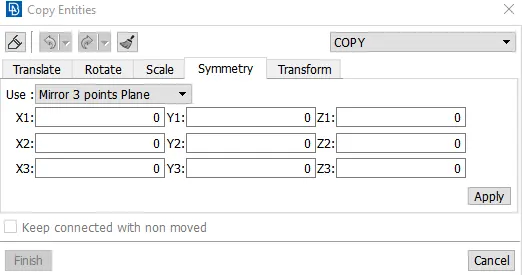
Transform → copy → entities → middle click → symmetry → use → mirror 3 points plane → select 3 points on the geometry
→  →
→ 
6. Enclosure construction:
- Now we need to create a enclosure to the geometry which can aslo be called as wind tunnel.
- We need to take the mesurements of the car.
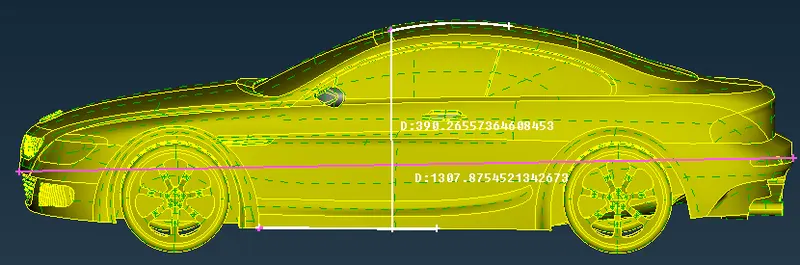
- Now we need to create a point, from that we need to extend our points.
- This can be done by following procedure.
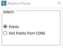
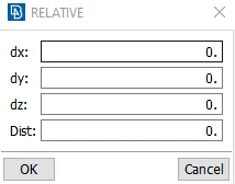
TOPO → points → relative → select the hot point and middle click → specify the direction (- or +) and distance →click ok.
 →
→ 
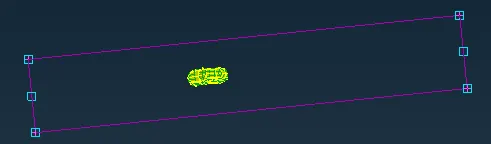
- We need to join the points created using the other tool
TOPO → curves → create → drag from one point to another → middle click → esc.
 →
→ 
- Now we need to create the surface using the other tool.
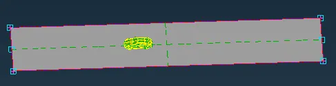
- Now we need to create the similar surface on the top of the car using another tool.
TOPO → faces → offset → select the cons → middle click (arrow appears) → specify the the value.
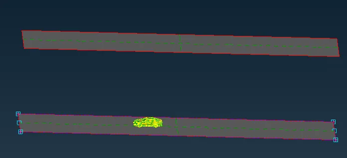
- Now create the faces in the required places using faces tool.
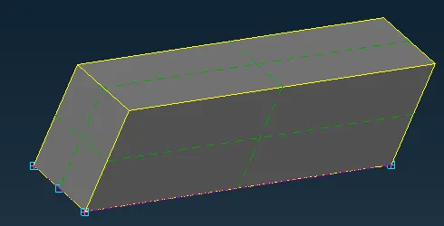
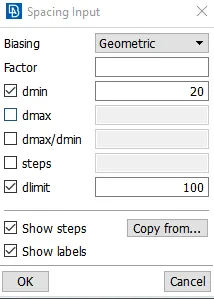
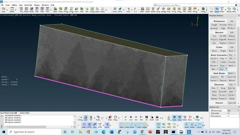
- Now we need to surface mesh the enclosure by 100 mm for the top surface and 20 mm for the bottom surface, for side, top and rear surfaces is meshed from 20-100 mm (bottom to top).
7. Volume identification:
- Here we need to identify the volumes.
volume mesh → volumes → define → auto detect → work on → whole db → ok
- Totally eight volumes have been detected.
- wind tunnel + car → 1
- wheels → 4
- silencers → 2
- car body → 1
- We can keep first one and delete the rest all because it is unnecessary.
Step A: Geometric Cleanup
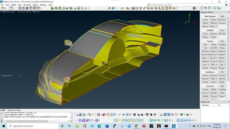
1. The BMW car is symmetric about a plane. Hence to reduce the efforts of geometry cleanup, delete the other half of car. The symmetric plane passes through front hood, roof, rear hood.
2. The front grills have too many openings for the purpose of air circulations. So we have to close these air openings. Hence we need to perform the geometry modification such that the original shape is retained as well as the openings are closed so that a identical volume is formed after performing volume mesh.
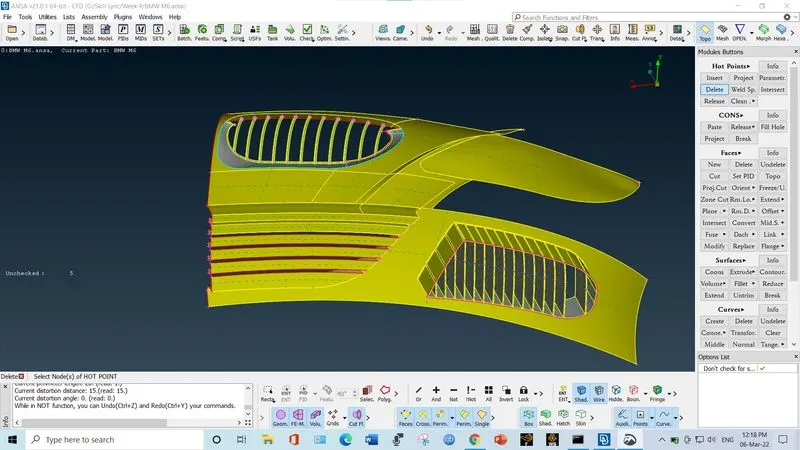
After cleanup, it look like
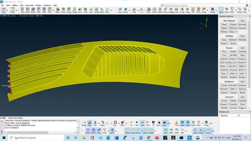
3. Similarly cleanup the area of head lights. Remove the cons of head light inside the car volume. Just keep the cover.
4. Go for removing the triple cons from window, roof, mirror, tyres etc.
5. Delete the additional cons on the roof side and just keep one single continuous surface for roof.
6. Make the floor of car as flat, continuous and uniform as we can. Remove the surfaces from the tyre space.
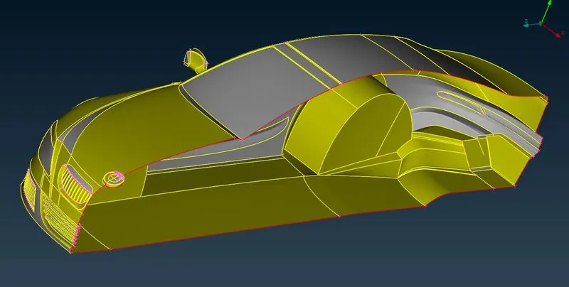
7. Click on Transform from utilities deck. Select copy option. Align the model in top view and make the complete selection using shift key. Select symmetry option and then select 3 point selection plane. And then click on apply.
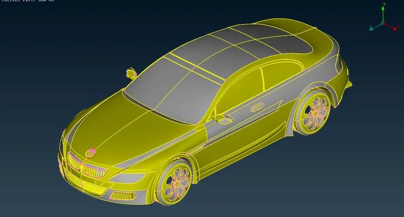
8. Apply PID's for different parts.
# Step B: Apply Surface mesh
1. Grills:
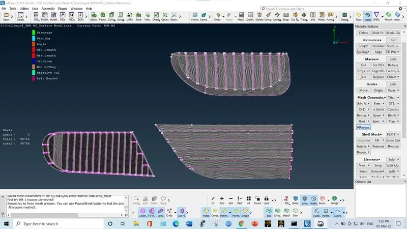
2. Lights
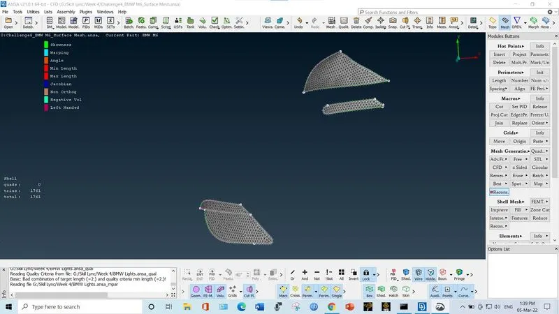
3. Rim and Tyre
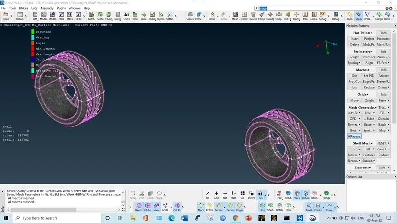
4. Mirror
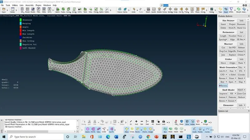
5. Logo
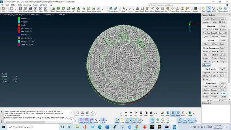
6. Complete Body assembly
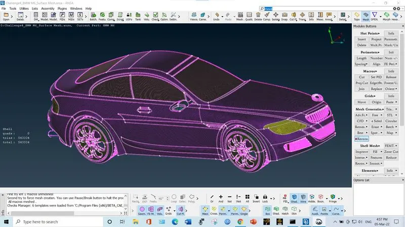
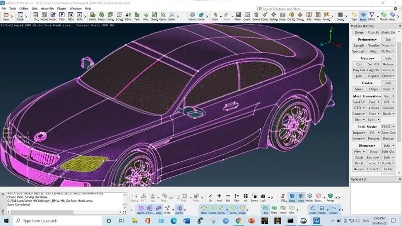
# Step C: Creating the wind tunnel
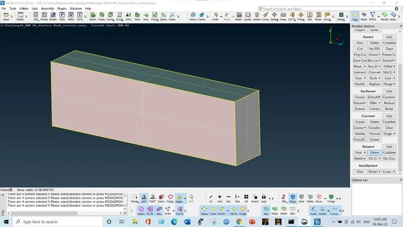
1. Use the option Insert Points and insert the nodes from reference nodes on the surface. Let the length of car be 'X' m. Then the entrance face of wind tunnel is at a distance 4*X from car, exit face is at distance 6*X from car. The top side is at distance 3*X from car. The left and right sides are at distance 1*X from car. (X=1308).
2. Create the surface for the base and then use the option offset to create the top surface. Then use coons option to create front, back, left and right faces.
3. The top side element length is 100. The bottom side element length is 20. Use the option "Spacing" in paramter. Select geometry type. Enter dmin as 20 and dlmt as 100 and select the 4 vertical cons of winf tunnel.
4. Apply the spot mesh on wind tunnel
# Step D: Volume mesh
1. Go to volumes. Select Define. Click on Auto Detect.
2. There will be 7 auto detected volumes shown by ansa.
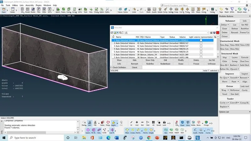
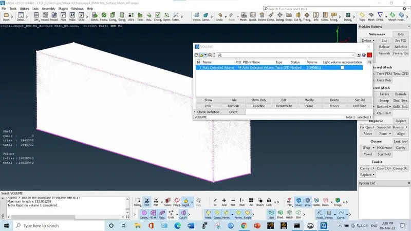
2. Out of these 7, 1st volume is the volume of wind tunnel outside the car body. This volume is our analysis region. Delete the rest of the volumes. Apply the Tetra CFD mesh to the remaining volume.
3.
Conclusion
The surface mesh was generated on the car body and on the wind tunnel surface with the set mesh quality criteria and mesh target lengths.
ANSA FILE: https://drive.google.com/file/d/11gdPj_GajUEQCrZsotccSiopDTkUNReS/view?usp=sharing