Week 4 Challenge : CFD Meshing for BMW car
Aim: For the given model, check and solve all geometrical errors on half portion and Assign appropriate PIDs. Perform meshing with the given Target length and element Quality criteria. After meshing the half model, Do symmetry to the other side.
- Objective:
- Target lengths for the different parts of a model are as follow:
- Body - 3 mm
- Lights - 4 mm
- Grills - 1 mm
- Rims and Tyres - 2 mm
- Optical Rear view mirror - 2 mm
- Window - 2 mm
- Silencer - 3 mm
- Logo - 1 mm
- Model: BMW M6
The initial geometrical model
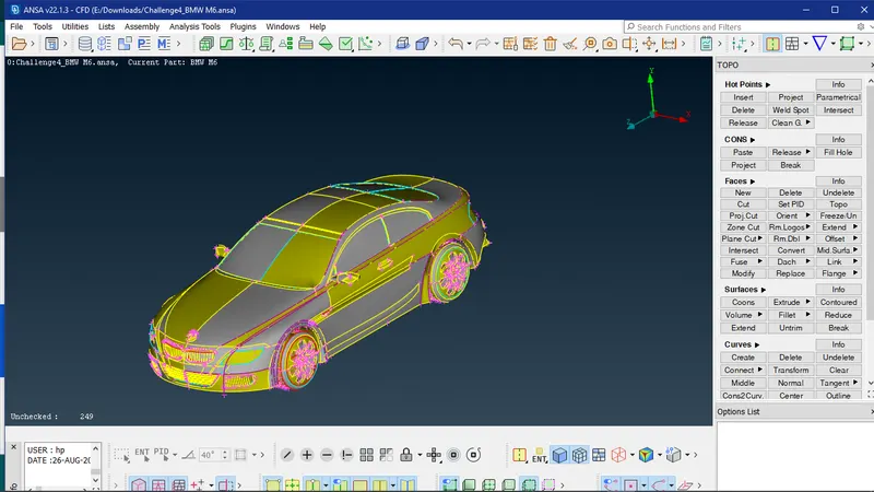
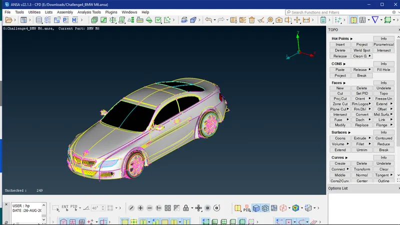
The view of the geometry in PID mode
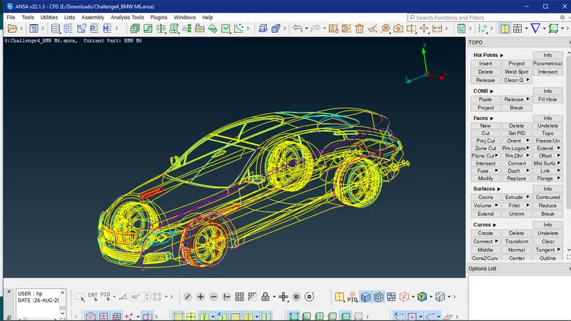
While viewing the geometry in wireframe view it can be seen that some single CONS are present and they need to be converted to double and triple CONS using TOPO option.
Selecting the complete geometry to perform topology
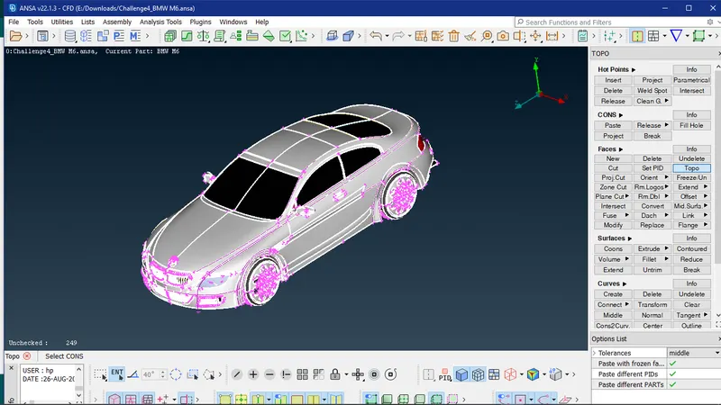
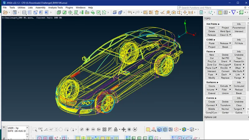
The model after performing topology operation
Some double and triple cons have been created
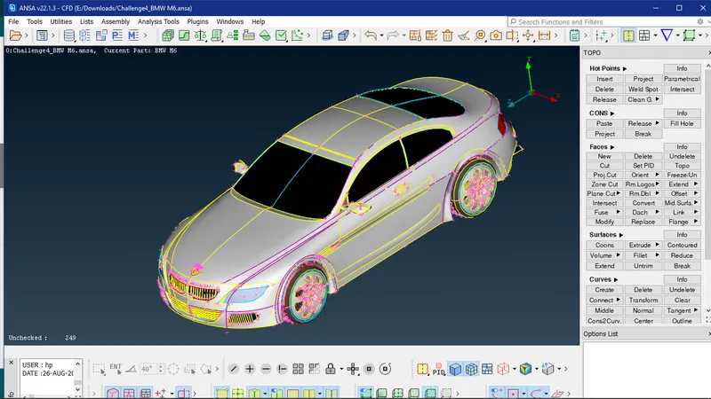
Now the geometrical model should be checked for errors in order to rectify them
To improve the resolution of the CONS use the fine option in the auxiliaries section
By clicking multiple times on a single surface part the surface can be corrected to the desired shape
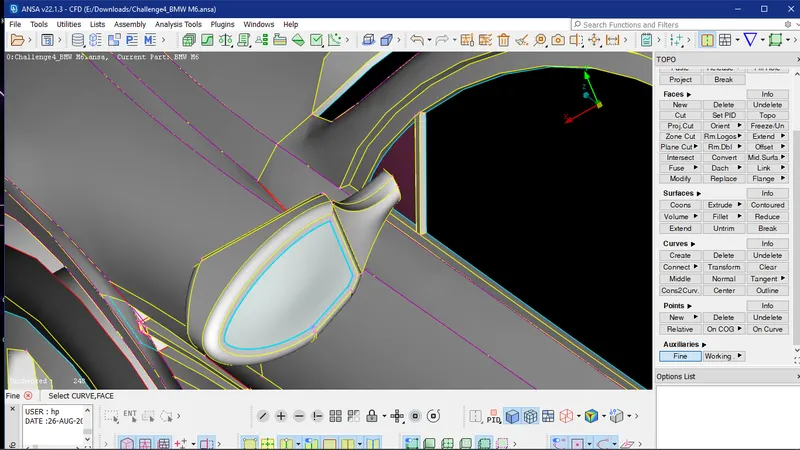
However this approach is not desirable as it is too much time consuming.
So an alternative approach is by using the mesh mode
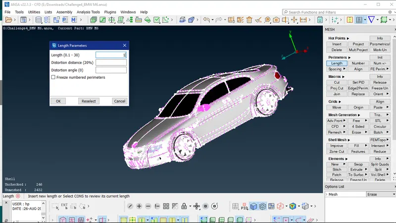
Specifying the length in the perimeter section as 1mm.
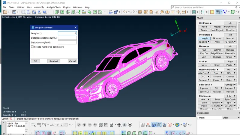
Specifying macros as 1mm
After performing this operation and selecting TOPO mode it can be seen that the geometry has somewhat smooth surfaces and looks refined
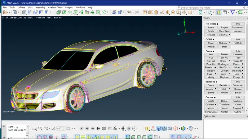
Since this model is symmetrical any operations performed on one side can be reflected on the other half. So all required operations can be performed on any one side of the geometry. As we are going to perform symmetry any one half portion of the geometry can be deleted.
Selection of half portion of geometry
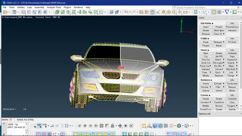
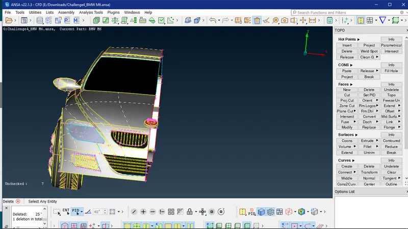
Deleting the unwanted surfaces on the inner side
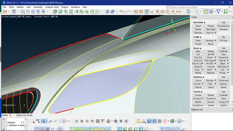
Using cut and then deleting the surfaces
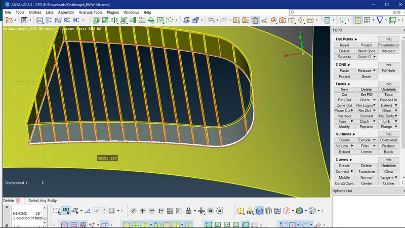
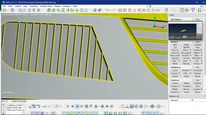
Fixing the logo geometry
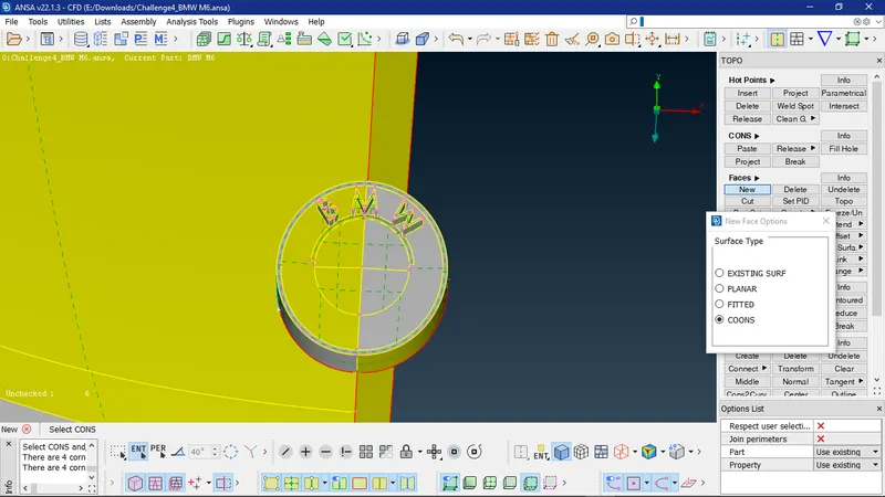
Correcting the windshield geometry
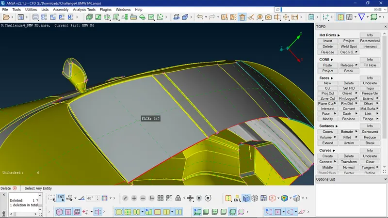
Fixing the window geometry by deleting the inner thickness
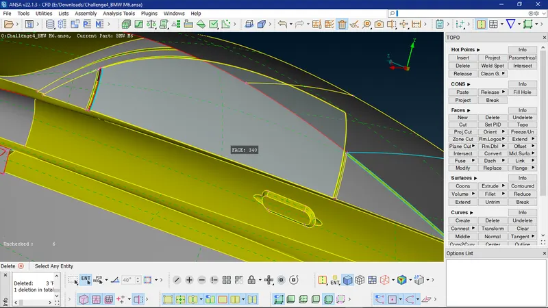
Fixing the rear windshield geometry
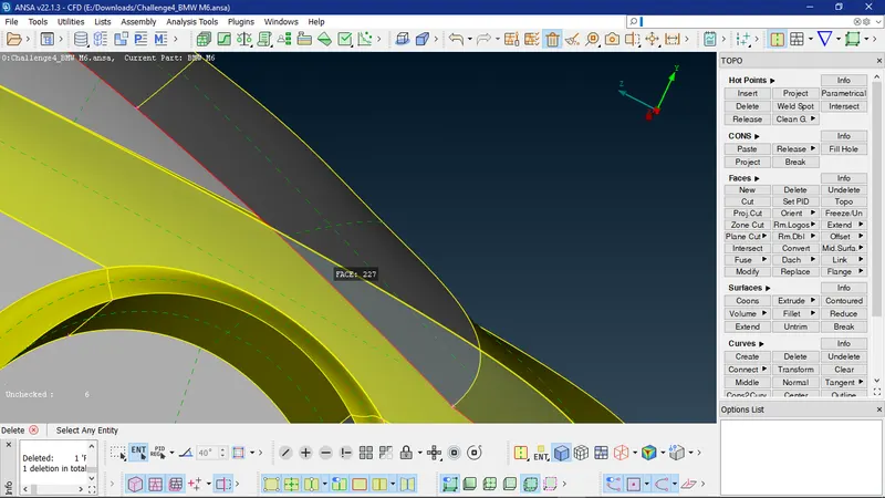
Correcting the rear tail lamps
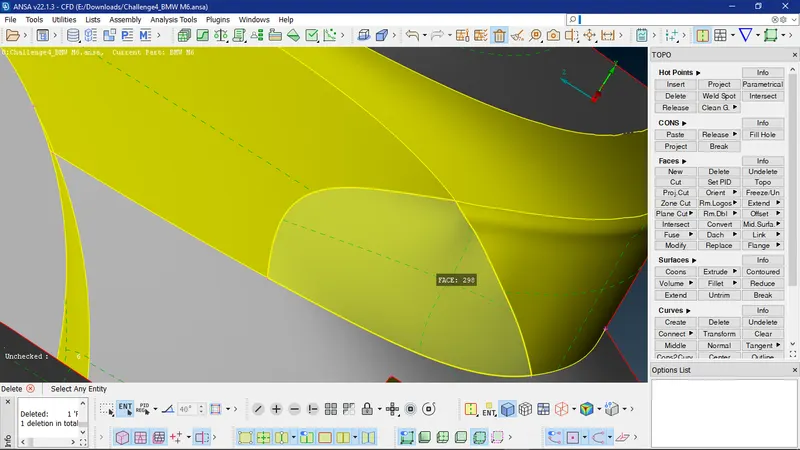
Creating project cuts to fix the front portion
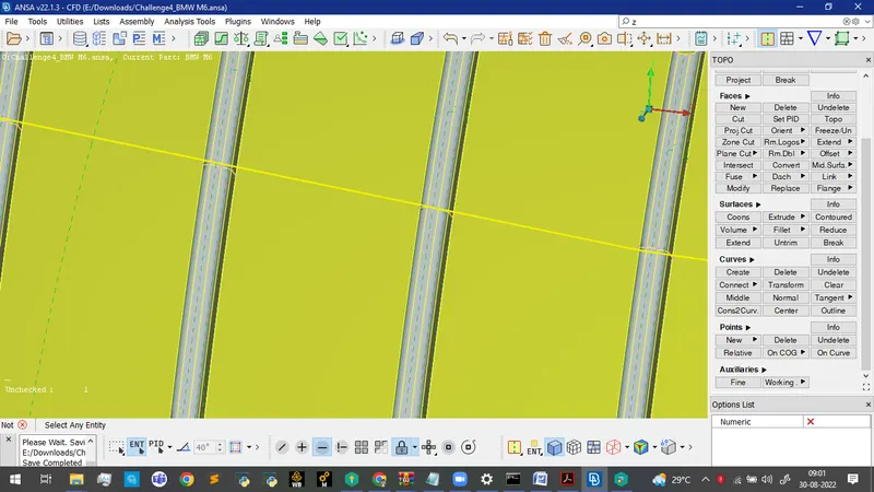
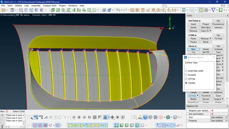
- Design feature and mirror:
a. Perform topo and identify the triple and single cons, and delete the extra unwanted surface to maintain a common volume.
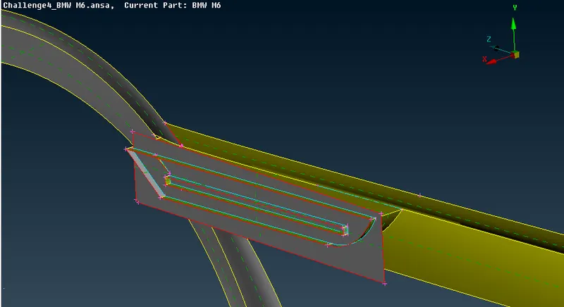
b. Use the intersect option to identify the triple cons at the intersection area and can delete the smaller surfaces individually.
c. Extended the single cons on the adjacent surface to create triple cons and delete the unwanted surfaces by doing that.
d. Delete and re-create surfaces accordingly to have a smooth and perfect shape at tight corners. Also uncut the lines which are necessary which might cause trouble during meshing.
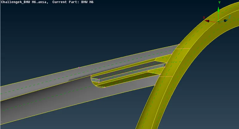
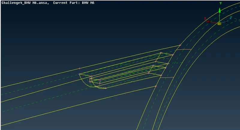
e. Isolate the mirror and perform topo clean-up, hide the surfaces blocking the the triple cons view.
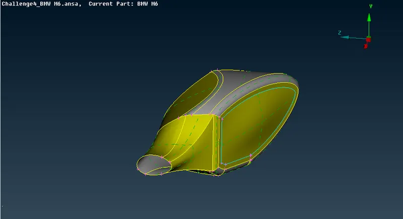
f. Delete the extra surfaces and create a single volume, also at the car and mirror connection region perform extend on the car surface and create a single volume by deleting the extra surfaces.
- Wheel and Base region:
a. Isolate the wheels to perform geometry clean-up, to rectify the triple cons, hide the surface blocking the view and delete the overlappng surfaces causing triple cons.
b. Create larger surfaces after deleting smaller surfaces which are parallel to each other.
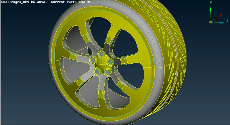
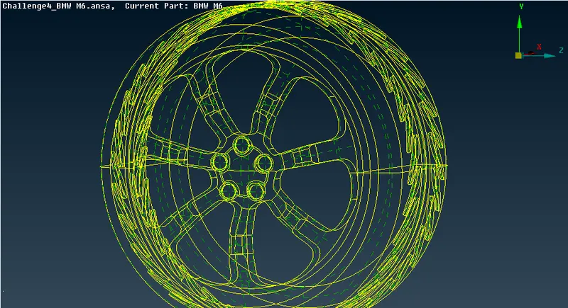
c. The base of the car is intersecting with the tyre, therefore we need to delete the excess surface and also delete the extra design surfaces which cause smaller edges, this causes problems while creating mesh.
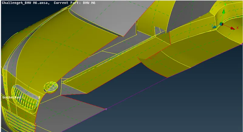
fig 16: Using curve feature while topo clean-up
d. Therefore we need to clean the entire base and create new surfaces accordingly having smooth edges.
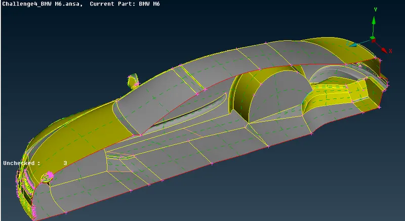
fig 17: Base geometry clean-up
e. After making the surface changes, we need to check if the base surfaces has no intersection with the tyre region.
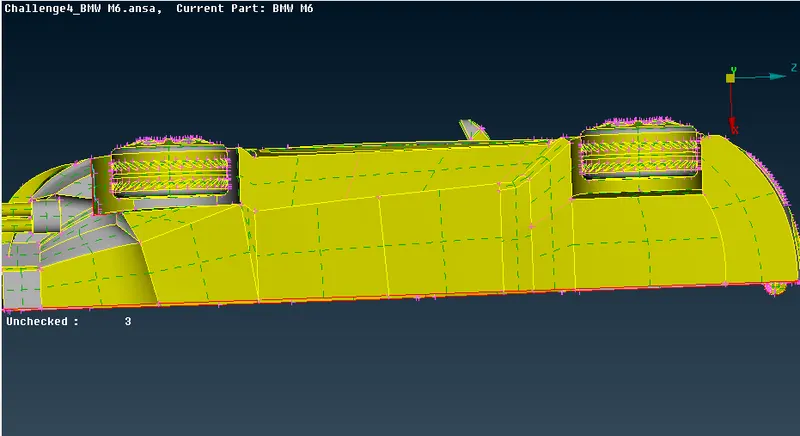
fig 18: checking interference between tyre and body
- After checking and performing topo-clean up for the entire half car model. We need to perform geometry checks to find small cracks are unchecked faces extra which is not good for the geometry, therefore we need to perform checks and clean the geometry accordingly.
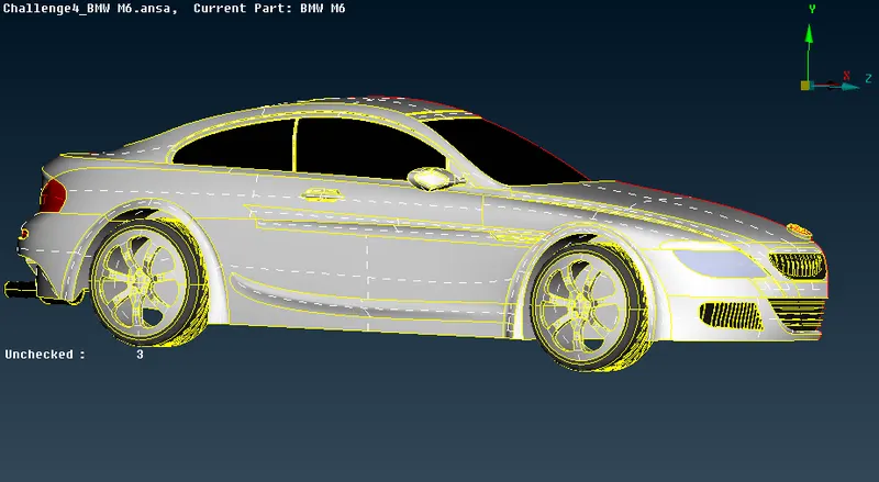
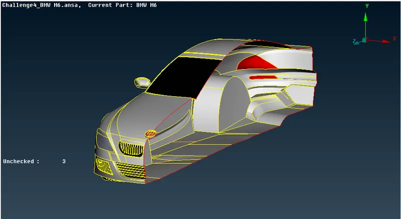
fig 19 a,b: Checking for geometry checks
- Once the geometry is checked and has no errors, we can now assign names to different components using PID.
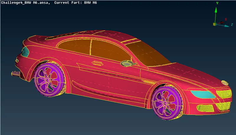
fig 20: Assigned PID regions
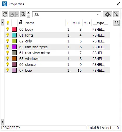
fig 21: PID table
- After assigning the names, we now to choose the quality criteria method. Choose openFOAM solver next to volumetric mesh and choose the given quality criteria below.
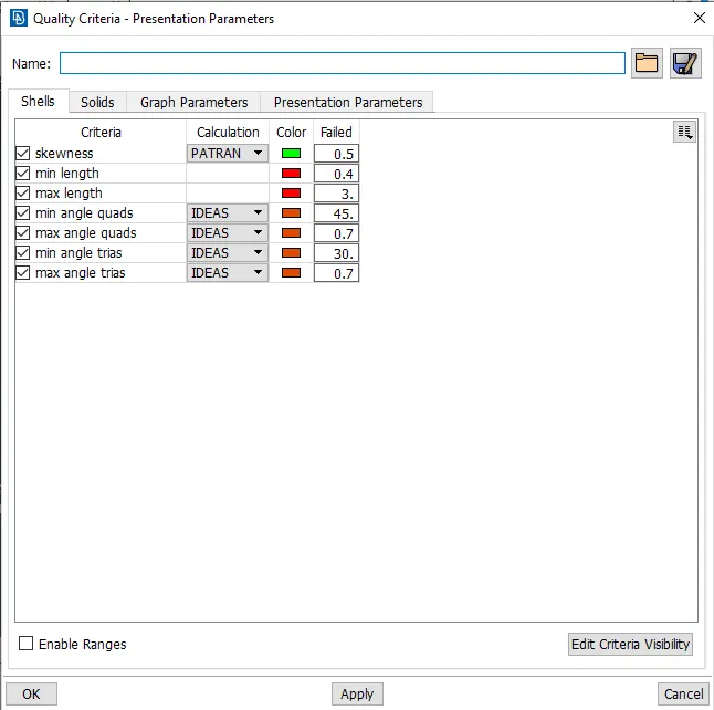
fig 22: Quality criteria table
- Using the measure tool we can calcualte the smallest distance between to cons or hot points and depending on that, we can assign our minimum and maximum length accordingly in the mesh parameters, if we do not do this we can get failed mesh.
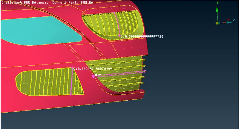
fig 23: Using measure tool
2. Surface meshing:
We need to mesh the components individually since the given mesh targets are different for each PID regions.
Assign the mesh parameters and quality parameters for each PID accordingly, assigning the correct min and max length will reduce mesh failure and off elements.
- Quality criteria for logo and grills region:
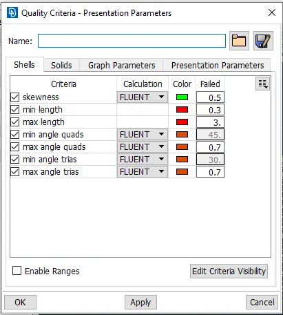
- Logo and grill surface mesh:
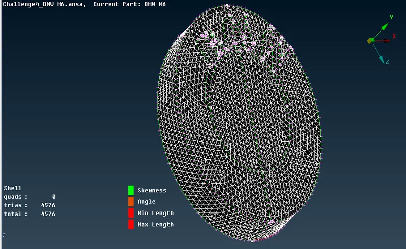
fig 24: Logo surface mesh
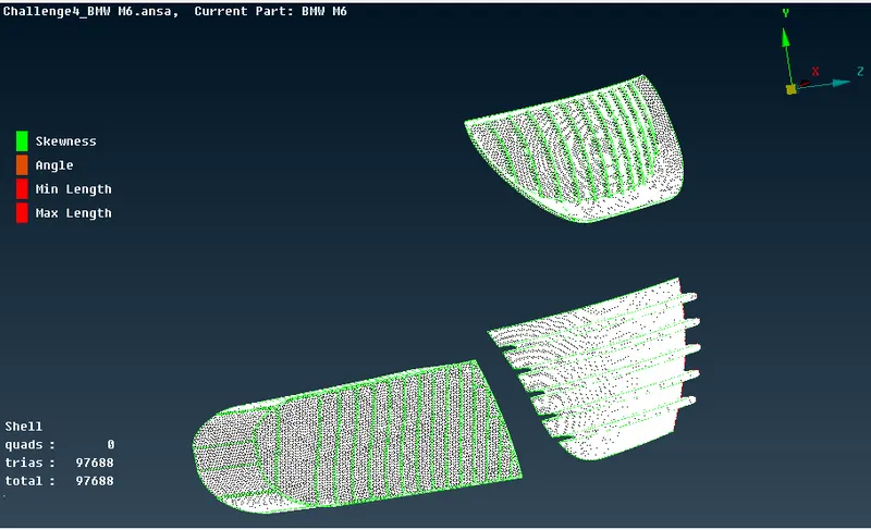
fig 25: Grills surface mesh
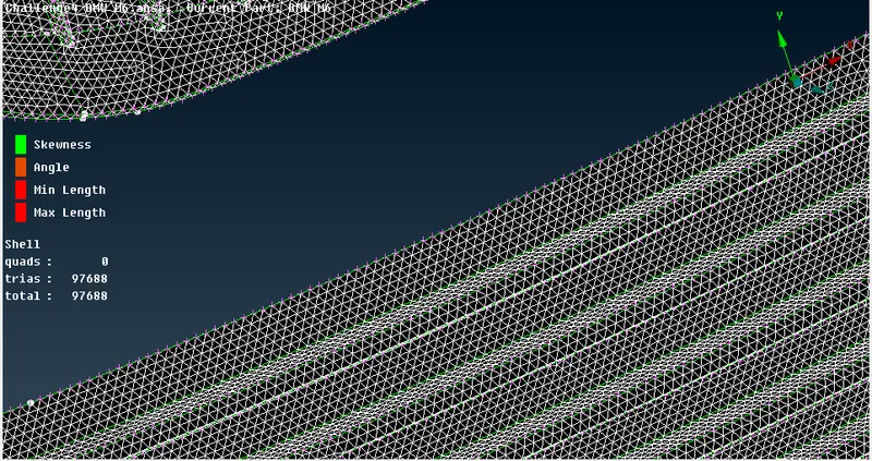
fig 26: grill surface mesh close view
- Rims and tyres, window and rear view mirror surface mesh:
- Quality criteria and mesh parameters:
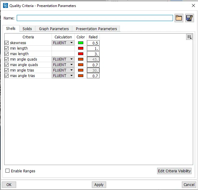
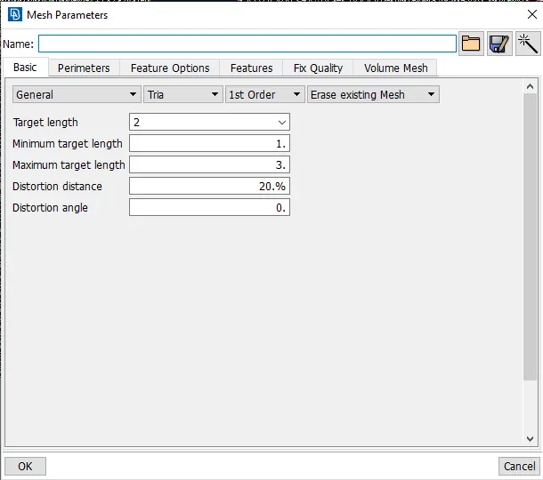
- Surface mesh:
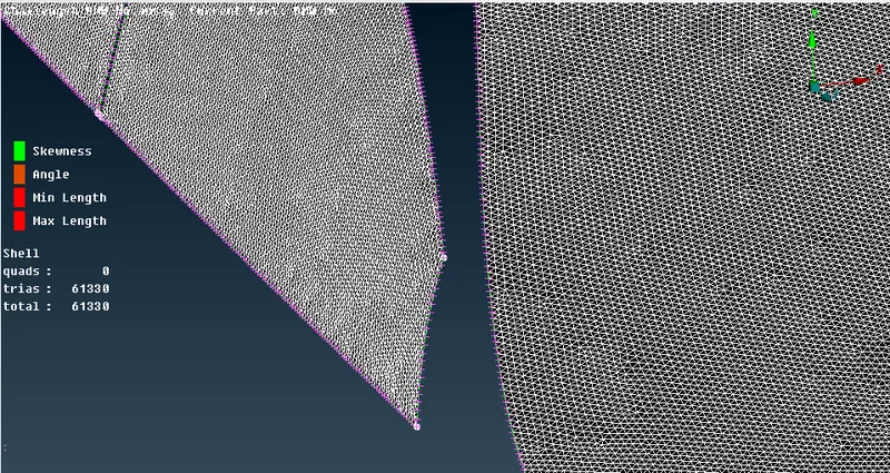
fig 27: surface mesh of windows
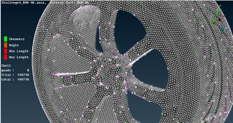
fig 28: surface mesh of tyre
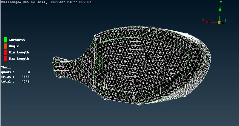
fig 29: surface mesh on Rear view mirror
- Silencer and lights:
- Quality criteria and mesh parameters for silencer:
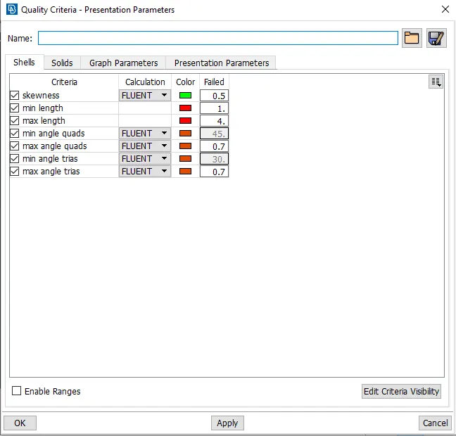
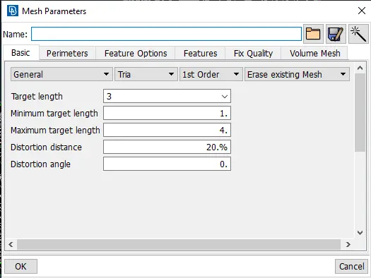
- Surface mesh:
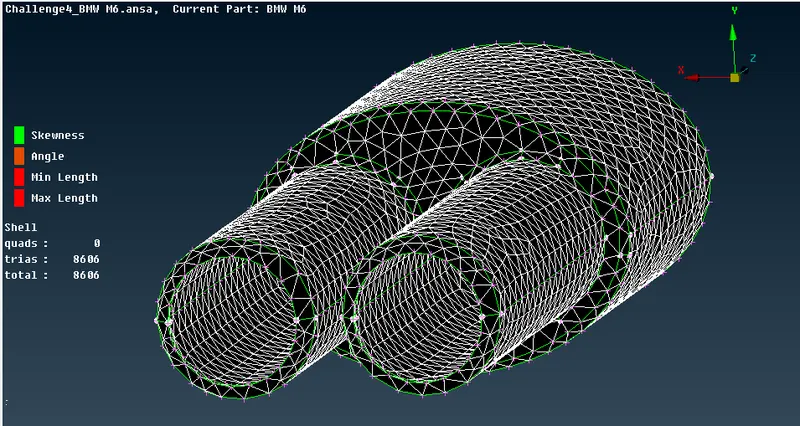
fig 30: surface mesh on silencer
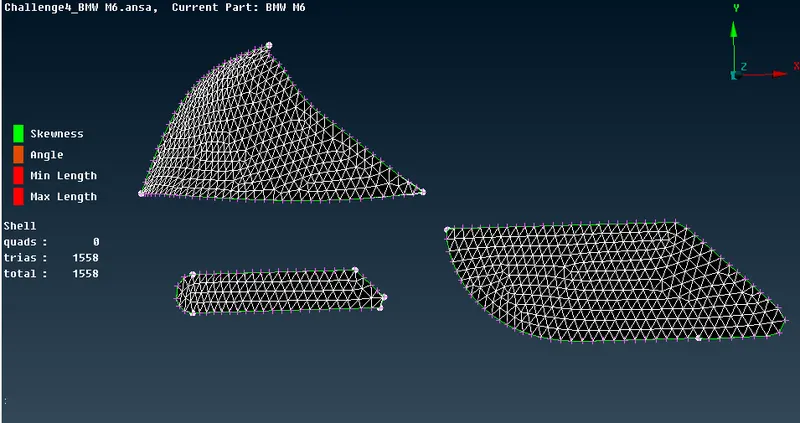
fig 31: Surface mesh on lights
- Body surface mesh:
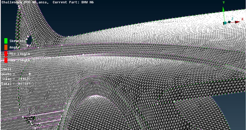
fig 32: Car body surface mesh
Since body PID region is in contact with various other PID, the mesh length variation at the boundary region of 2 different PID cause the mesh to erase or cause mesh failure. Therefore, While entering the perimeters under length in mesh drop down. Select the regions which are not in contact with the other meshed PID regions. This helps in avoided the mesh to be erased and can later be edited to erase the off elements.
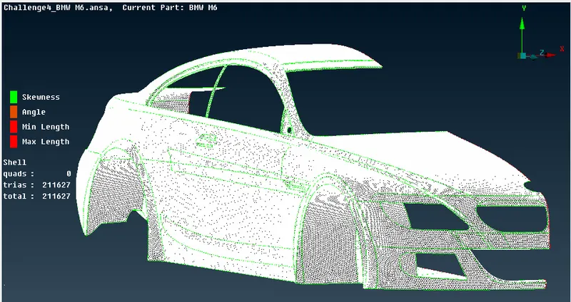
fig 33: Checking for off elements in entity mode of car body
After meshing, we can choose re-construct under shell mesh to reduce the off elements. And later the remaining off elements can be edited manually.
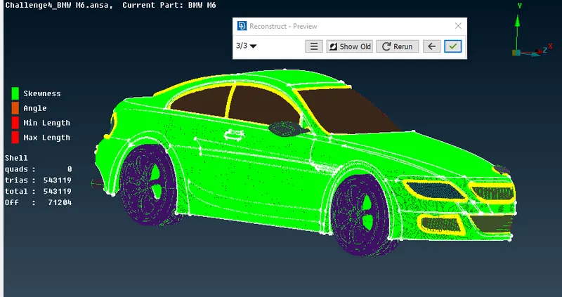
fig 34: Using re-construct option to reduce off elements
- Final surface mesh of car model:
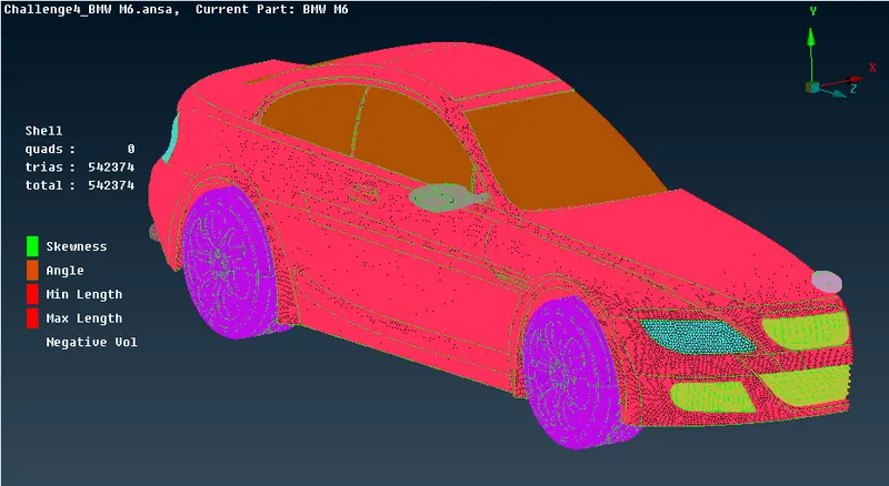
fig 35: Complete car model with 0 off elements
- Performing symmetry on the car model:
a. Perform symmetry under transform option to create a exact same opposite body of the car to create a full body car.
b. Use the copy option and select the half body car and diselect the logo sice we dont need a copy of the logo.
c. After choosing the model, middle click mouse, we get a window, choose symmetry and choose mirror 3 points plane and choose 3 points on the edge to be performed symmetry.
d. After choosing 3 points, middle click twice and the symmetry is performed, click middle click again to confirm the geometry and complete the process.
e. There will be few single cons present near the middle section, use paste or other tools to solve the probem.
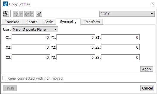
fig 36: Symmetry conditions window
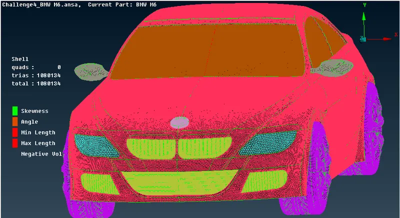
fig 37: Surface mesh on full car body after performing symmetry
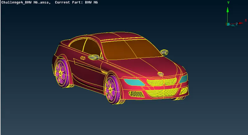
fig 38: Final car model
- Creating wind tunnel:
a. First, we need to create reference points to create wind tunnel surfaces.
b. Select relative under points in topo mode, create a point below the car taking one reference point and entering the correct values.
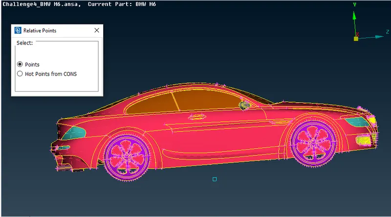
fig 39: Using relative points tool
c. And calculating the wind tunnel dimensions appropriately, we can create the wind tunnel accurately.
d. The wind tunnel dimmensions are: ( standard distance of the tunnel wrt to car model)
car model: 1306mm .................. (x)
Front surface distance(from reference points): 5875mm .................. (4x)
Back surface distance(from reference points): 8480mm .................. (6x)
Top surface distance(from reference points): 4323mm .................. (3x)
e. After creating the bottom surface use the curves for having the reference of cons, we can delete all the hot points and curves.
f. Create all the other wind tunnel surface using the new surface option.
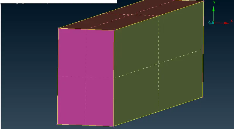
fig 40: Wind tunnel
- Surafce meshing of wind tunnel:
a. We need to apply surface meshing depending the mesh length near the car and regions far away from it.
b. Therefore we need to apply different mesh lengths at the bottom and top wind tunnel surfaces.
c. We need to use spacing option to have a mesh length varying from the small mesh length size to larger mesh length.
d. Surface meshing can be achieved by doing this accordingly.
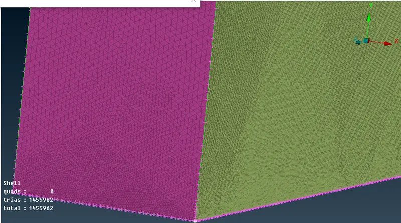
fig 41: Surface mesh of wind tunnel
- Volumetric mesh of wind tunnel-car volume:
a. Since we are interested only the volume between the car model and wind tunnel, we can delete other volumes of the car model which is not necessary.
b. Since performing the volumetric mesh takes 2-3 days, volumetric mesh is not performed as given by the challenge question.
- Volume regions:
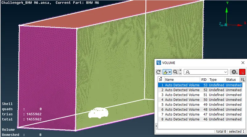
fig 42: Volume between wind tunnel and car model
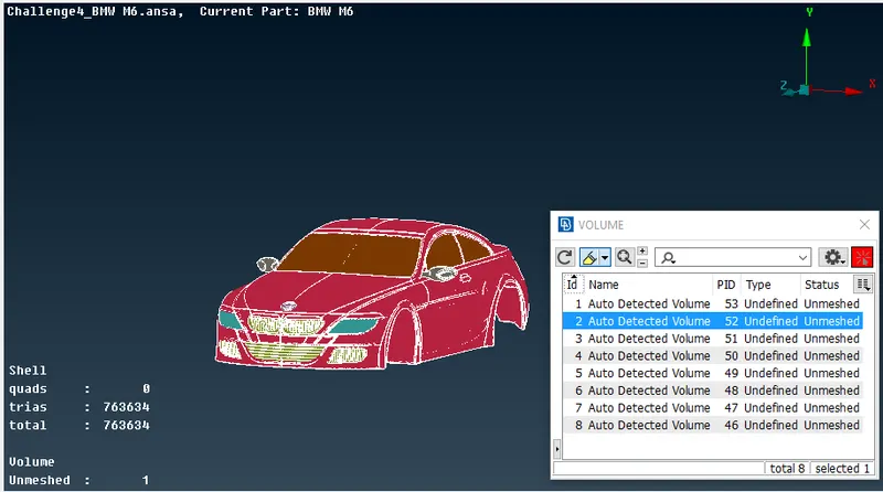
fig 43: Car body single volume
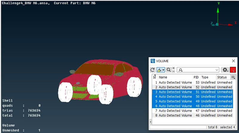
fig 44: Tyres volume
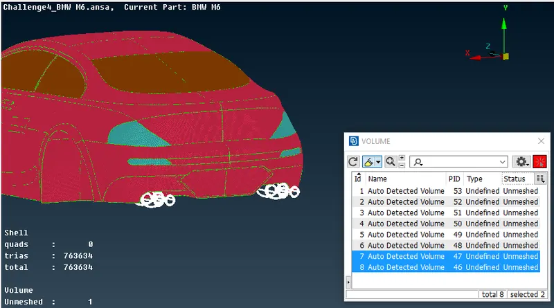
fig 45: Silencer volume
Learning outcomes:
a. Learnt the complete CFD meshing skill from skratch.
b. Performed various topo clean-ups using different tools.
c. Understood the need of double cons and removing unecessary triple and single cons.
d. The use of symmetry helps in reducing the work time and helps in having accurate results with less work.
e. Create surfaces using the reference hot points by using relative points.
f. Surface meshing for different components and their varying mesh lengths.
g. Using spacing option in surface meshing helps in having varying mesh lengths along the surfaces.
h. Using re-construct option to reduce off elements to a level where we can edited it manually.
i. Using the mesh modifying tools like move, split and smooth options.
- Conclusions:
1. BMW car model is topo-cleaned and surface meshed appropriately.
2. Wind tunnel is created and surface meshed with reference to the car model size.
3. Different volumes of the car model is created since th silencer and tyres are not connected to the car body.
4. Single volume is created of the car body so that it can be avoided at one go when creating a volumetric mesh.
5. Required physics tests can be performed on the wind tunnel volume model after volumetric meshing successfully.