Week 4 Challenge
CHALLENGE 4
1.
TOOLING DIRECTION
In Plastic Injection Moulding, we introduce the Molten Plastic into the Mould Cavity using a Injecting Tool. It is as shown in the picture below -
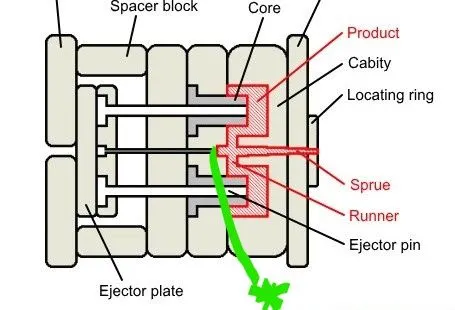
The green marker shows the Injector Tool. As we can see, the tool is introduced into the Mould cavity. So, the direction this tool follows in order to make a satisfactory Injection of Molten plastic into the Mould Cavity is known as the Tooling Direction. Before finalising the Tooling Direction, we usually perform certain tests and simulations to check if the assumed Tooling Direction satisfies the entire area of the part. Tooling Direction is basically an axis or path the Tool follows during the Moulding process.
2.
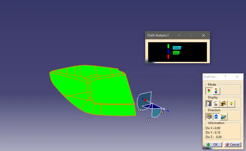
As we can see in the picture below, the blue line shows the Tooling Direction. The simulations and tests we talked in the previous sections are done here. The test is called Draft Analysis. Using this test, we can find out if the Tooling Axis satisfies the entirety of the part. We can give the range within which the Draft should be. This can be seen in the Table in the picture below.
The accepted Upper Draft Limit is 10 Degrees. If the angle lies above 10 Degrees then the part turns Green. (Meaning it satisfies the 10 Degrees Draft)
The second Draft Limit is between 0 Degrees and 10 Degrees. The colour Blue will be shown when the angle is between 0 and 10 Degrees.
The third Draft Limit is below 0 Degress. The colour red is shown in such a situation. This is completely unacceptable, because this means that it creates an Undercut, which is not solvable without using a Side Core.
3.
PARTING LINE
In a Plastic Injection Moulding Machine, we have two halves that complete the machine. It can be seen in the picture below -
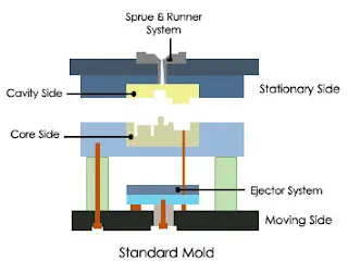
The two halves previously mentioned are called Core and Cavity.
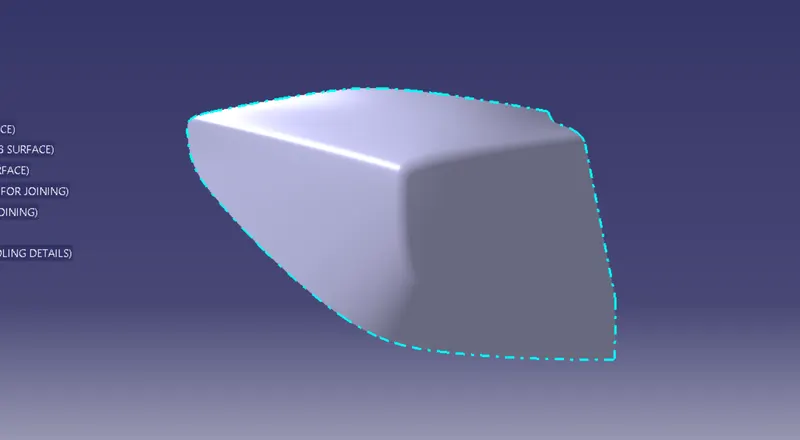
Core makes up the Convex half of the Mould Cavity. Cavity makes up the Concave half of the Mould Cavity. So, these two halves are brought together during the Injection Moulding process. And during this process it is common to see a little spillage of Molten plastic out of the Cavity in the form of a thin line. This spillage through the thin line or gap present between these two halves creates what is known as Parting Line.
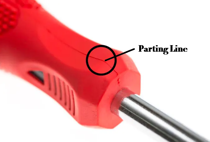
This parting line is formed where both the halves of the Plastic Injection Moulding Machine come together.
4.
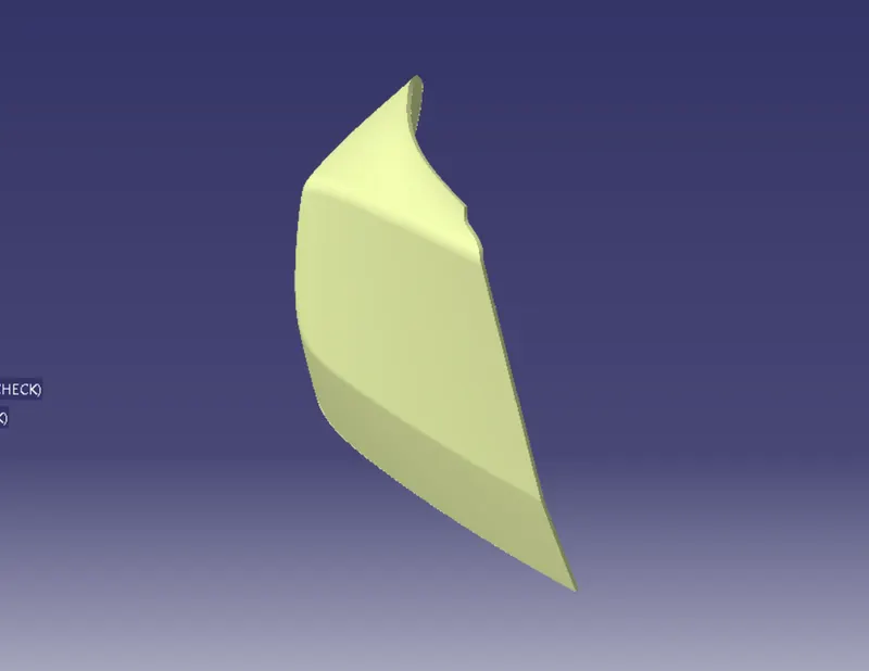
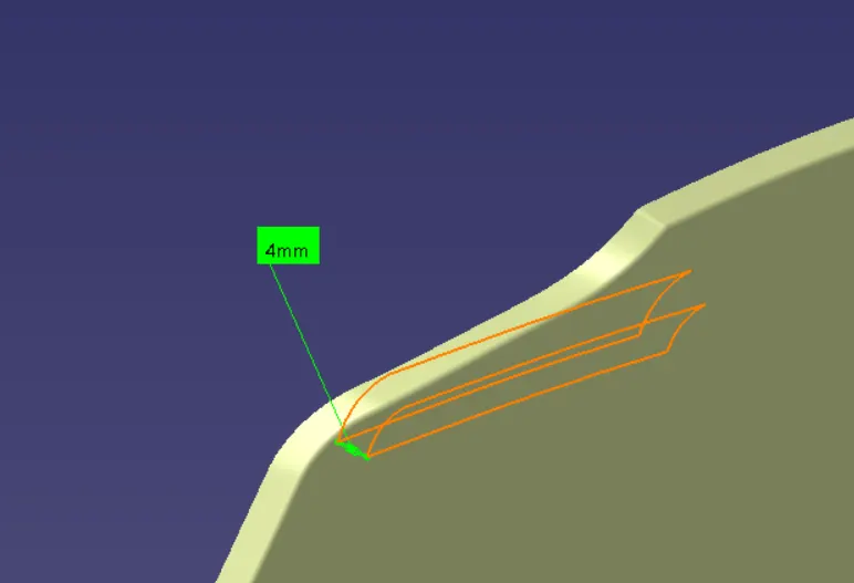
CLASS B SURFACE (Thickness = 4 mm)
5.
PARTING LINE
How-to
- The Design Process starts with the Class A surface provided.
- The first thing to do is to inspect the surface for any irregularities. If any found, we improve the surface using the Surface Workbench.
- After this is done, we offset the surface by the required distance (0.75 mm for Sheet Metal, 4 mm in this case).
- We then go on to build the connecting surface between the Class A and Class B. This connecting surface is built keeping in mind the Draft Angle of the Part.
- Once we build the connecting surface we go on to trim the extra sheet off and join all the surfaces together to make one closed surface.
- This Closed surface is checked for any openings.
- Then a Tooling Axis is created.
- We then perform Draft Analysis on this closed surface. Once it's good to go and there is no need for alterations, we move onto the next step.
- We then proceed to "Closed Surface" command. This creates a thickened part.