Week 4 Challenge
TOOLING DIRECTION : Tooling direction is a process of finding out the maximum clearence of a component by checking all possible directions we can able to find one maximum cleraing direction for any plastic component.
here in this case i am checking the tooling direction for lens class A surface.
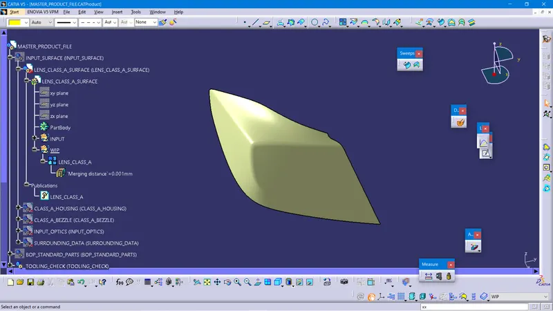
This is the lens classA which i recived from the styling department after reciving of a class A i did some checks on the class A to know about any tangential or point errors are there are not . once i conformed that there are no eorrors found on the class A i will go for the draft analysis to check maximum clearence.
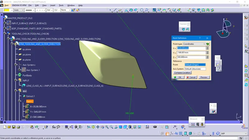
if you want to perform draft analysis on any components class A we need to create few inputs which are required for performing the draft analysis like creating point on the class A and creating axis system on that perticular point.
creation of a point and axis system in catia V5
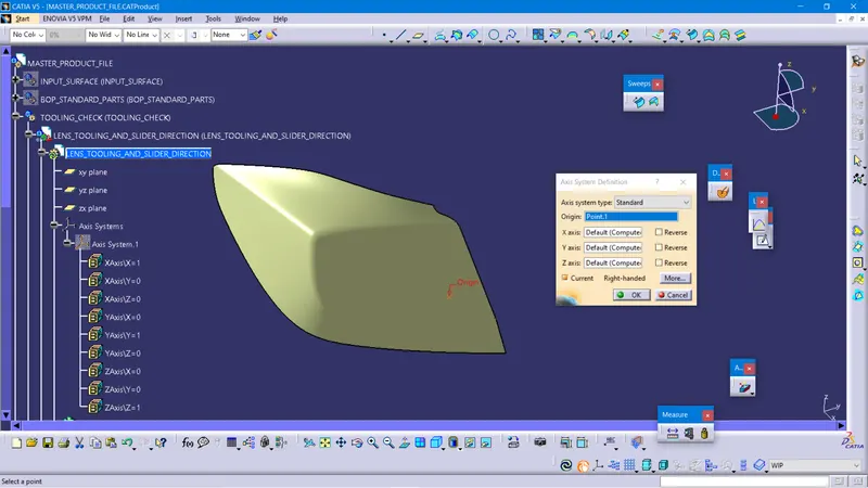
Creating axis system on the point
after creating the axis system i will have to check for the maximum clearence direction here i had assumed one direction for applying trail and error. And after applying multiple trail and erros i found out one best tooling axis with reference to the axis system and the tooling angle is 11 degrees in x direction.
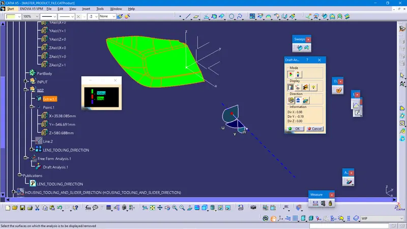
- the surface which was in green colour that angle will be less than 10 degree. And here there are three colours and this three colous indicates three different angle they are green means angle less than 10 degree.
- And red means angle should be between zero and 10 degree.
- Finally blue means the angle will be neagitive .
After knowing the tooling direction i will have to create the B surface for the lens class A
Creating a class B we have to do offset by 4mm towards the inside direction as i shown below
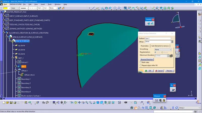
if i am trying to do the offset of 4mm i am getting one patch in the B surface now i have to clear that patch with the tool which are available in GSD . Here i am using the multi section solid to clear that patch because this is only the tool which has multiple advantages so that is why i have selected the multisection tool .
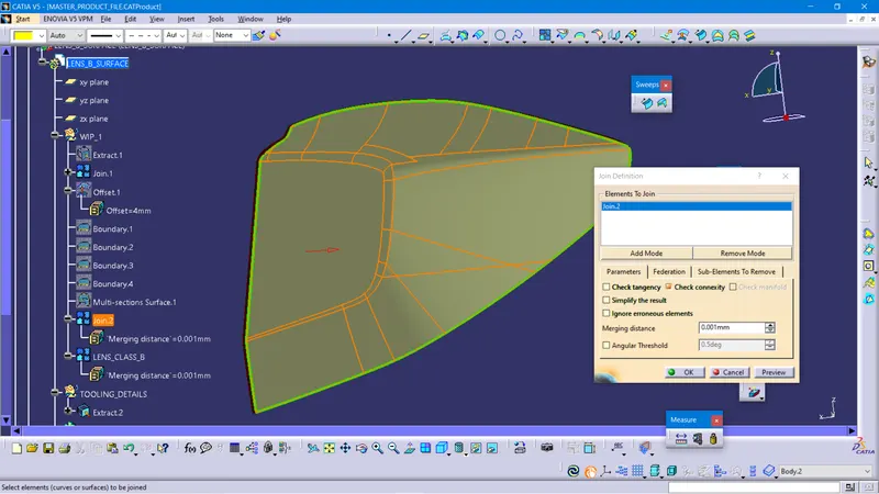
i had clear that patch and joined finally i got class B surface. Now i have to create the close surface to produce the solid out of close surface.
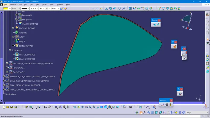
Here i had created the close surface with the help of blend and sweep with the draft direction. now i have to join A,B and C surfaces to gether to produce the close volume solid .
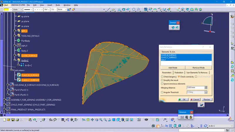
Now i have to create close body with the help of this close volume surface in the part design .
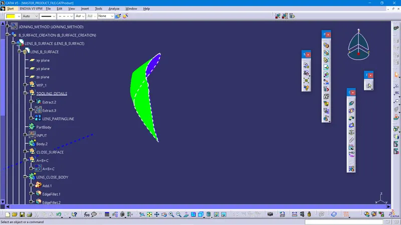
PARTING LINE : Parting line is a line where core and cavity will get separated each other it is called parting line here in lens case the cavity represented in green colour and core will be represented in blue colour those two colours will be obained by draft analysis.
here the white colour doted line will representing the parting line.That is where the core and cavity will gets separated to each other.