Week 4- Challenge
* Objective: To generate mesh and deploy the 1D element on that and also define the cross section to the 1D element and assigining the property to them.
* Procedure:
- Import the "IGES" geometry of the bracket file given.
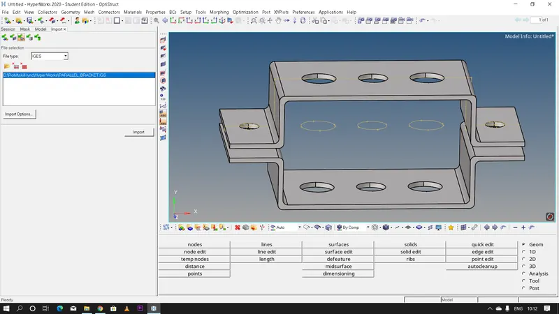
- Let us first extract the midsurface of the given bracket because the bracket has uniform thickness therefore meshing the midsurface and assigning proper thickness value to the midsurface will give us much much lesser nodes and elements than creating a surface mesh or 3D mesh using 'tetra' and 'hexa' elements which inturn leads to more processing time.
- Steps to be followed to extract the midsurface: Geometry >> midsurface >> extraction options >> skin offset (there are several other options also we need to choose the option which gives the best output) >> auto extraction >> select the surfaces >> click extract >> rename it as 'Bracket 1'.
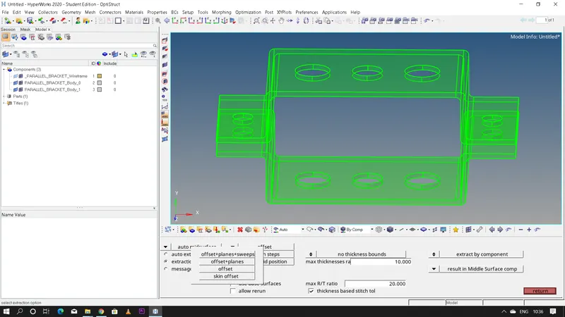

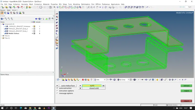
- Before creating the midsurface for the other bracket we need to create a new component and rename it as 'Bracket 2' or else both the midsurfaces will be having same component-id and that is not ideal.After creating both the midsurfaces delete the parent surface since it is not needed anymore.
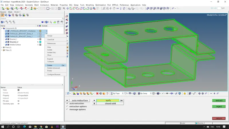
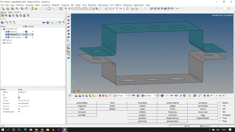
- Now we need to assign the midsurface created to the 'Bracket 2' component which we had created previously.
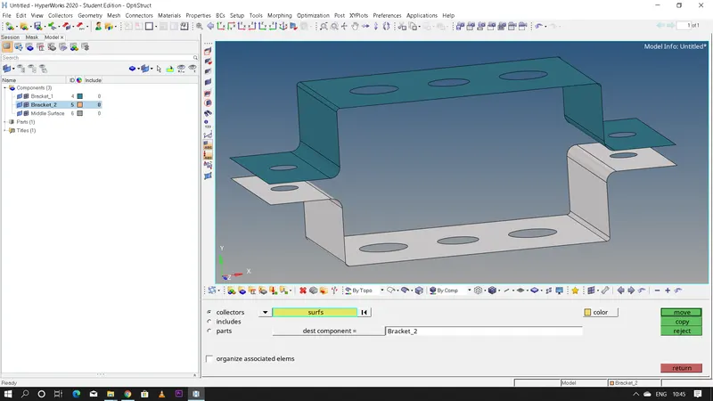
- Steps to organize the midsurface to the component: Tool >> organize >> make sure that the current component is 'Bracket 2' >> select the midsurface >> click on move.
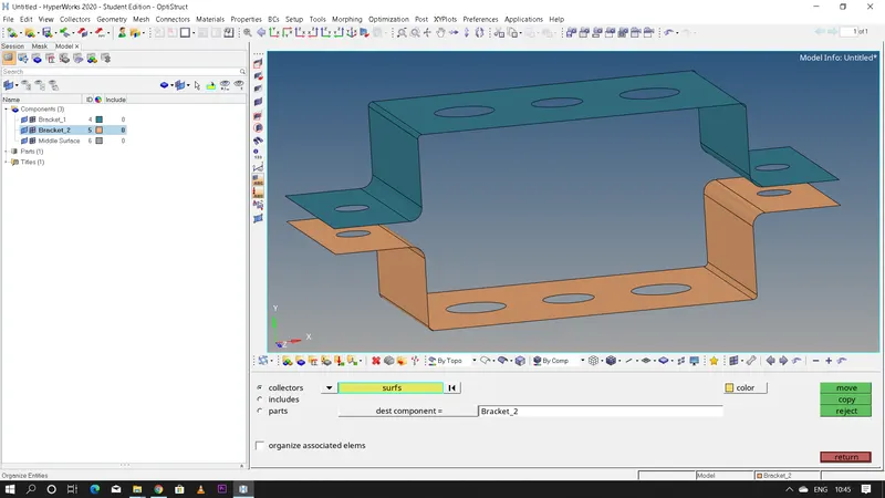
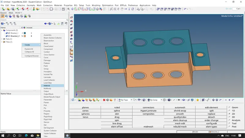
- Now to make the 2D midsurface into a 3D component first we need to create a material and give the thickness for that material.
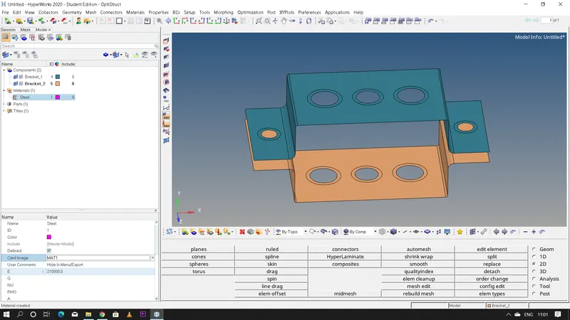
- Steps to be followed: Right click and create a material >> rename it as steel >> select the card image based on the solver >> keyin all the parameters like Young's modulus(E),Rigidity Modulus(G),Poisson's ratio,Density and so on.
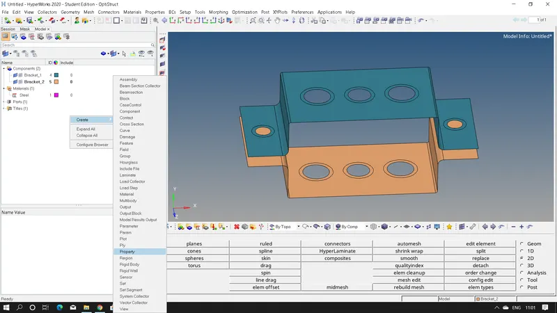
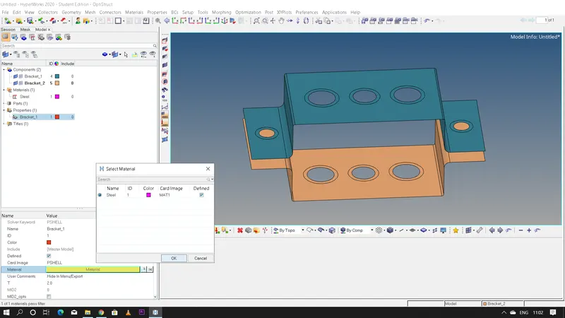
- Right click and create a new property for 'Bracket-1' and 'Bracket-2' seperately >> select card image as PSHELL for both the brackets >> select material as steel >> give thickness values as '2mm' and '2.5mm' for 'Bracket-1' and 'Bracket-2' respectively.
- Now after creating both material as well as the property click on the component and assign it to the respective component.We have to just assign the property and it will automatically assign the material.
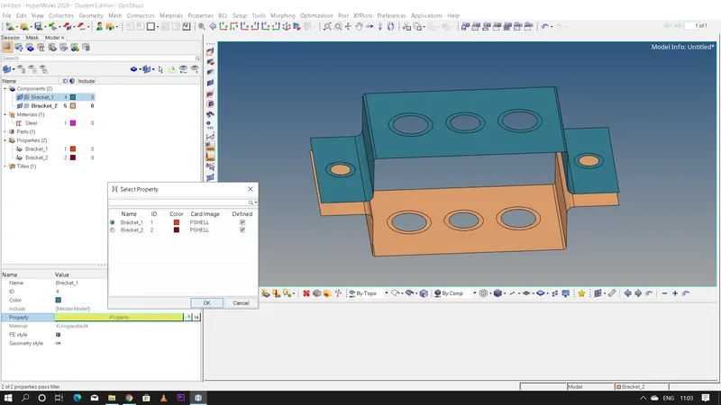
- After giving all the values to both the brackets now let us perform the '2D meshing' for both the brackets but before doing that let us give washer split for all the holes present in the bracket.
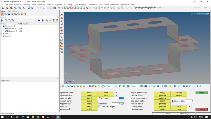
- Steps for giving washer split: Geometry >> quick edit >> washer split >>offset value of 5mm >> select the holes to deploy the washer split.
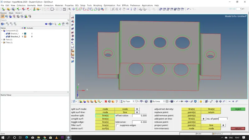
- Steps for creating a 2D mesh: 2D >> automesh >> element size=8mm >>mesh type=mixed >> select the surfaces displayed >> click mesh.
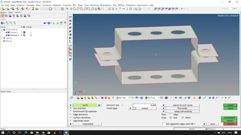
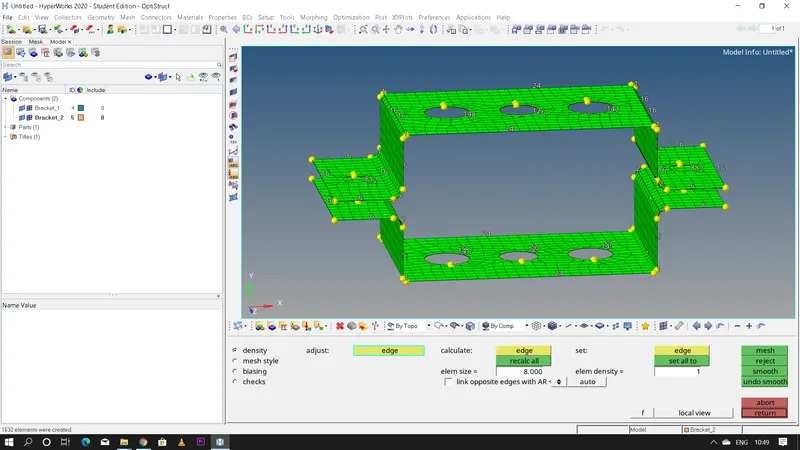
- Make sure that the washer split is captured properly if not change the node values so that the mesh is captured properly i.e, by increasing or decreasing the node values.
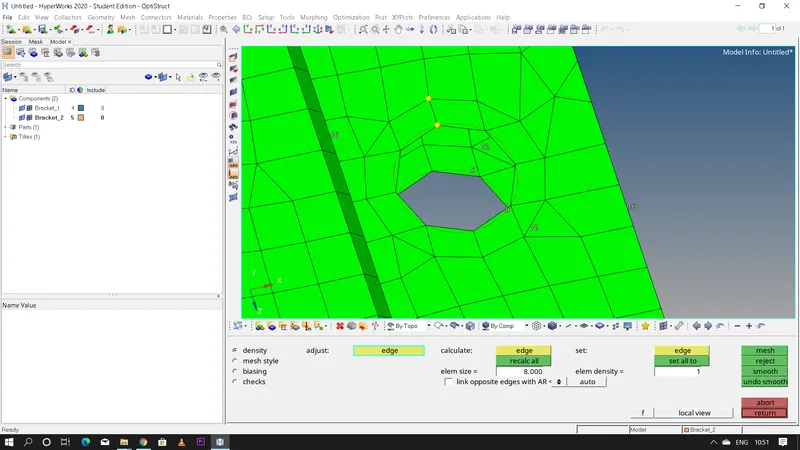
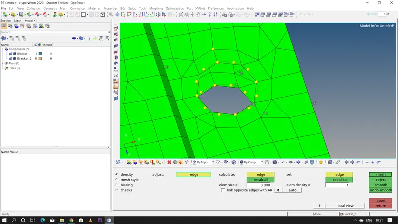
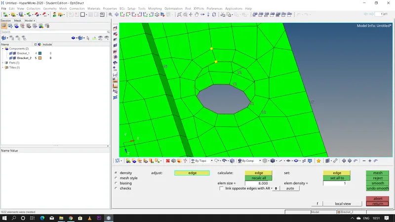
- Hence now after completing the 2D meshing we have to create the 1D element as we have enough number of nodes,so now let us create a rigid element.Rigid elements are basically "RBE2" and "RBE3" elements.
- "RBE 2" elements have infinite abount of stiffness which means it doesn't possess any kind of movement in any direction unless and untill we give any "DOF" for the element and the load distribution is also uniform between all the nodes that are connected irrespective of the distance and position.
- "RBE 3" elements has a unique feature here the load distribution between the nodes that are connected depends on the distance between the nodes i.e, the nodes which are closer will have more load acting on them than that of the nodes which are farther from the base node comparatively.
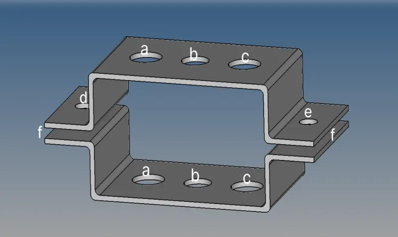
- Here we need to create 1D elements on the following component with given cross-section and DOF.
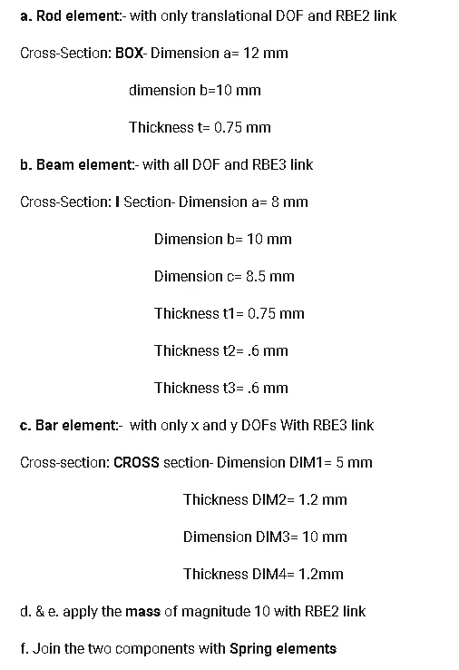
a. Rod element: with only translational DOF and RBE2 link
- Steps to create RBE2 link: 1D >> rigids >> element type=RBE2 >> uncheck DOF1,DOF2 and DOF3 >> select the nodes >> create
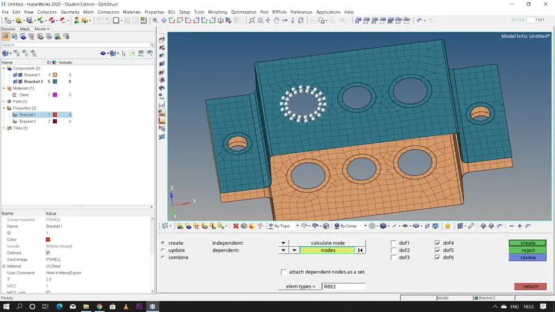
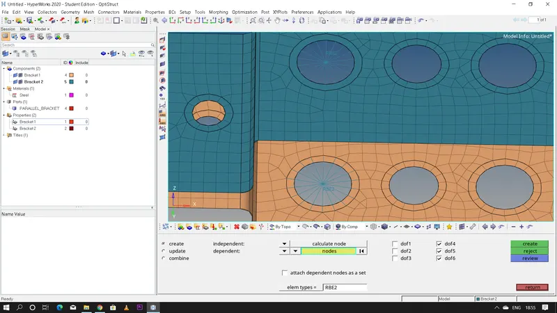
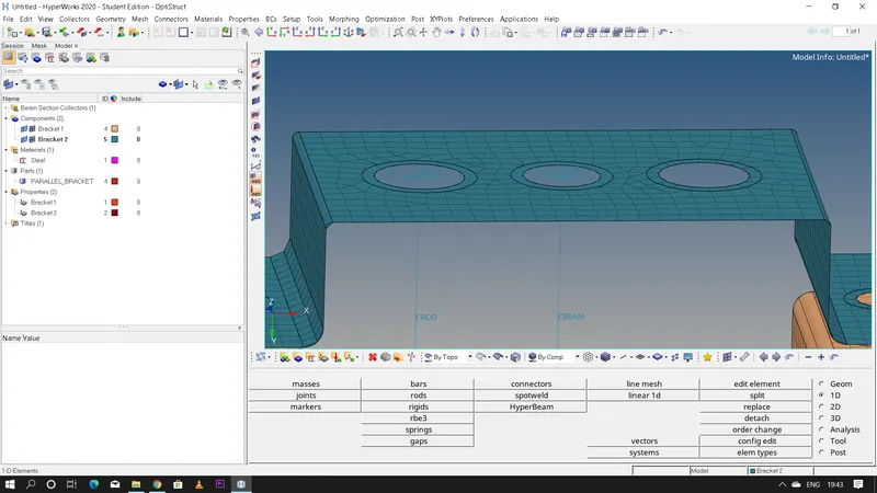
- Steps to create rod element: 1D >> rods >> element type=CROD >> select the nodes
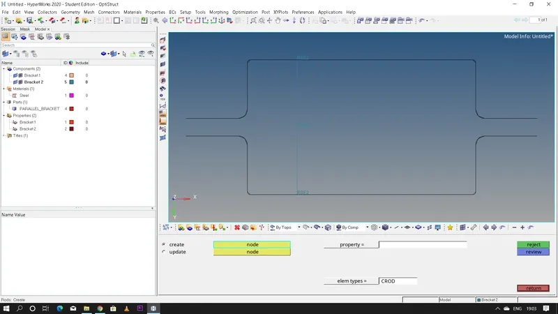
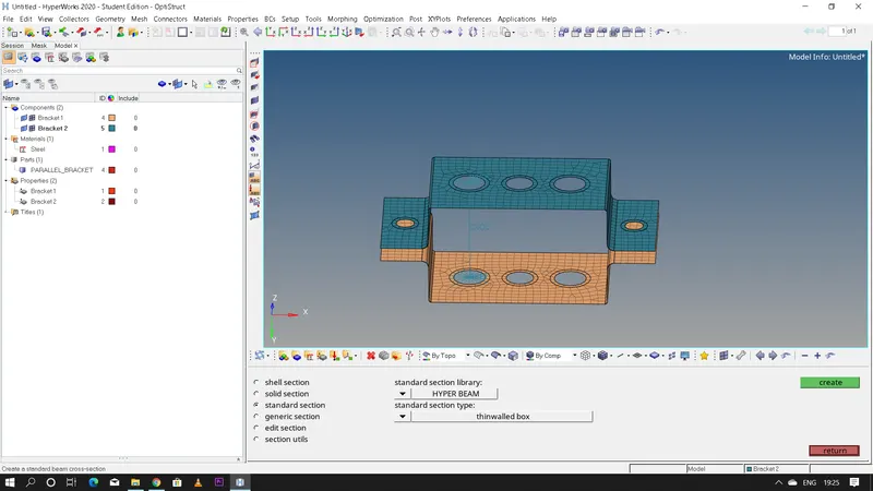
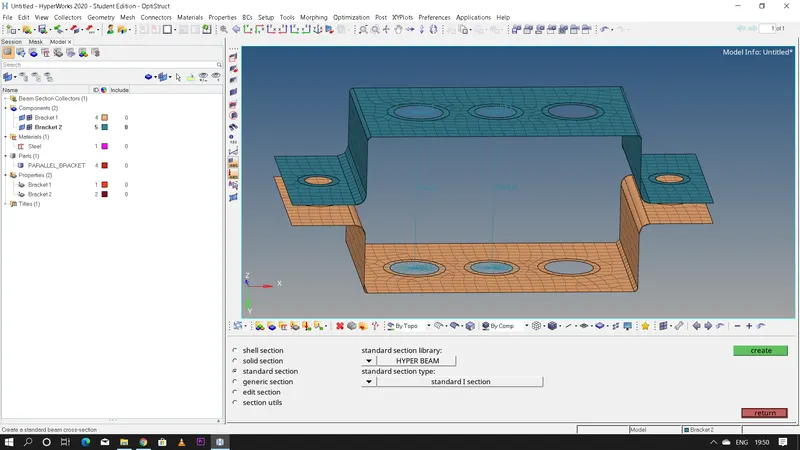
- "Hyper beam" is a part of hypermesh where we basically create cross section for the 1D elements like Rod,Beam and Bars.In hyperbeam we have few sections like: (a) Shell section (b) solid section (c) standard section (d) generic section (e) edit section (f) section utils
- But we usually dont use the "Shell section" and the " Solid section" we only need standard and generic section in most of the cases.
- In generic section we can create our own section.
- In standard section we have further 2 sections like "Hyperbeam" and "Optistruct" which has a lot of different cross sections in it which we can select,create and edit.
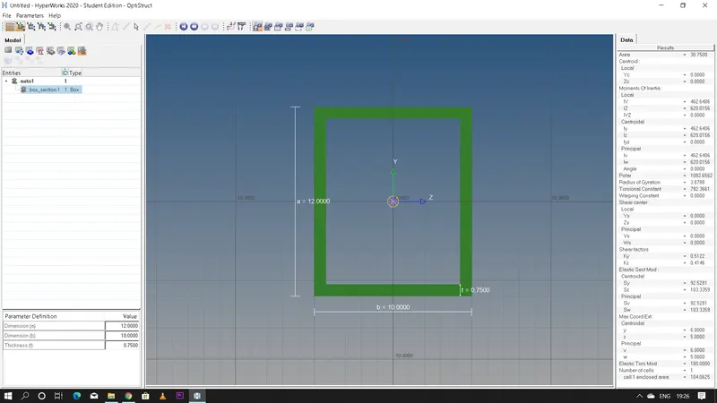
- Now here we need to create a box cross section with the given dimensions.
- Steps to create a Box c/s in Hyperbeam: 1D >> hyperbeam >> standard section >> hyperbeam >> thinwalled box >> create >> edit a=12,b=10 and t=0.75
b. Beam element: with all DOF and RBE3 link
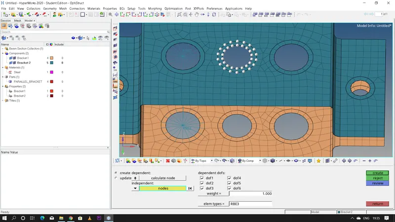
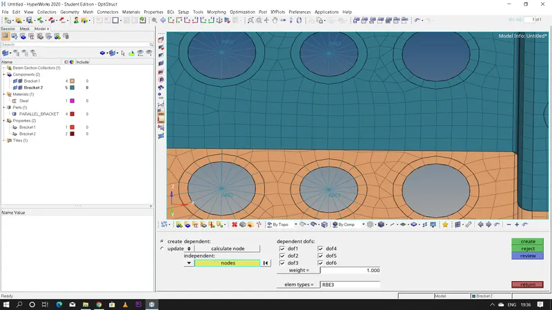
- Steps to create RBE3 link: 1D >> rbe3 >> constrain all DOF >> select the nodes >> create
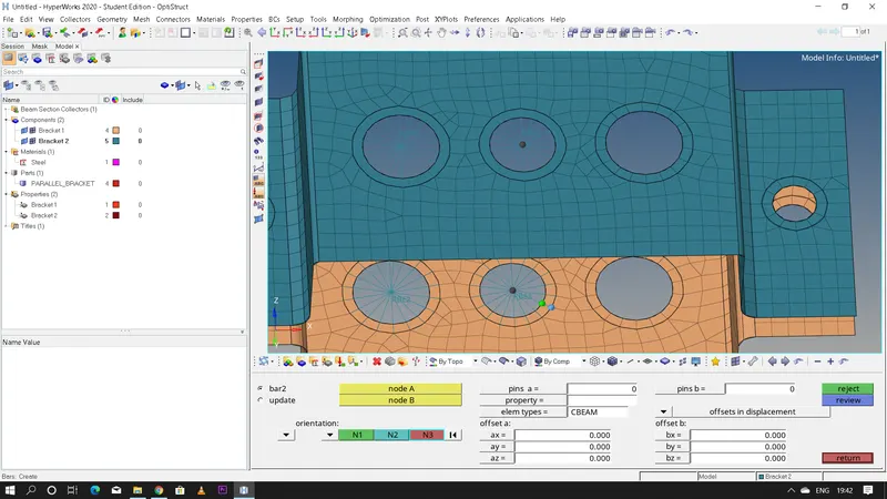
- Steps to create beam element: 1D >> bars >> element type=CBEAM >> select 'node A' and 'node B' >> select vectors 'N1','N2', and 'N3'
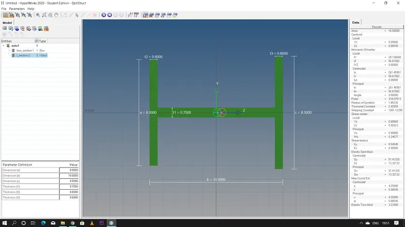
- Steps to create I section: 1D >> hyperbeam >> standard section >> hyperbeam >> standard I section >> create >> edit the dimensions as required

c. Bar element: with only X and Y DOF's and with RBE3 link
- steps to create RBE3 link: 1D >> rbe3 >> uncheck 'dof1' and 'dof2' >> select the nodes >> create
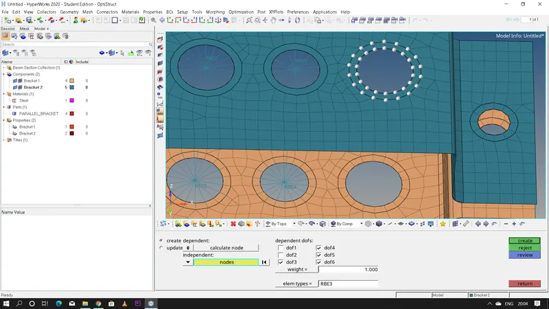
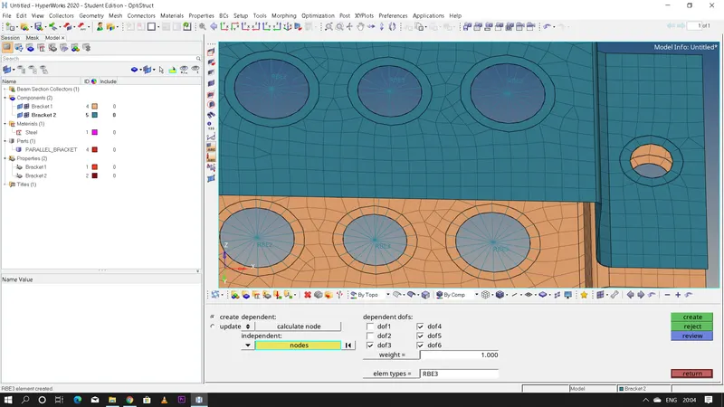
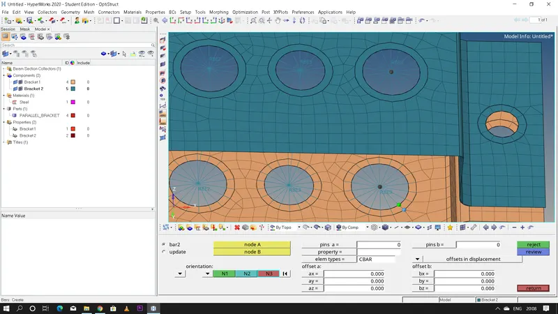
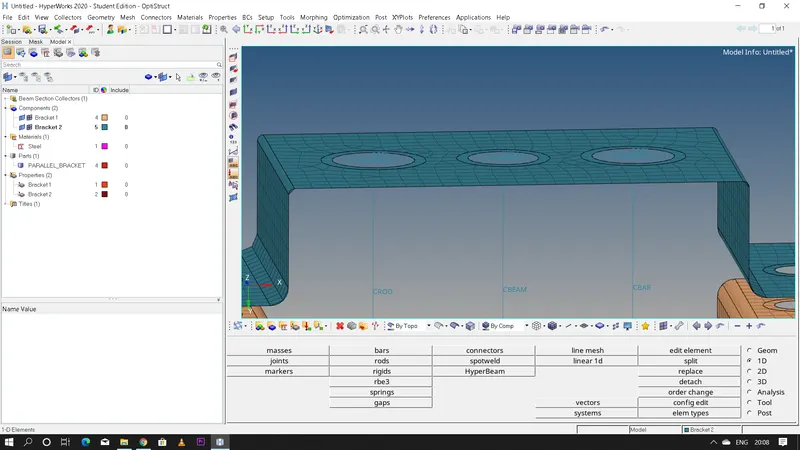
- Steps to create bar element: 1D >> bars >> element type=CBAR >> select 'node A' and 'node B' >> select the vectors N1,N2 and N3
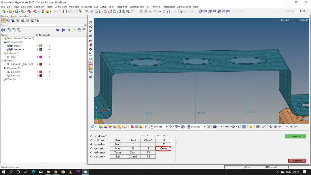
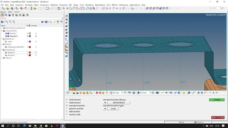
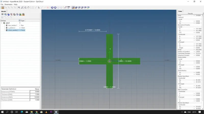
- Steps to create "CROSS" section: 1D >> hyperbeam >> standard section >> optistruct >> cross >> create >> edit the dimension values as per requirement
- Now create properties for Rod,Bar and Beam sections has they have their own properties.
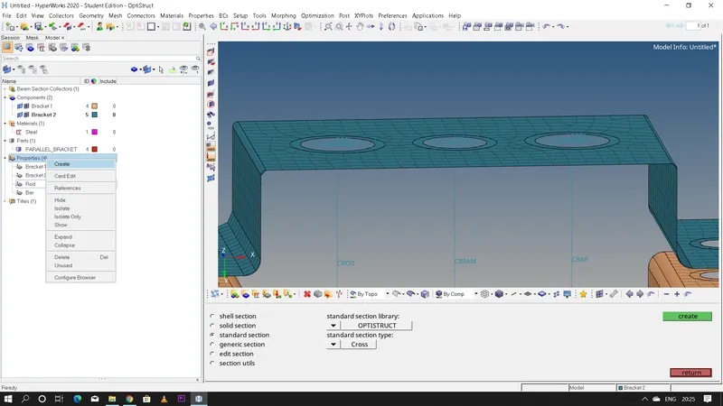
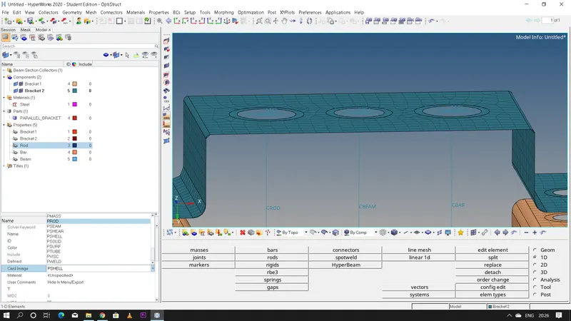
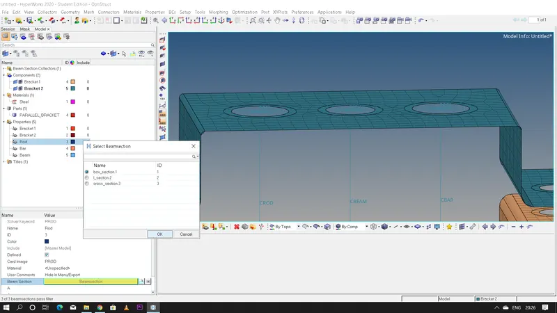
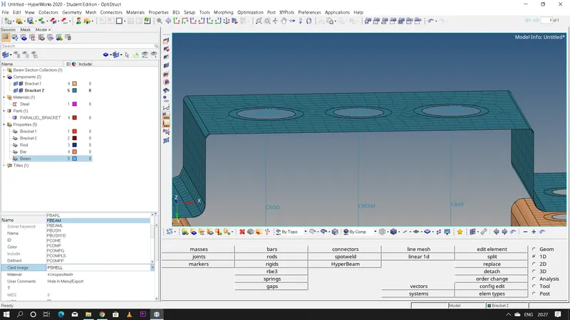
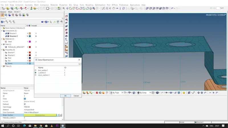
- Steps to be followed: Right click and create 3 new properties >> rename it as 'Rod','Beam' and 'Bar' respectively >> change the card image to 'PROD','PBEAM' and 'PBAR' respectively >> change the section to 'box','I' and 'Cross' sections respectively
* ROD:
* BEAM:
* BAR:
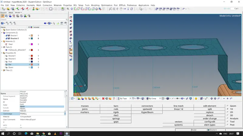
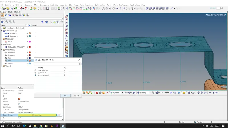
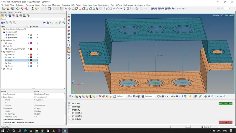
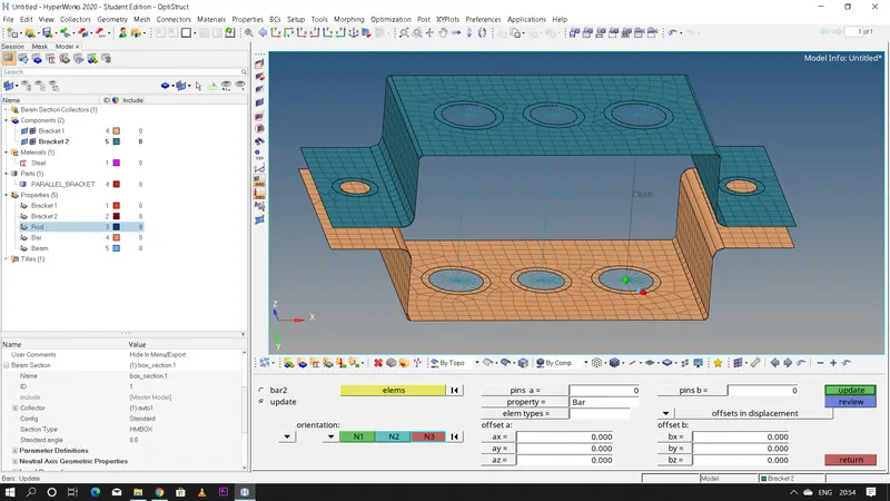
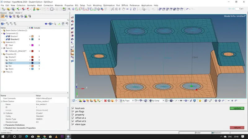
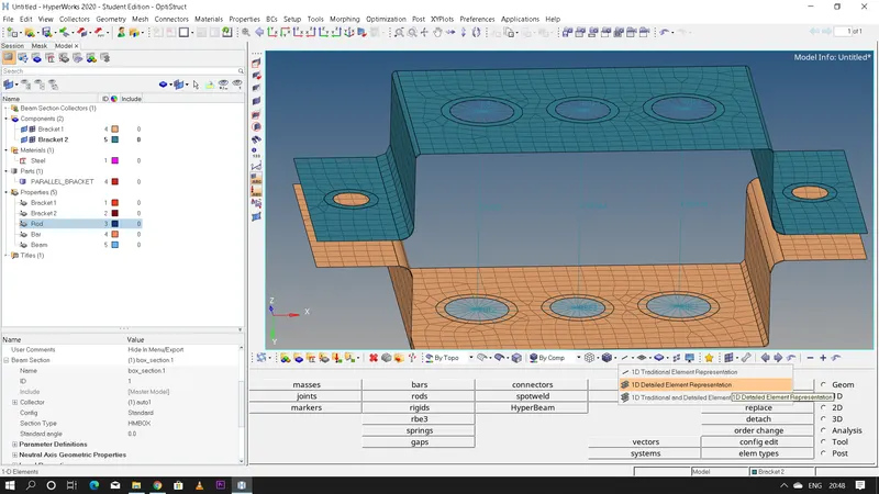
- After creating all the properties now we need to update these properties for the Rod,Beam and Bar so that we can convert the 1D element into 3D section by enabling the "1D detailed element representation".
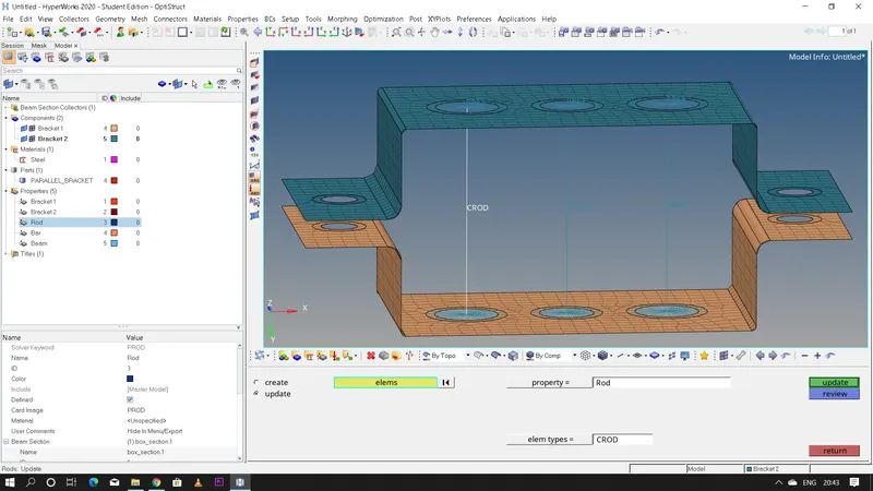
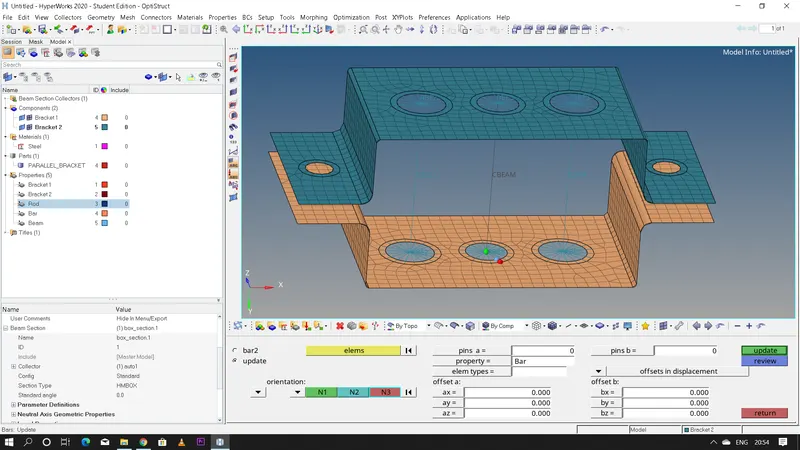
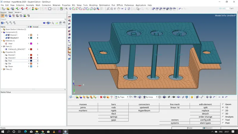
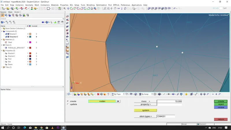
- Create an RBE2 link and add a mass of 10 magnitude at 'd' and 'e' holes as given
- steps to add mass: 1D >> masses >> magnitude=10 >> element type=CMASS1 >> select the nodes >> create
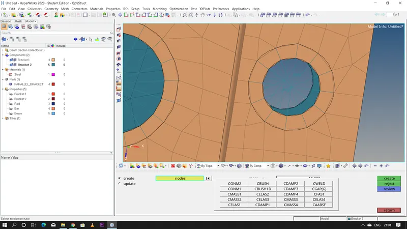
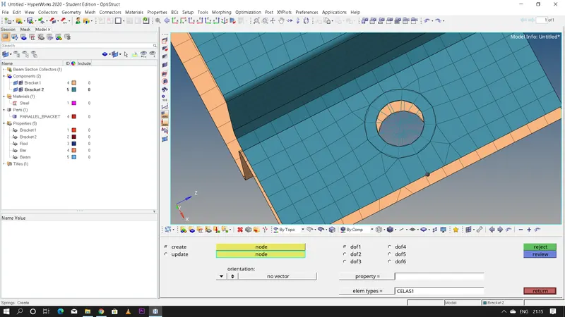
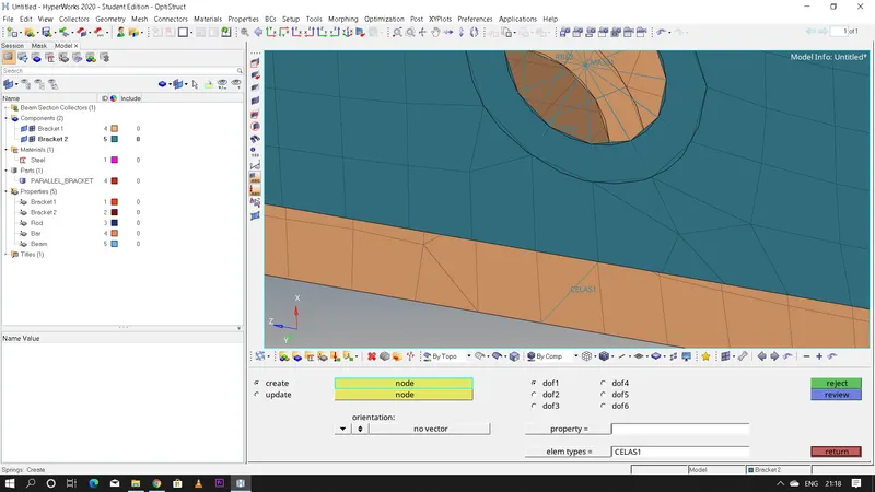
- Finally join both the brackets with spring elements
- steps to create spring elements: 1D >> springs >> element type=CELAS1 >> select the nodes >> spring element will be deployed
- Final Bracket:
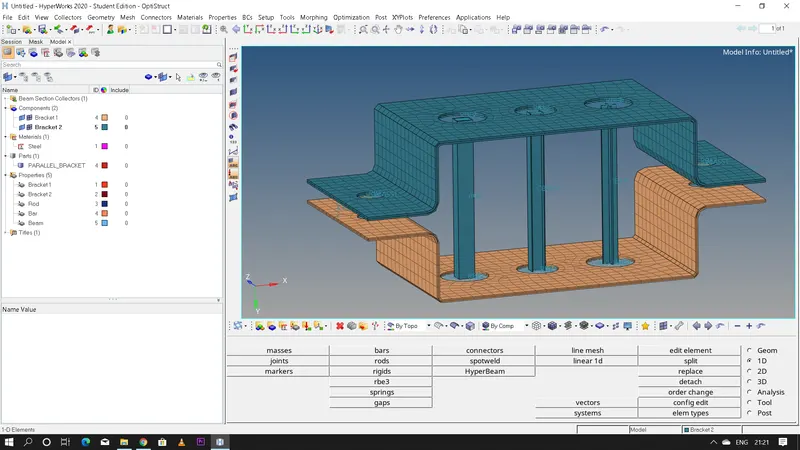
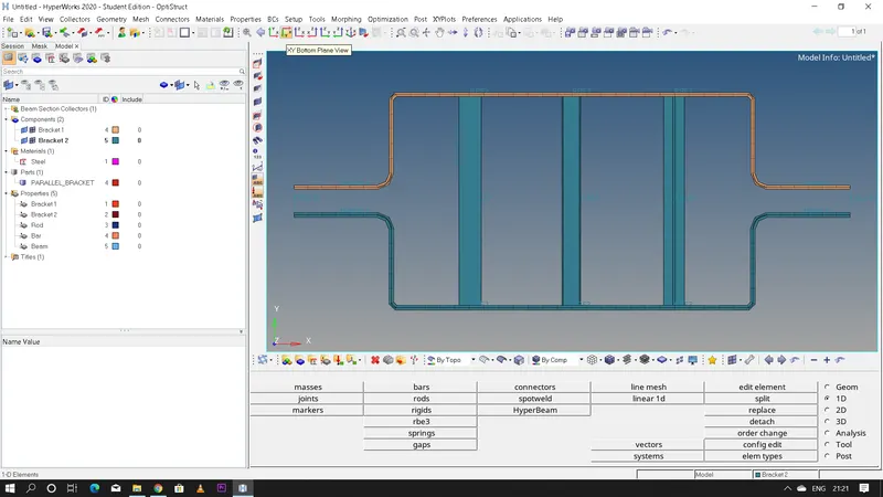
- Conclusion: Hence the given bracket is meshed,1D elements are created as per the given data and cross section is also created using hyperbeam with the exact dimensions given and assigned the property.