Week 4- Challenge
Aim:
The aim is to create a 1D model with the following components with the given cross-section and Degrees of Freedom(DOF).
Rod element:
With only translational DOF and RBE2 link Cross-Section: BOX
Dimension a= 12 mm
Dimension b=10 mm
Thickness t= 0.75 mm
Beam element:
with all DOF and RBE3 link
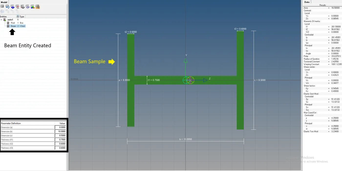
Cross-Section: I Section
Dimension a= 8 mm
Dimension b= 10 mm
Dimension c= 8.5 mm
Thickness t1= 0.75 mm
Thickness t2= .6 mm
Thickness t3= .6 mm
Bar element:
With only x and y DOFs With RBE3 link
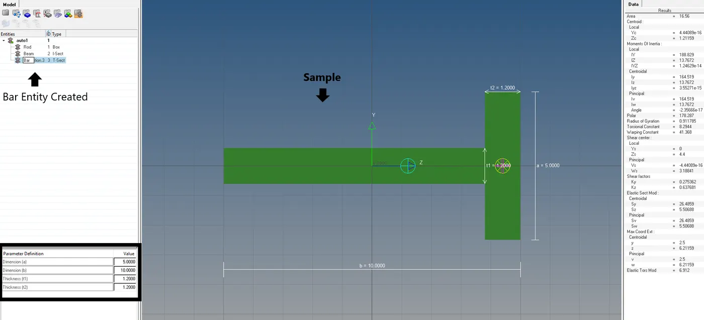
Cross-section: CROSS section
Dimension DIM1= 5 mm
Thickness DIM2= 1.2 mm
Dimension DIM3= 10 mm
Thickness DIM4= 1.2mm
d & e. apply the mass of magnitude 10 with RBE2 link
Join the two components with Spring elements
Methodology:
The methodology to perform the 1D elements with the given components is as follows.
- Opening the file.
- Creating the Mid-Surface.
- Creating a new Component and Property.
- Creating the mesh.
- Generating the RBE2 and RBE3 elements.
- Creating Rod, Bar, and Beam Structures.
- Add Spring Element.
- Giving Mass to Spring Component
Theory:
Mid-Surfacing:
Mid Surfacing is the process to create a middle surface of the given model. The mid surface is generally, taken to create the mesh with disturbing the parent geometry. Thereby, by checking if the model is suitable for the process or the design changes should be done on the model to improve the quality of it.
The mid surface modeling process relies on an accurate solid model as the starting point. Midsurface modeling is best suited to thin solids or thin-walled solids where wall thickness is constant or where reasonable approximations of the wall thickness at each point can be made easily. You can apply mid surface modeling to any solid cell within a model; you need not apply it to the entire model. If you apply mid surface modeling to only a portion of a solid model, Abaqus/CAE automatically creates shell-to-solid coupling constraints to couple the motion of the mid surface shell edges to that of the remaining solid model faces. Shell-to-solid coupling constraints will not be created if the angle between the shell surface and the solid face deviates significantly from 90°.
Procedure:
- Opening the File:
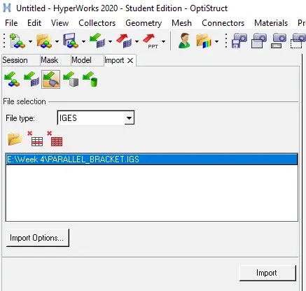
- Initially, the File is opened using the import geometry tool.
- In Import Geometry, Select IGES type and open the file.
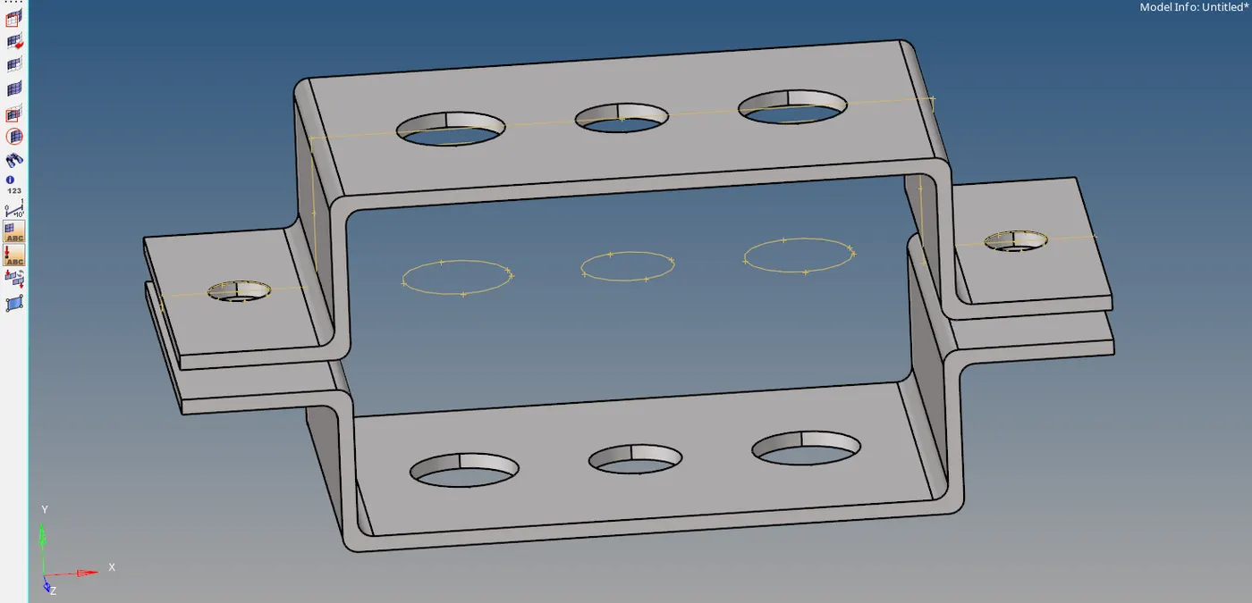
- The model is then imported.
- Creating the Mid-surface:
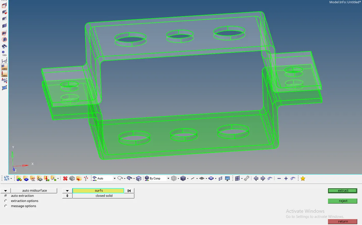
- The Mid Surface is created by using the mid surface option in the Geometry tab
- Midsurface >> click on auto Extraction >> Select the surfaces>> Click Extract.
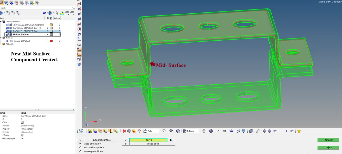
- The Mid Surface is created. To assign Mid surfaces for each part, the next segment explains it clearly.
- Creating the new component and property:
- The Mid surface when created creates a new component as mid surface.
- You can either rename the component or to move the component to another component using the organizing tool.
- Select Tools >> Click organize >> Select collectors >> select surfs option >> Select the Surface to move >> Click Move.
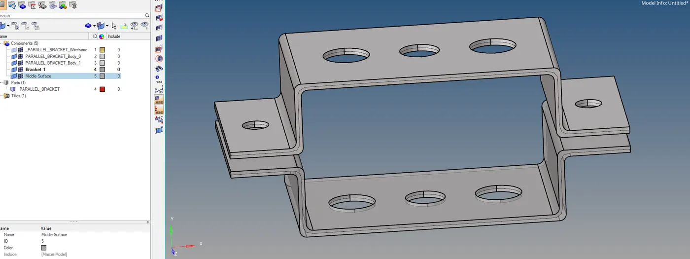
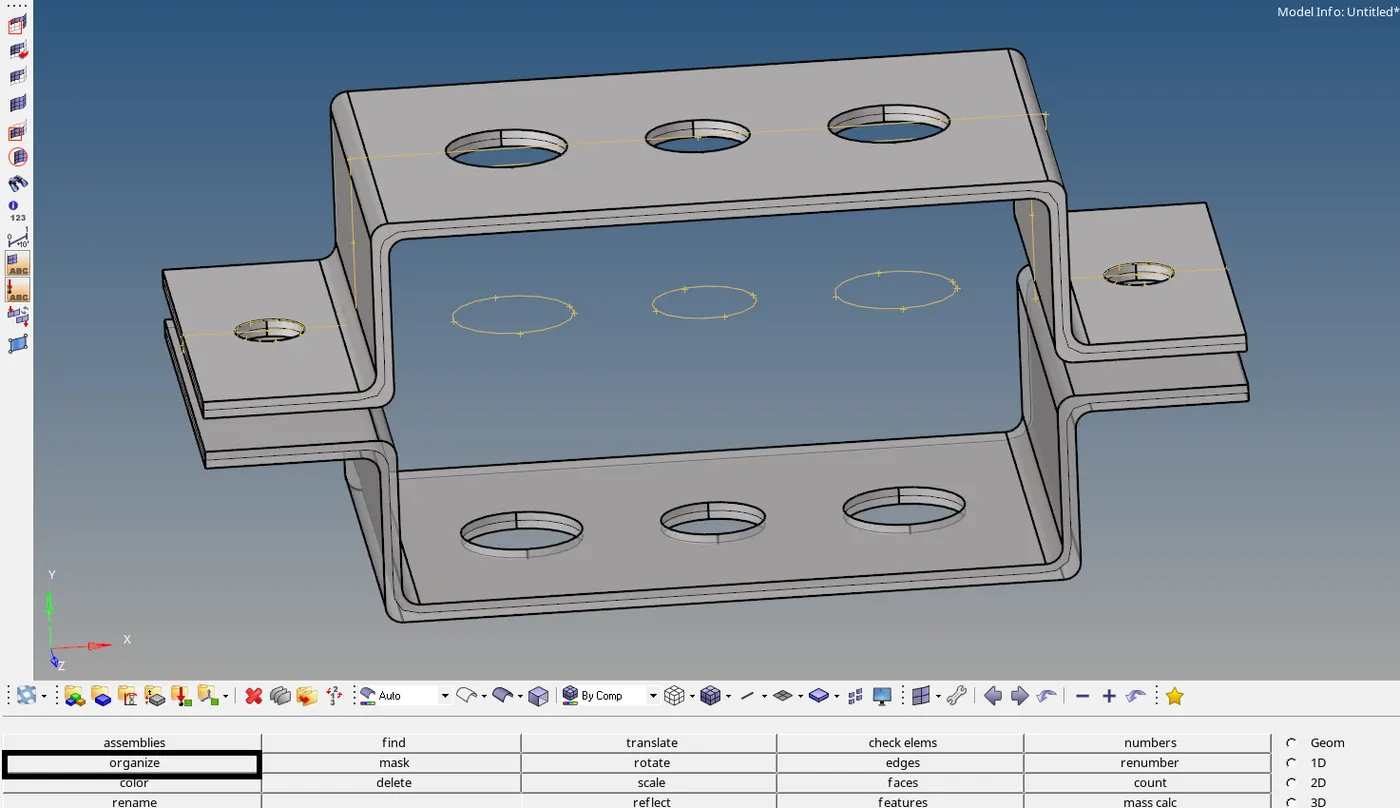
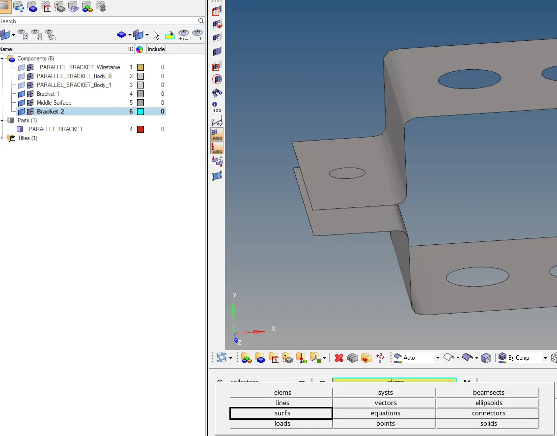
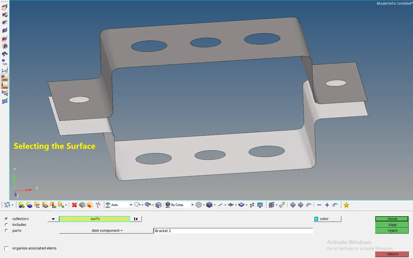
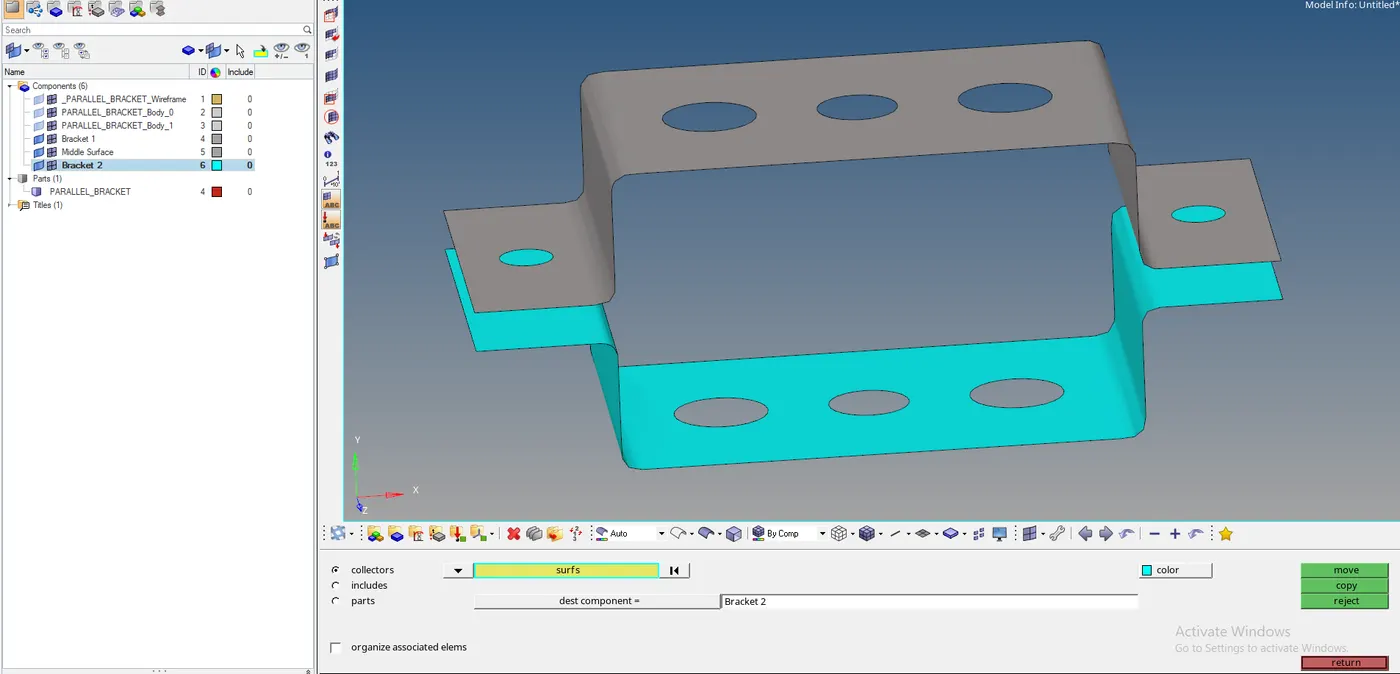
- The Component is moved.
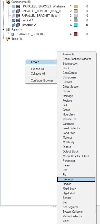
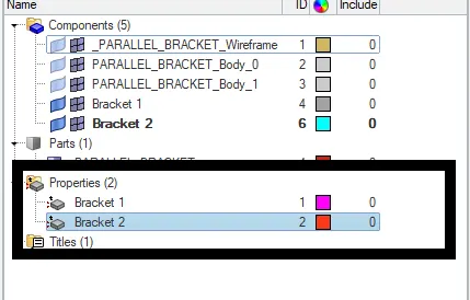
- For the Property Generation, On the Tab bar >> Right-Click >> Select Create >> Property >> Name The Property.
- Now, to assign the property to the component, click on the component >> On the Bottom left, the status bar appears, select property >> give the property you want to assign to it.
- The Property is assigned to the component.
- Creating the mesh:
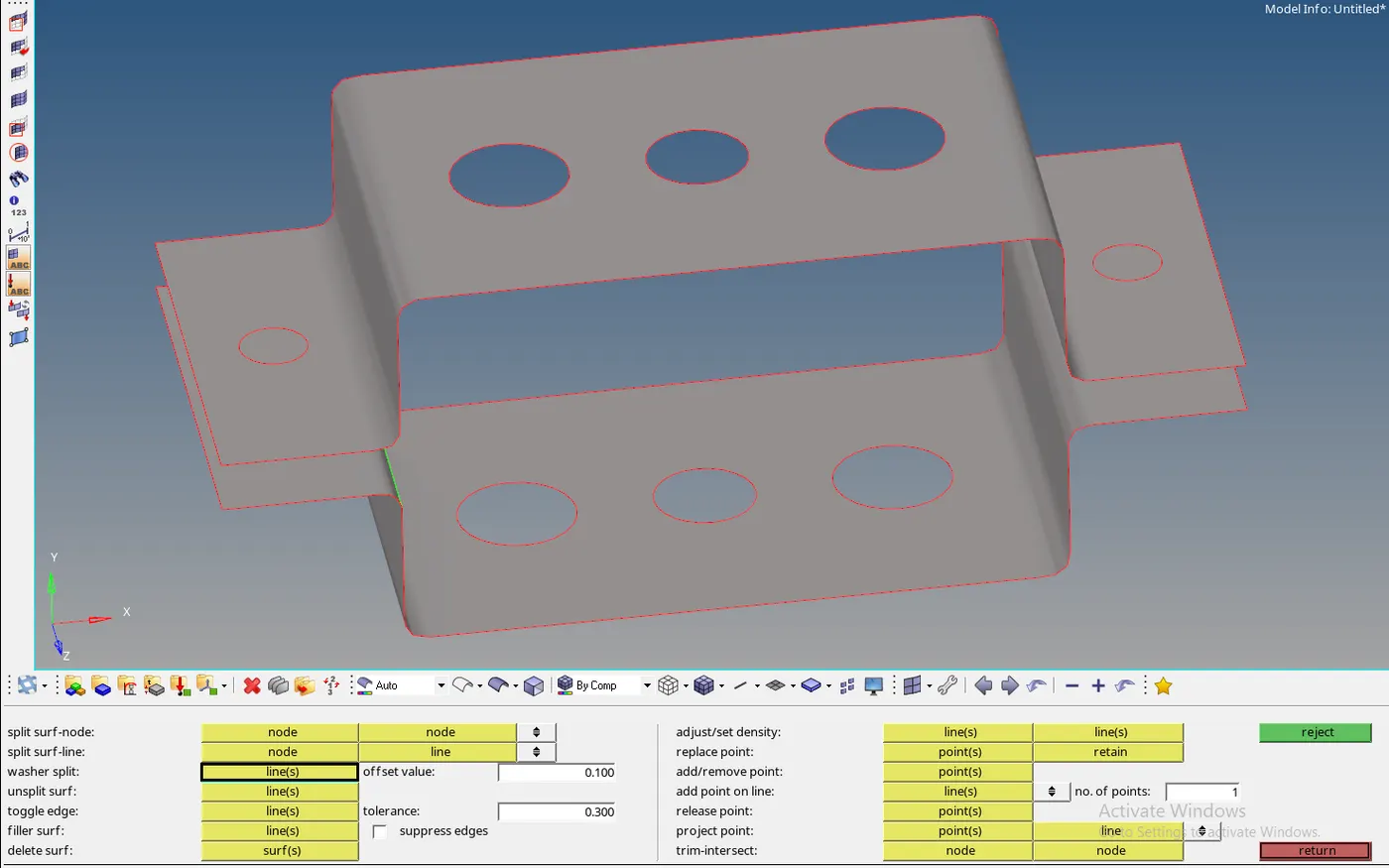
- The Model contains some holes in it and therefore to create the proper mesh over the free edges the washer split is used.
- In Geom Tab >> Select Quick Edit>> Select Washer Split >> Give the Offset Value >> Select the Free Edge Circles.
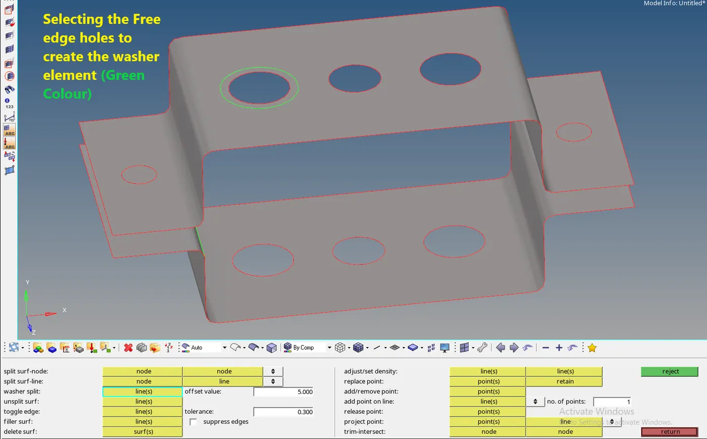
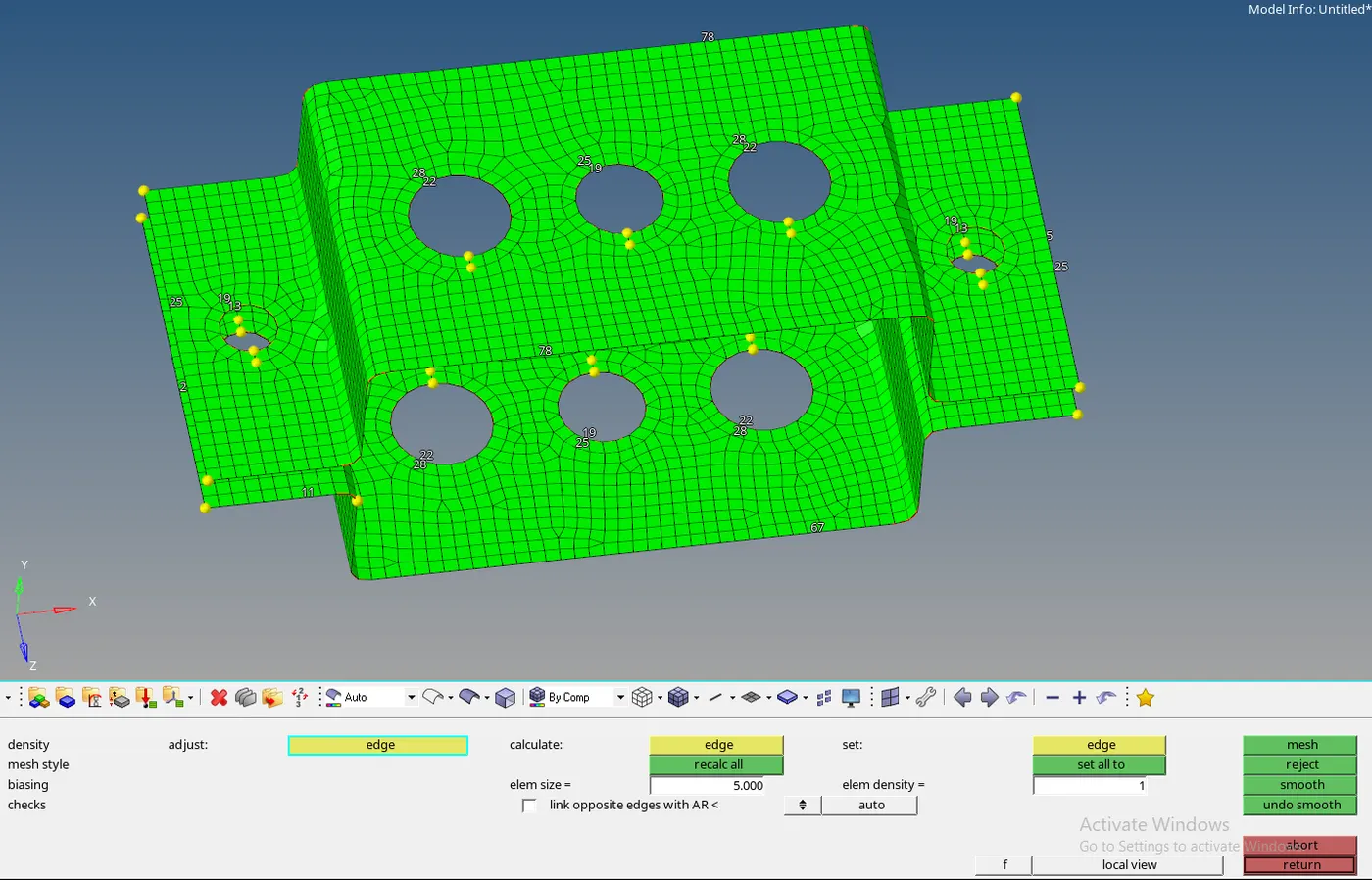
- For meshing, Select automesh in 2D Tab >> Select Surfaces >> Select Element size >> Select Mesh type as mixed >> click Mesh.
- Generating the RBE2 and RBE3 elements:
- For both RBE2 and RBE3 the Process is similar.
- For RBE2, Go to the 1D tab >> Select Rigids >> Select Calculate nodes >> Select the Multiple nodes option (from nodes down arrow button) >> Select the nodes (by part- on clicking the nodes option again) >> Select the Degrees of Freedom as per instructions >> middle-click on the mouse.

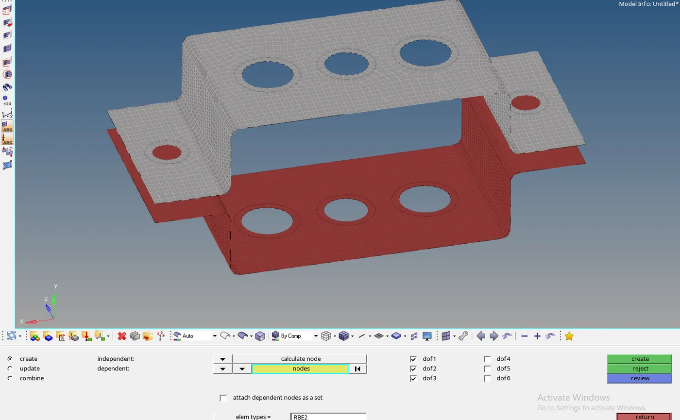
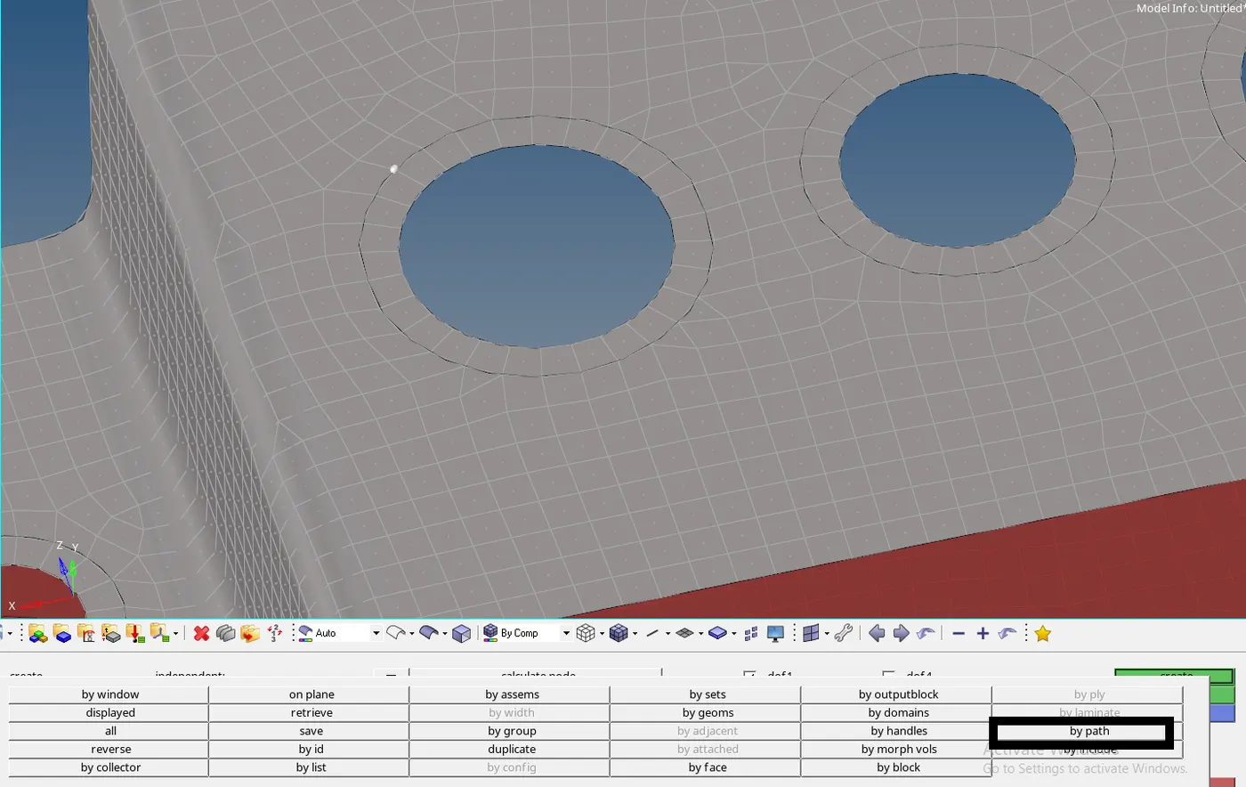
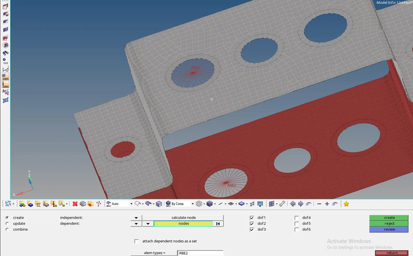
- The RBE2 is created. RBE3 is Similar to RBE2.
- For RBE3, Go to the 1D Tab >> Select RBE3 >> Select the nodes >> Select the Degrees of Freedom as per instructions >> Middle-Click on the mouse.
- The RBE2 and RBE3 are created.
- Creating the Rod, Bar, and Beam Structures:
- The Rod, Bar, Beam are the parts of 1D Elements.
- For Rod:
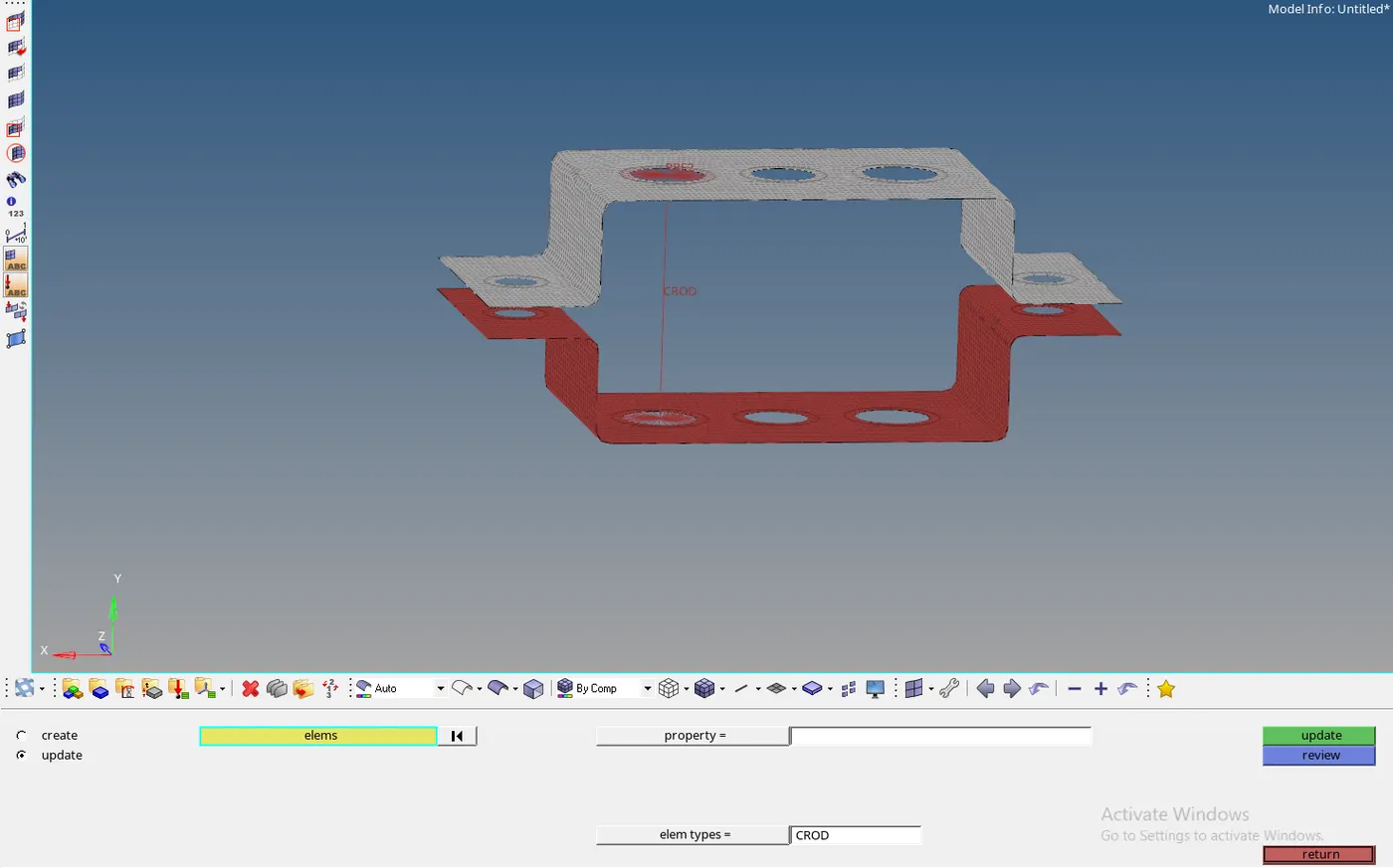
- Select rods >> Select the Nodes for which you want to create the rods >> Select Element types as ‘CROD’.
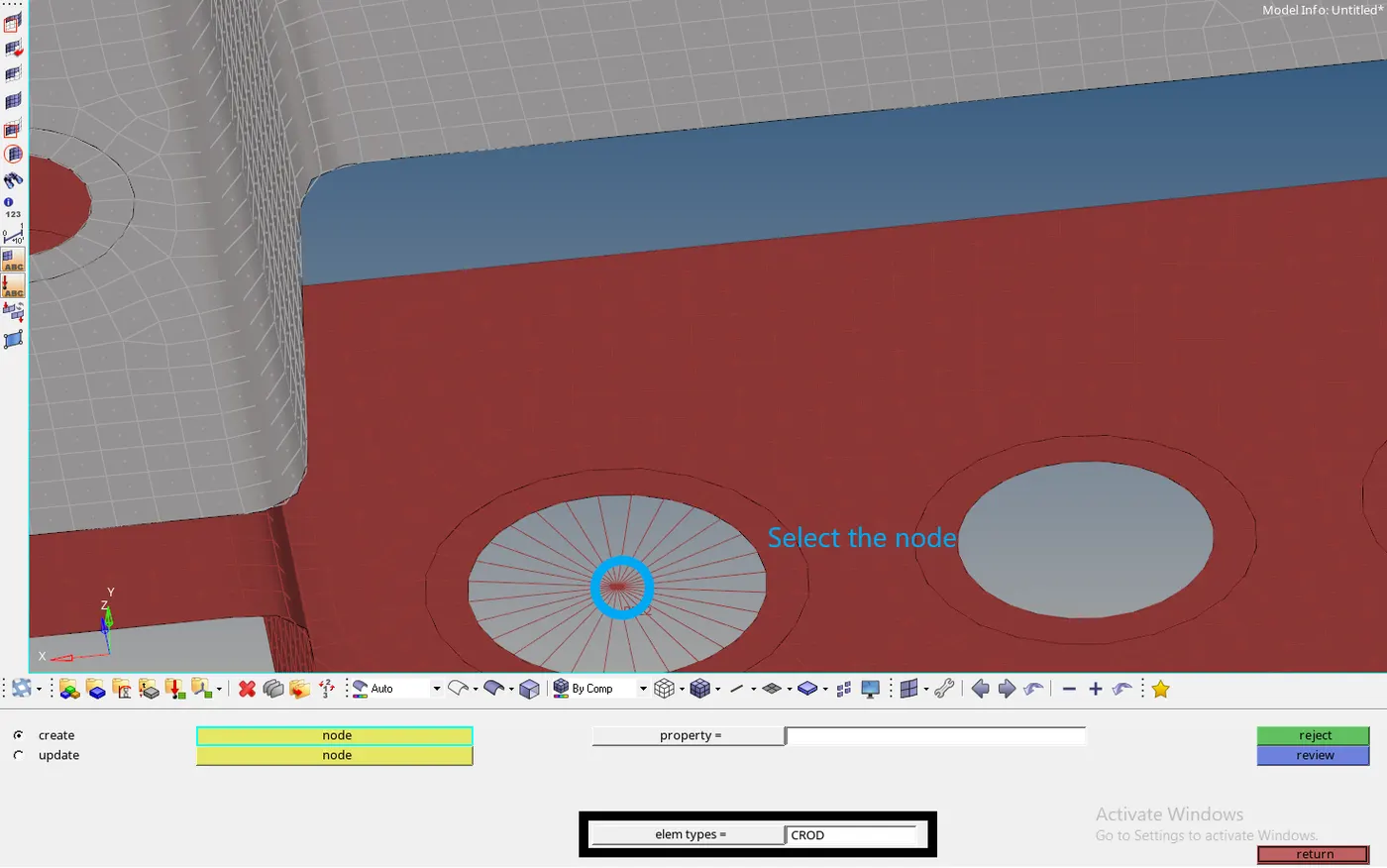
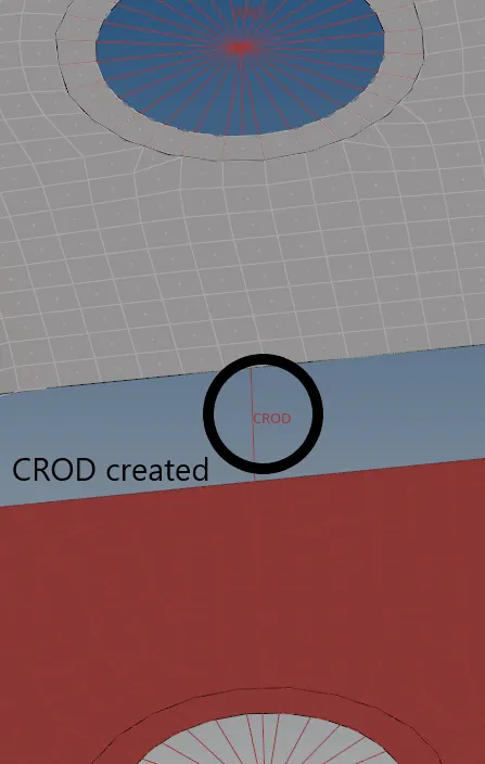
- The Rod is Created. To create a rod structure part, The HyperBeam tool is used.
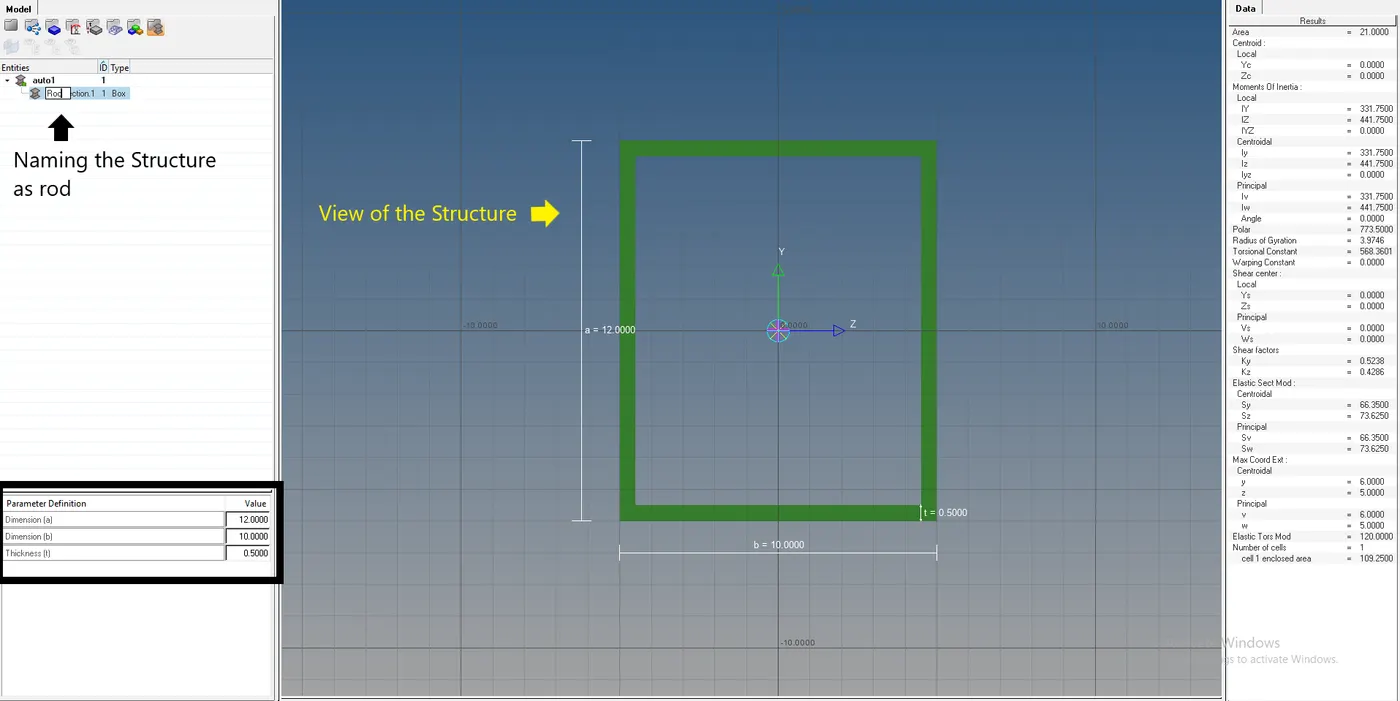
- Select HyperBeam in 1D Tab >> Select Standard section >> Select Standard Section Type >> Select thinwalled box (Given in the Instructions) >> Click Create >> A New Page Opens >> Give the Dimensions as per the instructions. >>Give the name to the Structure as rod >> Go to the Model View.
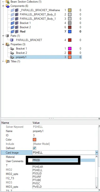
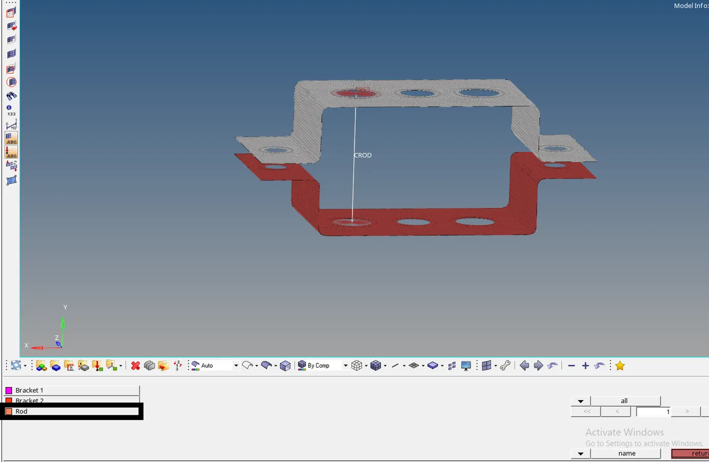
- Now, Create a new Component and property as ‘PROD’ and name it Rod.
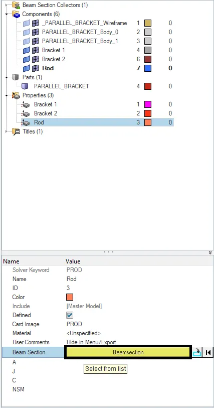
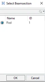
- Select the Property ‘Rod’ >> Select Beam Section >> Select the rod created.
- Click the component (rod) >> Right-Click on it >> click Assign >> Select the Property >> Click OK.
- To update the Property to the component, Go to the rods >> update >> select the element (Rod) >> Select the Property (Rod) >> Click Update.
- The Rod is visually seen.
- The method is similar to Bar and Beam.
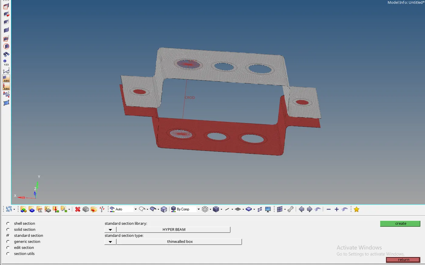
- For Bar:
- Select Bars >> Select the Nodes >> Select the Orientation >> Select the element Type as ‘CBAR’.
- The Remaining process is similar to that of the rod. ( Just while creating the property the type to be selected is ‘PBAR’. and HyperBeam Structure as ‘Standard T section’
- For the Beams:
- Select Bars >> Select the Nodes >> Select the orientation >> Select the Element Type as ‘CBEAM’.
- The process is similar to the rod and the property created is to be in the “PBEAM” type and the HyperBeam Structure as the ‘Standard I section’.
- Adding the Spring Component:
- The Spring Component is Simple.
- Select Springs in 1D Tab >> Select the nodes >> Give the Degrees of Freedom >> Select element type as CELAS1. >> Middle-Click on the mouse.
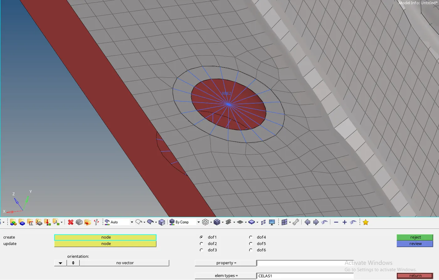
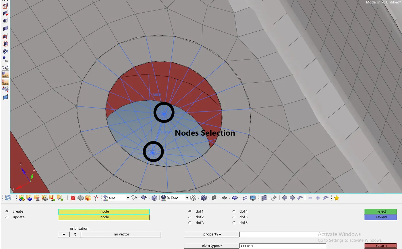
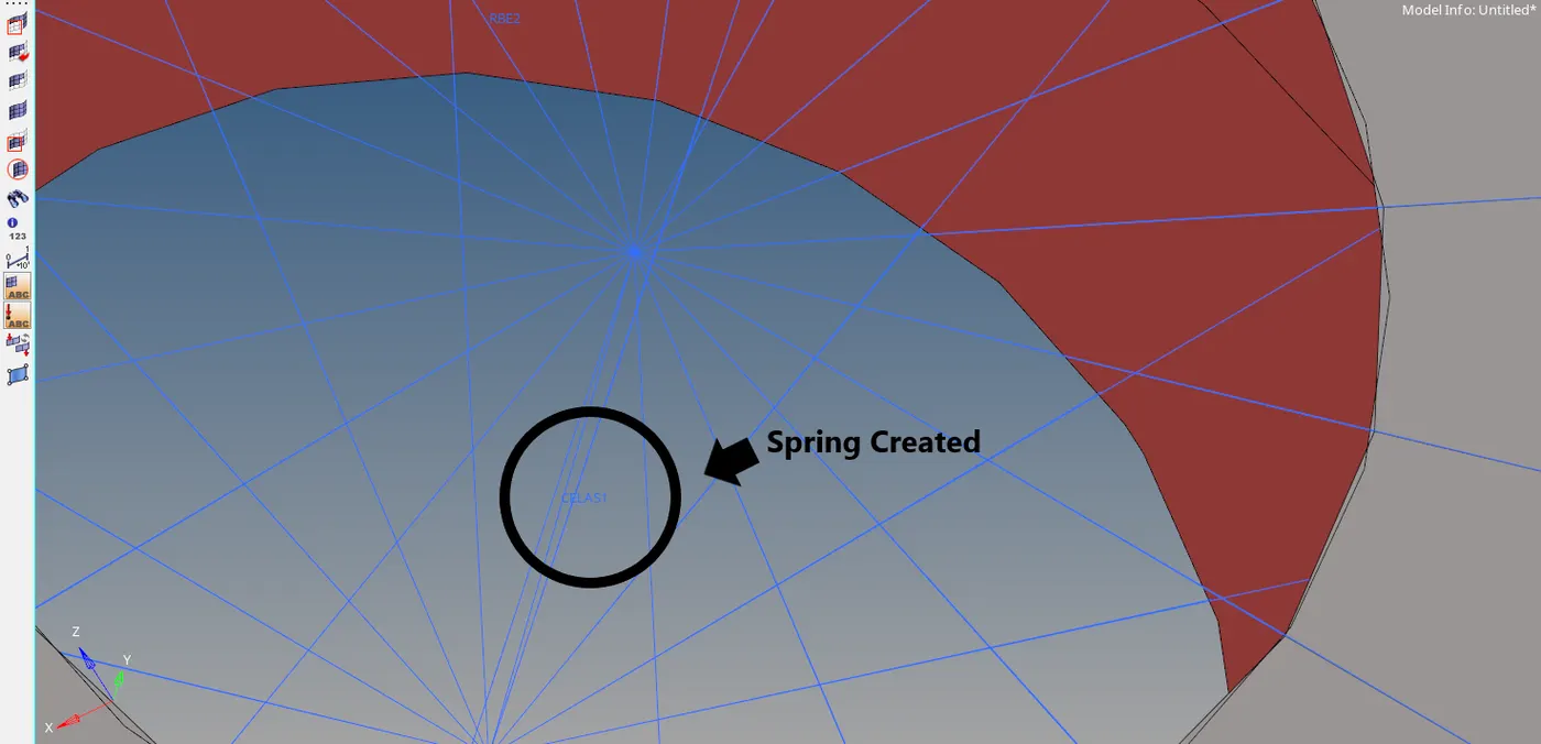
- Giving the mass to the Spring component:
- The mass of the component decides on how much weight does the part should sustain and simulation can check if it is really holding the mass required to it.
- Select masses on 1D Tab >> Select the node >> Give the Mass >> Select the Element Type >> Click Create.
- The mass is created on the particular node.
Result:
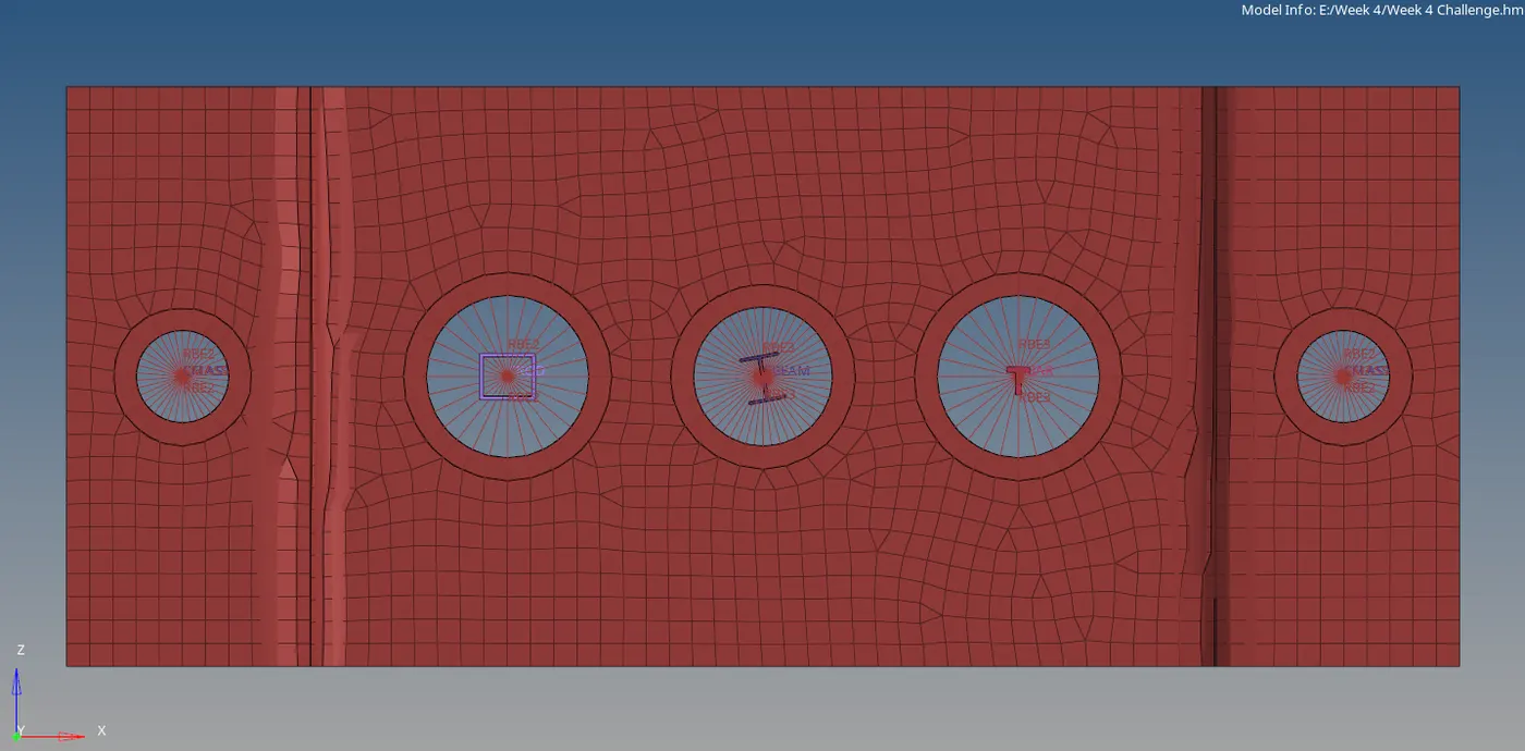
The Mid surfacing and the structures have been created.
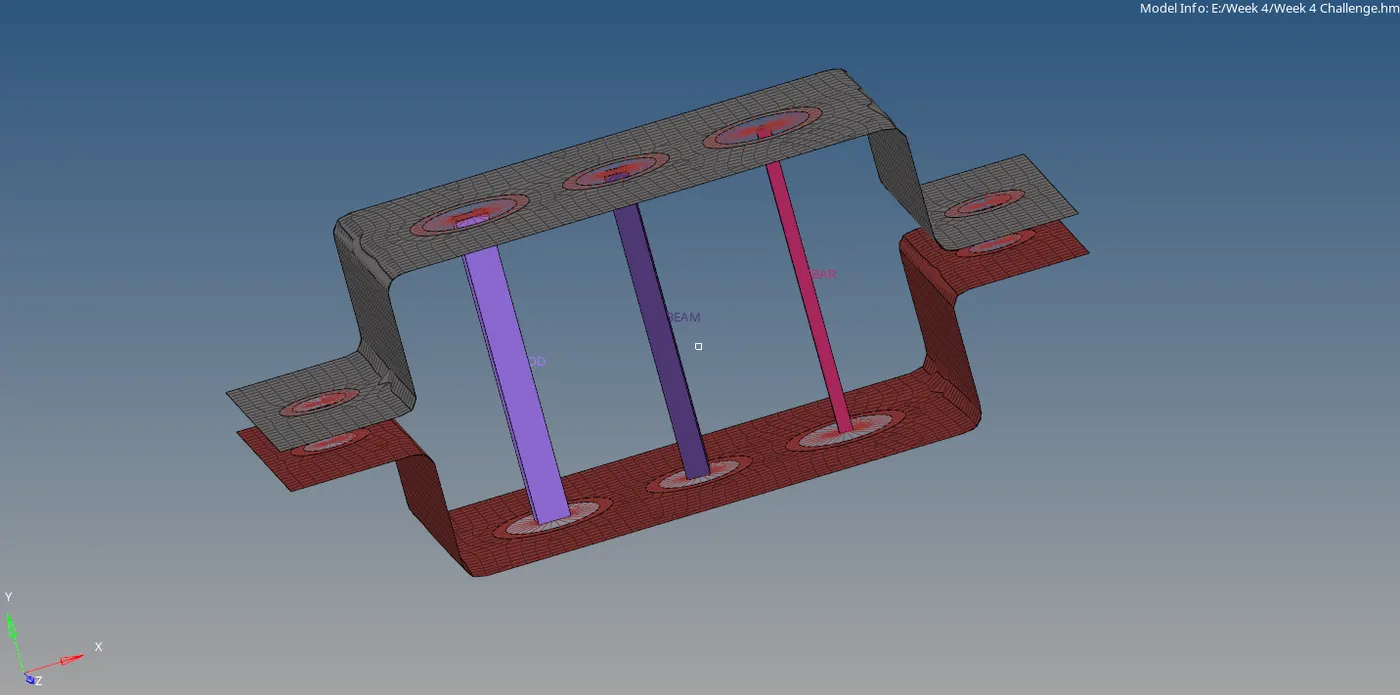
Top View:
Learning Outcomes:
- Learned how to create the mid surface
- Learned how to create RBE2, RBE3.
- Learned how to generate the Rods, Bars, and Beams
Google Link: Week 4 Challenge