Week 4- Challenge
AIM:
To create 1D elements on the given component with given various dimensions and DOF.
METHODLOGY:
- Extracting the midsurface from the given geometry.
- Making the necessary RBE connections.
- Creating the required and mentioned elements with given dimensions and DOF.
INTRODUCTION:
A bracket is used to hold the different closing parts with nut and bolts.
PROCEDURE:
a.Import the model by clicking on "import the geometry" and select the IGES option.
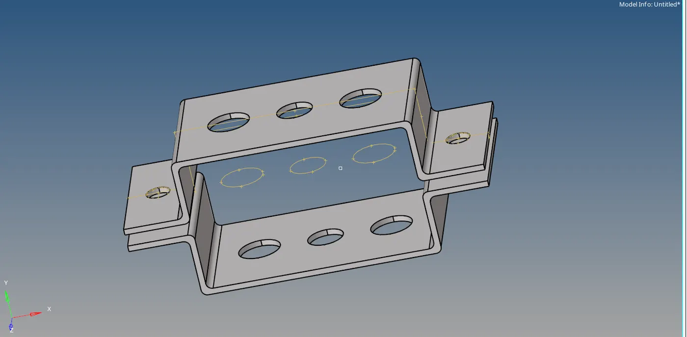
Figure-1( Imported model)
b.Import the geometry.
c.Extract the midsurface from both the surfaces and create a new component part in tool bar.
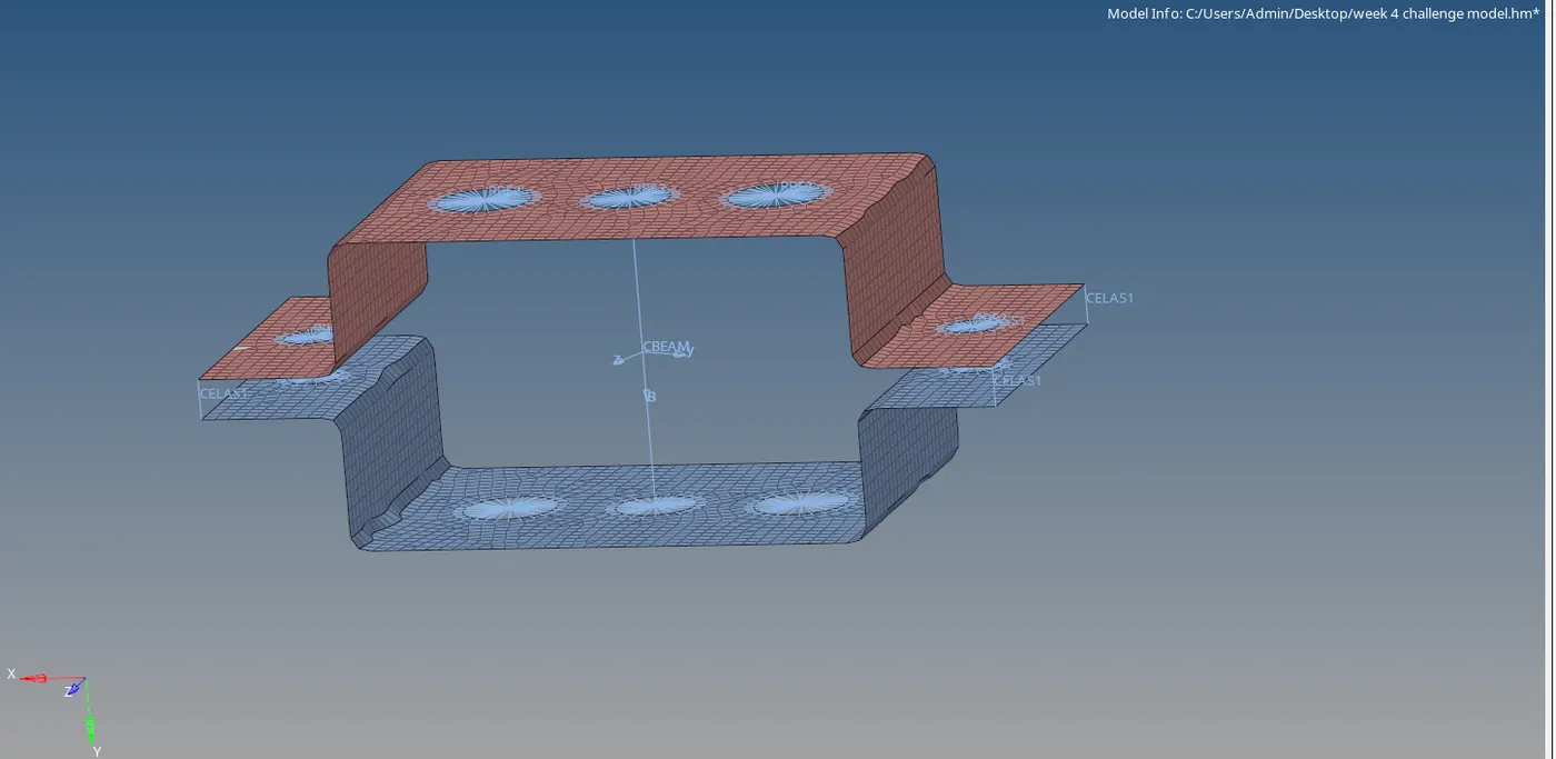
Figure-2( Midsurface)
d. Create the material and property ID's.
e. For both property id's assign the thickness.
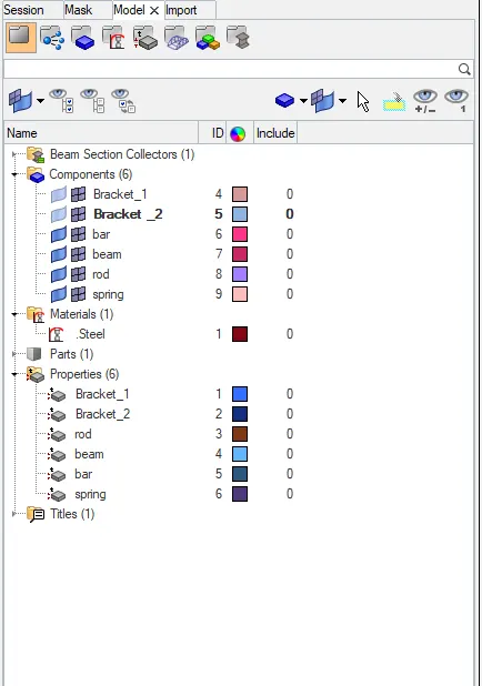
Figure-3(Creating the ID's)
f.Create a material id as "Steel".
g.For midsurface id select the material id and click on Steel property.
Rod:
- Create a rbe2 connection with only translational DOF to a holes on both surfaces.
- Go to 1D options and select rod option.
- Select both rbe2 nodes and select element type as cbar.
- 1d rod element is created between those two nodes.
- To represent rod element as box, select hyperbeam.
- In hyperbeam, select standard section and select thinwalled box as we required box section and create.
- Automatically it opens hyperbeam view,create a box section with given dimensions and return to model view.
- Create a propert ID for rod.
- Select a card image as "PROD" and and select as beam section.
- Go to bars,click on update option and select property type as "rod",click on OK.
- Create a component ID and right click on it.
- Select "assign" and click on apply and then OK.
- Go to tools menu and click on "Organise".
- Select the rod element and dest component as "rod".
- Click on "move".
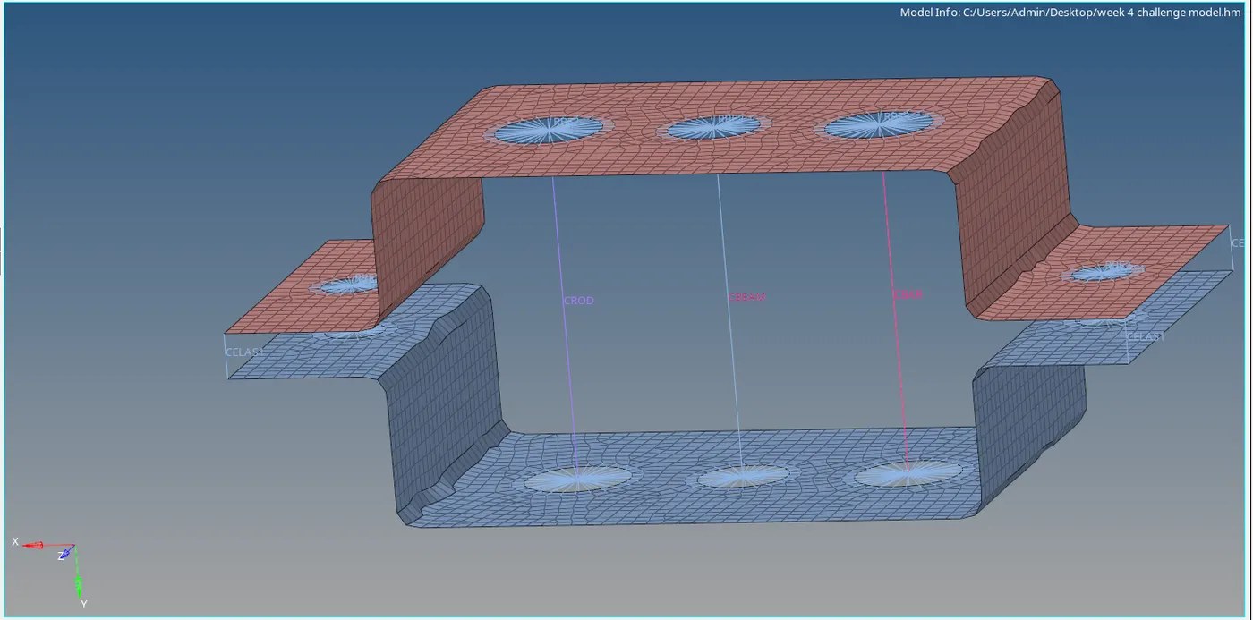
Figure-4(Creating the rod element)
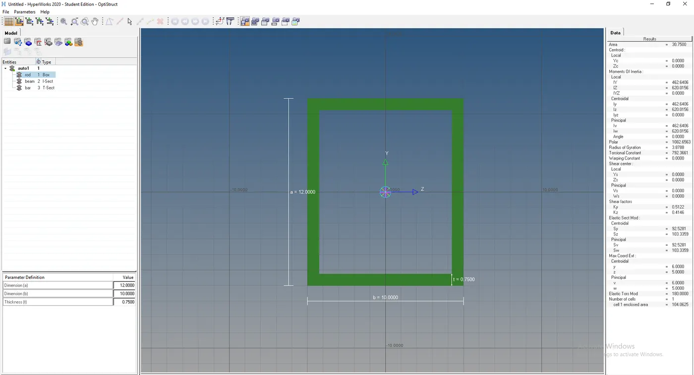
Figure-5( box sectiion in hyperbeam view)
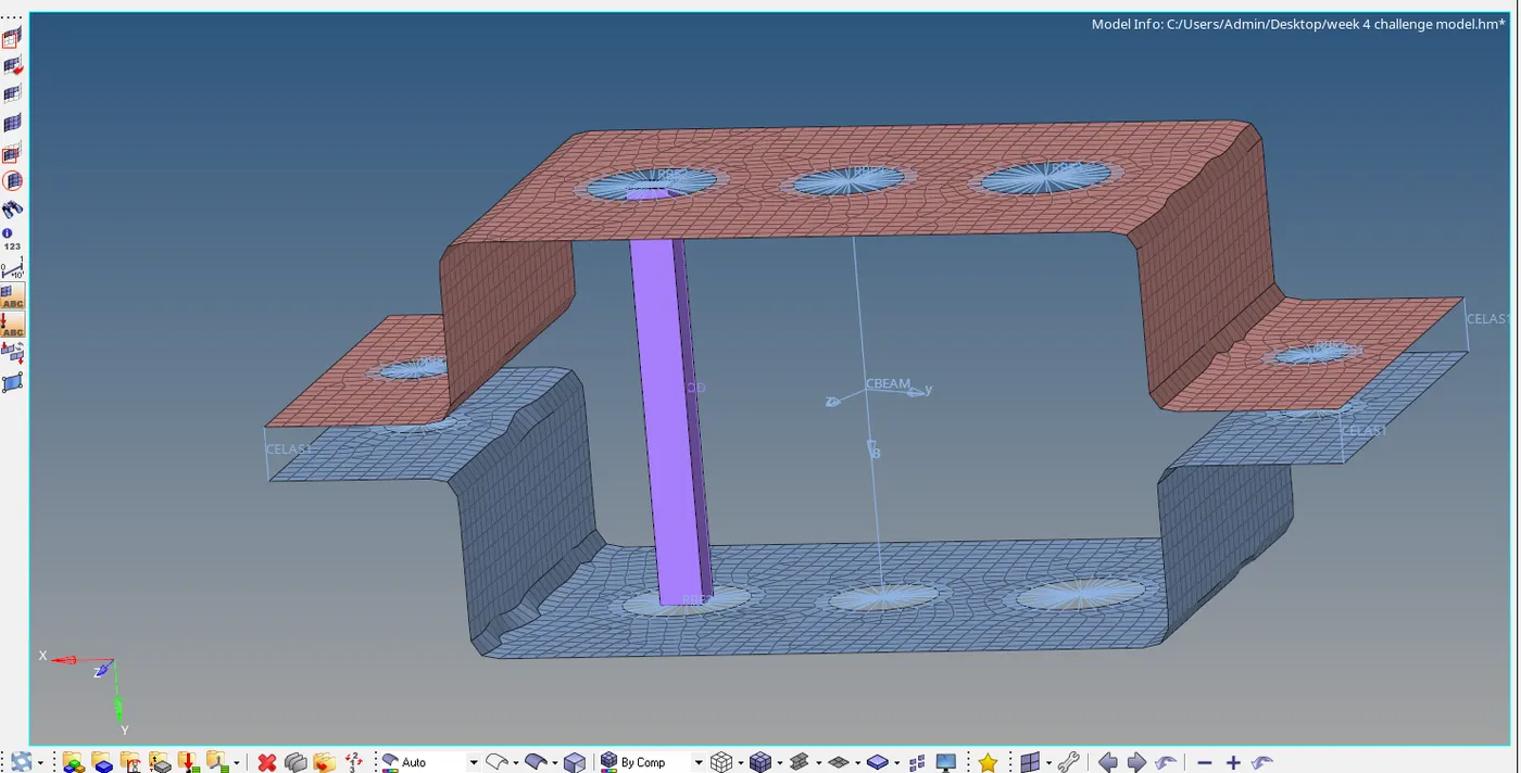
Figure-6(Rod as box cross section)
Beam:
1.Create rbe3 link for 2nd holes by going into 1d option and clicking on rbe3 option.
2.Select the given DOF criteria and click on OK.
3.To create a beam element, click on bars and select element type as"CBEAM".
4.Select the two nodes for beam element and select the cross section nodes.
5.Beam element in 1D is created.
Figure-7(Creating the beam 1d element)
6.To represent it as I section, click on hyperbeam.
7.Select "standard section" and section type as "I" section.
8.In hyperbeam view mention the given parameters and rename it as beam.
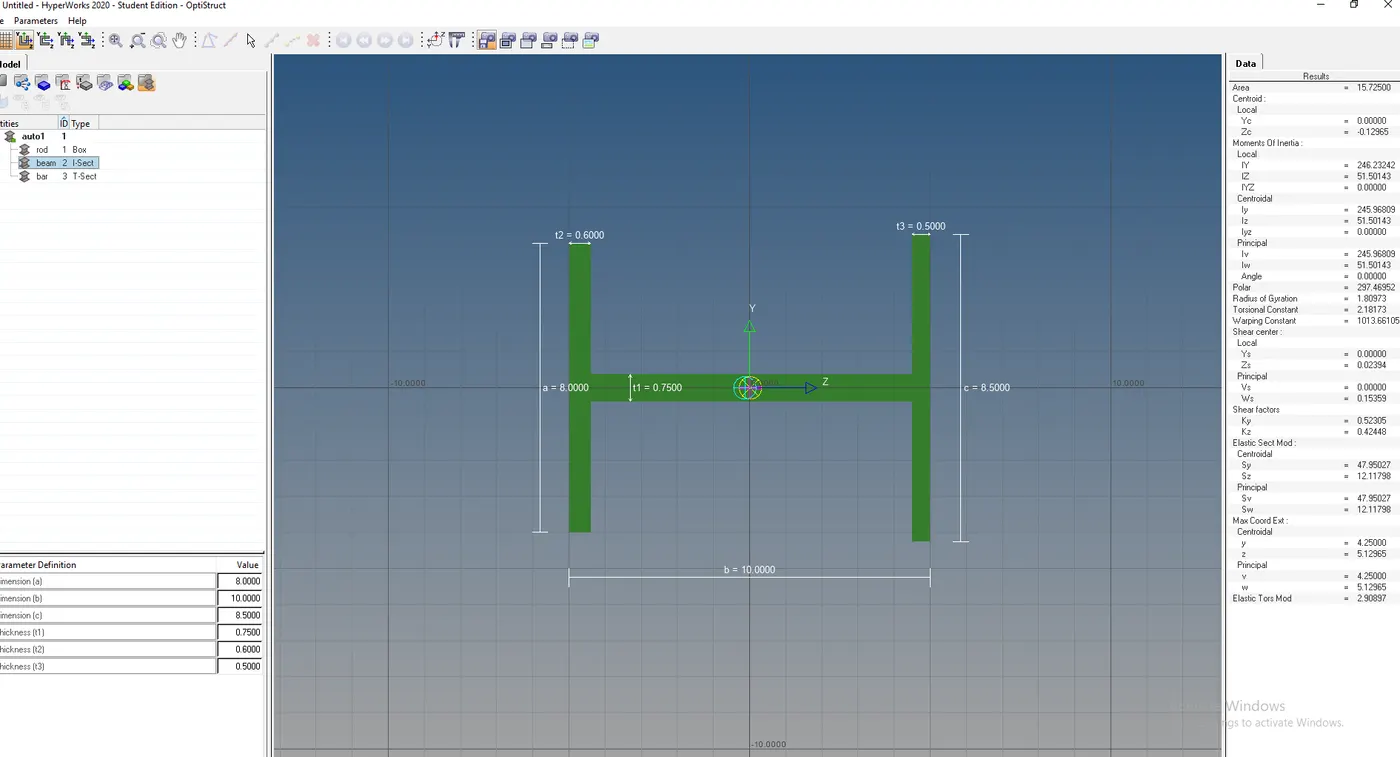
Figure-8(I section in hyperbeam view)
9.Go to beam property id, select the card image as "PBEAM" and beam section as "beam" which is "I"section.
10.Again go to bars,click on update option and select property type as "beam", click on OK.
11.Now go to beam component in toolbar and do right click.
12.Click on "assign", select the beam, click on "apply and then OK.
13.Go to tools option,select "Organise",select the beam element in model and dest component as beam.
14.Click on move and beam is displayed as I section.
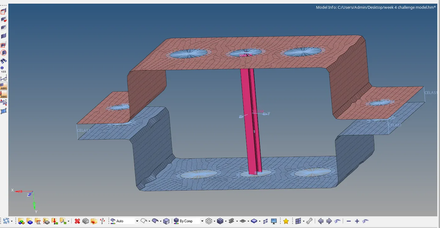
Figure-9(beam as I section)
Bar:
1.Create rbe3 connection by clicking on rbe3 in 1d option.
2.Select the given DOF criteria and and click on OK.
3.For creating bar element, go to bars option and select element type as"CROD".
4. Select the two nodes and cross section nodes and click on OK.
5.Bar is created as 1d element.
Figure-10(bar 1d element)
6.To represent bar element as "cross " section, select the hyperbeam.
7.Click on "standard section and section type as "standard T section" and click create.
8.In hyperbeam view assign the given dimensions and rename it as bar.\
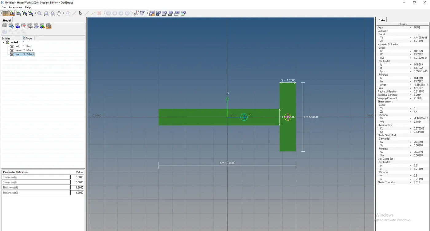
Figure-11(T section hyperbeam view)
9.In bar property id, select the card image as "PBAR" and beam section as "bar".
10.Again go to bar option,click on update and select the property type as "bar" and click on update.
11.Now go to bar component id in toolbar, and perform right click.
12.Click on "assign" , select the property as bar and click on "apply " & "OK".
13.Go to the tool option, click on "Organise" option.
14.Select the element and and dest component as "bar".
15.Click on "move" and bar as T section is displayed.
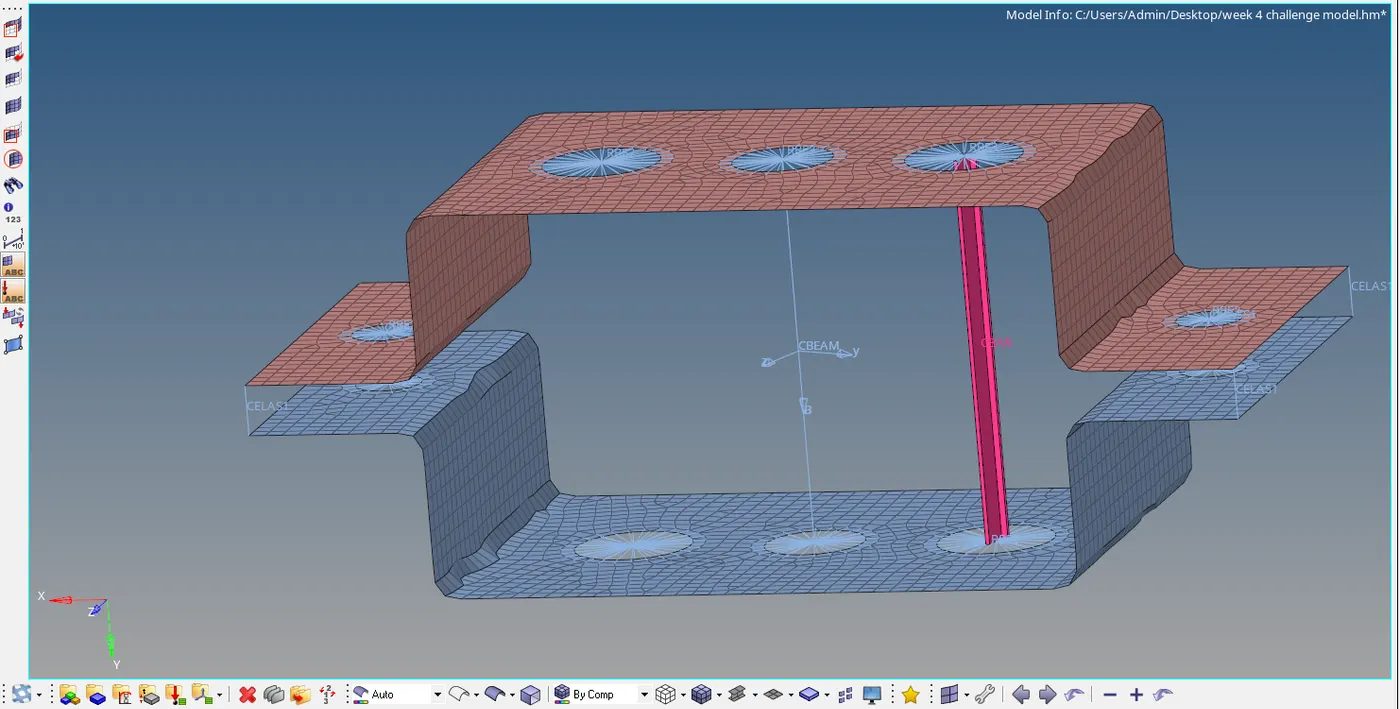
Figure-12(bar as t section)
h.Connect the remaning holes with rbe2 connection.
i.For rbe2 nodes of bracket 1 mass of 10 magnitude is to applied by clicking on masses option.
j.Select the nodes for applying masses and enter the mass value and click on OK.
k.Go to spring option and select the cornes of each bracket.
l.Select the element type as "CELA1" and click on OK.
LEARNING OUTCOME:
Got used to make connections like
- RBE2
- RBE3
- bars
- rods
- springs
- masses
and how to create different cross sections in hyperbeam view.
FINAL OUTCOME:
The connections are made with given cross sections, dimensions and DOF.
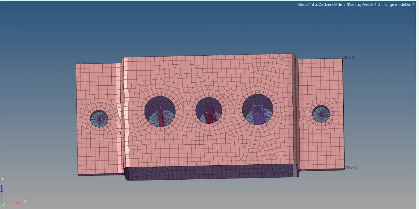
Figure-13(after connections , top view)
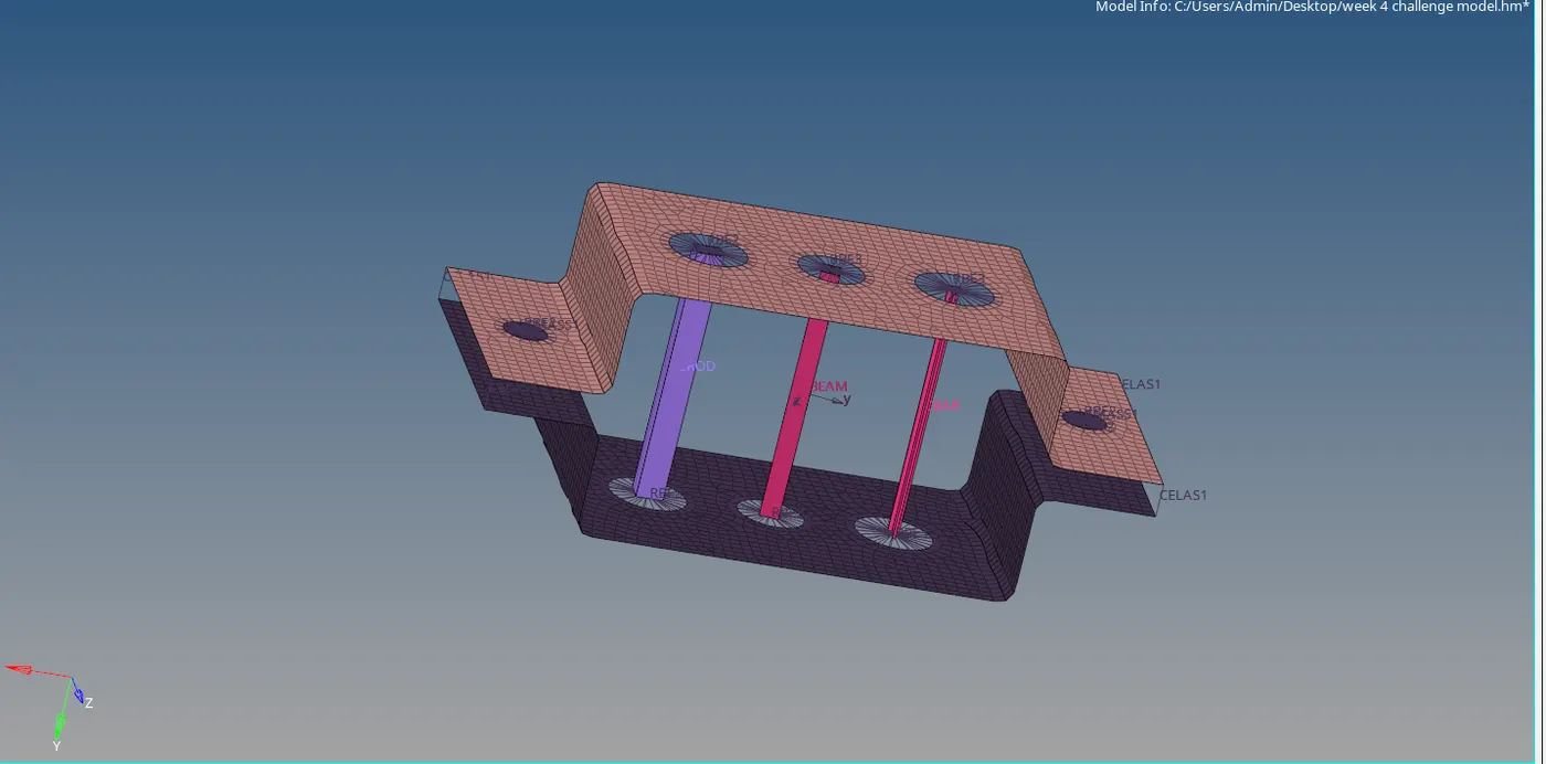
Figure-14(side view)