Control logic for a washing machine and Gear shift
- 1) AIM
- 1.1) Implement control logic of a washing machine using Stateflow
- 1.2) Make a Simulink chart for the “Gear shift”
- 2) OBJECTIVE
- 2.1) Part-1 Control logic for washing machine
- a) With help of stateflow simulate complete operation of a washing machine right from power off to drying and termination of cycle.
- b) The model should be in such a way that if the power supply is available, the system gets activated and if the water supply is not available, the process is terminated and the sameis indicated through LED
- c) The complete cycle time for washing is 370 s which is divided into various operation and each need to be indicated via LED
- d) Soaking time should be 200s followed by Washing time of 100s and then rinsing happens for next 20s and drying for 50s
- 2.2) Part-2 Implement a gear shift logic such that
- a) For each speed range a gear shift is indicated
- Speed Range(kmph) Gear
0 to 15 1
16 to 25 2
26 to 40 3
41 to 60 4
Above 61 5
- b) In real time speed is varied and the change in gear is displayed
- 3) METHOD
- What is control logic and stateflow?
- The different operations in a system can be controlled via what is called as control logic. The input is fed by the user to which the control logic responds by performing automated tasks that have been structured into a program. By form a sequence d)of hierarichal state machines that forms a state diagram a control logic can be modelled. State is the operating mode of a system. State flow is a kind of graphical language made up of states and transitions from one state to another forming a sequential logical system.The transition from one state to another is decided by input.
- 3.1) Washing machine control logic
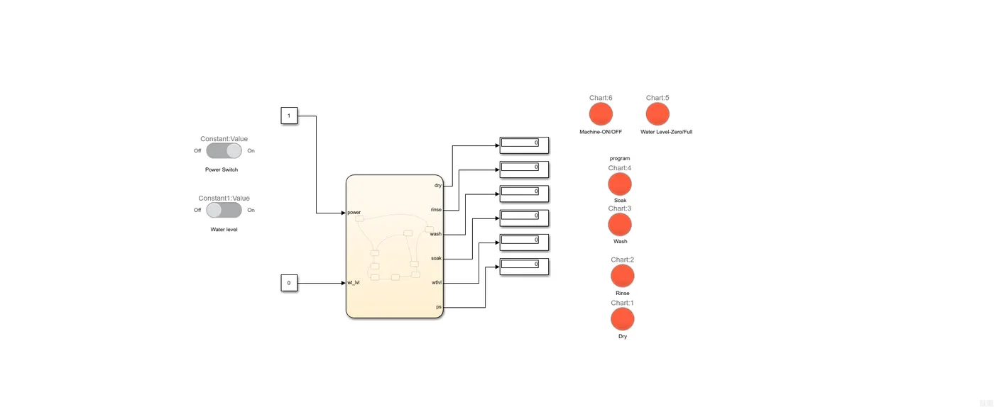
- a) Two inputs are required. One for power for washing machine and other for water supply.
- b) The logic must be modeled in such a way that when both the power and water supply is on the washing machine complete performs complete set of actions from soaking to drying where the operation is terminated.
- c) Two constant blocks are fed to input, both of which are controlled by slider swicth. At 1 it is on and for 0 it is off
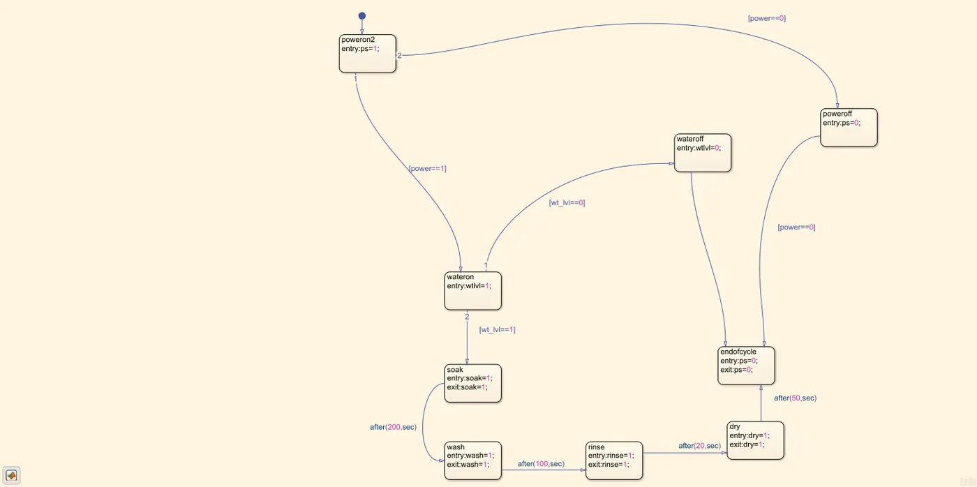
- d) The chart which encloses operations are decipted below along with the overall model
-
-
- e) By slider switch input is set as 1 for on for both water and 0 fof off
- f) With the first state the ouptut is set as one, and a trasntion is made from power on to water check if power is equal to 1. The state goes to wateron if input to wt_lvl is one (transition statement). The output for water check is set as 1 during entry if not transition is and machine goes to off state directly else forward operations are carried out
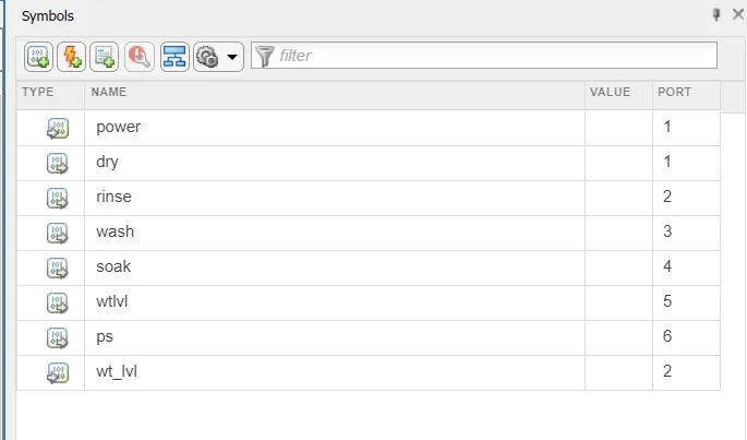
- g) The input and output for the stateflow is defined in symbol pane after making the blocks and defining transition statements as defined below:
-
- h) Each state after check of water input happens for a certain time.
- i) The output for all states namely soak,wash,rinse and dry are set as 1 at entry and exit and for the termination state output is set as 0 at entry at exit.
- j)Transition statement between each states represents the time for which each action happens. All this are given in format of after(time,sec). The time values are soak:200 sec,wash:100 sec,rinse:20 sec,dry:50 sec post which the state end of cycle is given.
- k) LED is used to represent each state of cycle. Total run time = 370 sec
- 3.2) Gear shift
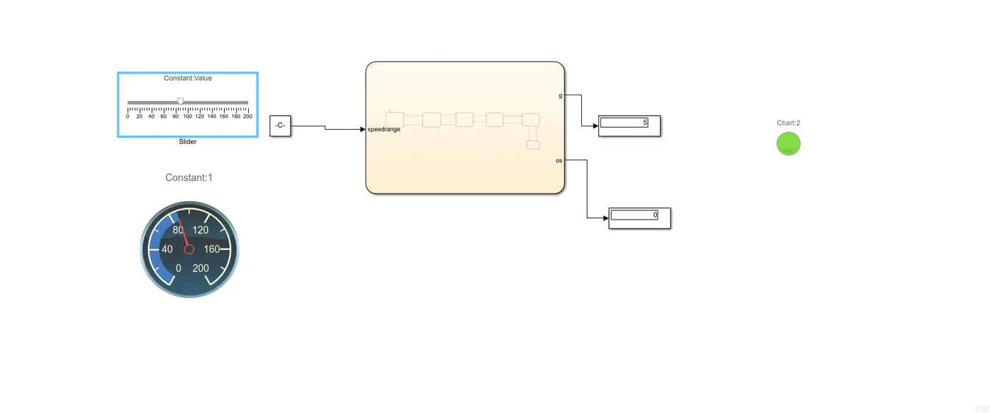
- a) The speed range is the input to the chart which consists of different state each representing different speed limits.
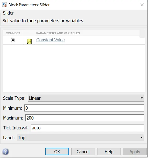
- b) A constant block is fed to input values of which are changed during run time set as inf . The input value is changed using a slider with paramters set as below:
-
- c) The input is also connected to a gauage to show the speed as slider is varied during run time
- d) The model representing the system and chart are decipted below:
-
-
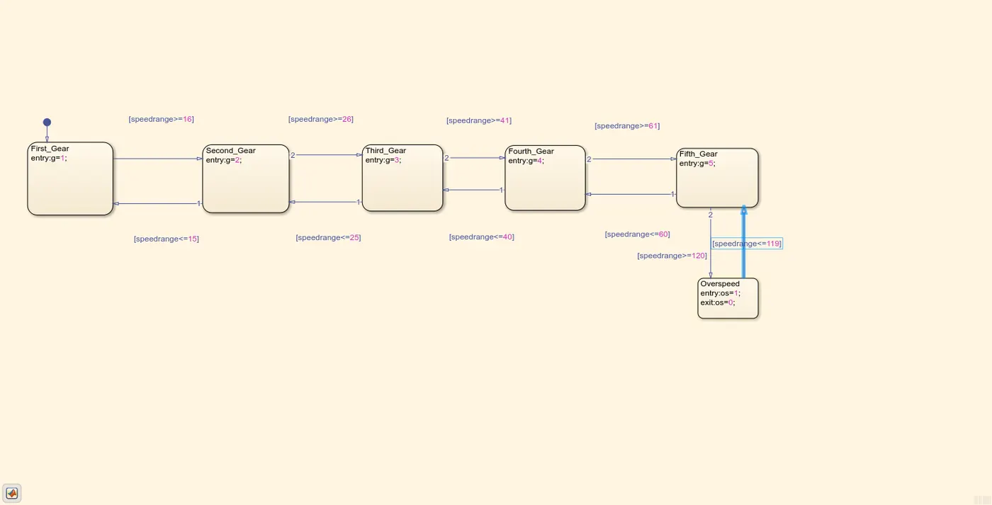
- e) Each states inside chart are named first gear,second gear on till fifth gear.
- f) Since the output to be displayed is gear postion as speed changes the output staments inside all block till gear 1 to gear 5 are given output values to 1 to 5. The transition statements happen to speed on which a gear is shifted from one to another. The transition statements are based on speedrange which is set as input. The transition statements are shown below:
-
Speed Range(kmph) Gear Transition statement
0 to 15 1 1-2=speedrange>=16; 2-1=speedrange<=15
16 to 25 2 2-3=speedrange>=2; 3-2=speedrange<=25
26 to 40 3 3-4=speedrange>=41;4-3=speedrange<=40
41 to 60 4 4-5=speedrange>=61;5-4=speedrange<=60
Above 61 5 4-5=speedrange>=61
- Overspeed speedrange>=120
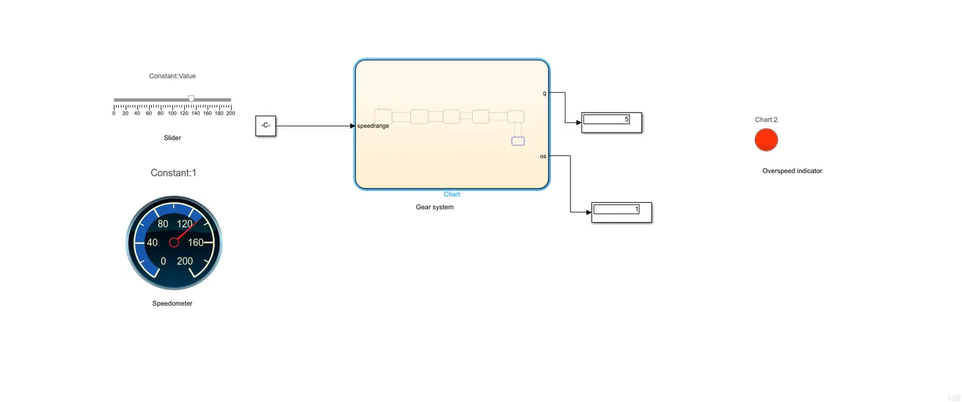
- g) Another state called as over speed is defined which senses if vehicle as exclalated beyond a particular speed. Its output at entry is 1 and and exit is 2. An LED is used to sense the overspeed
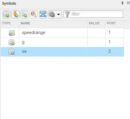
- h) The variables are defined in symbol pane as below:
-
4) OUTPUT
- 4.1) Part 1 Washing machine control logic
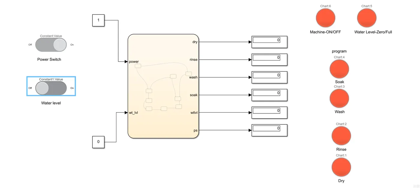
- a) Power input to machine is on but water input to machine is off. This is because after first state machine power is checked, found on but when water is zero it is connected to operation termination
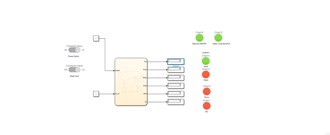
- b)Power input to machine is on but water input to machine is on. Display shows 1 for power,water level as well as soak. The run time is 200s. After 200s the machine finished soaking operation
-
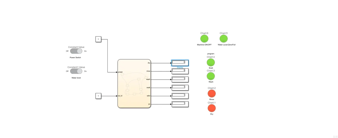
- c) Power input to machine is on but water input to machine is on. Display shows 1 for power,water level,soak as wash. The run time is 300s. After 300s the machine would have finished washing operation
-
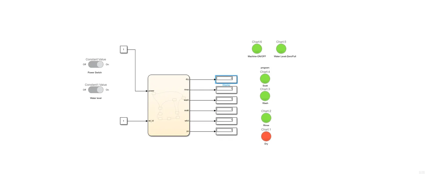
- d )Power input to machine is on but water input to machine is on. Display shows 1 for power,water level,soak wash and rinse. The run time is 320s. After 300s the machine would have finished washing operation
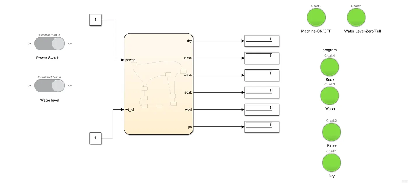
- e) Both power input and water input is on and the machine is run for 370 sec. ( dryer state). Process is finished
-
- 4.2) Part 2 Gear shift logic
- a) The slider is moved with run time as infinity.
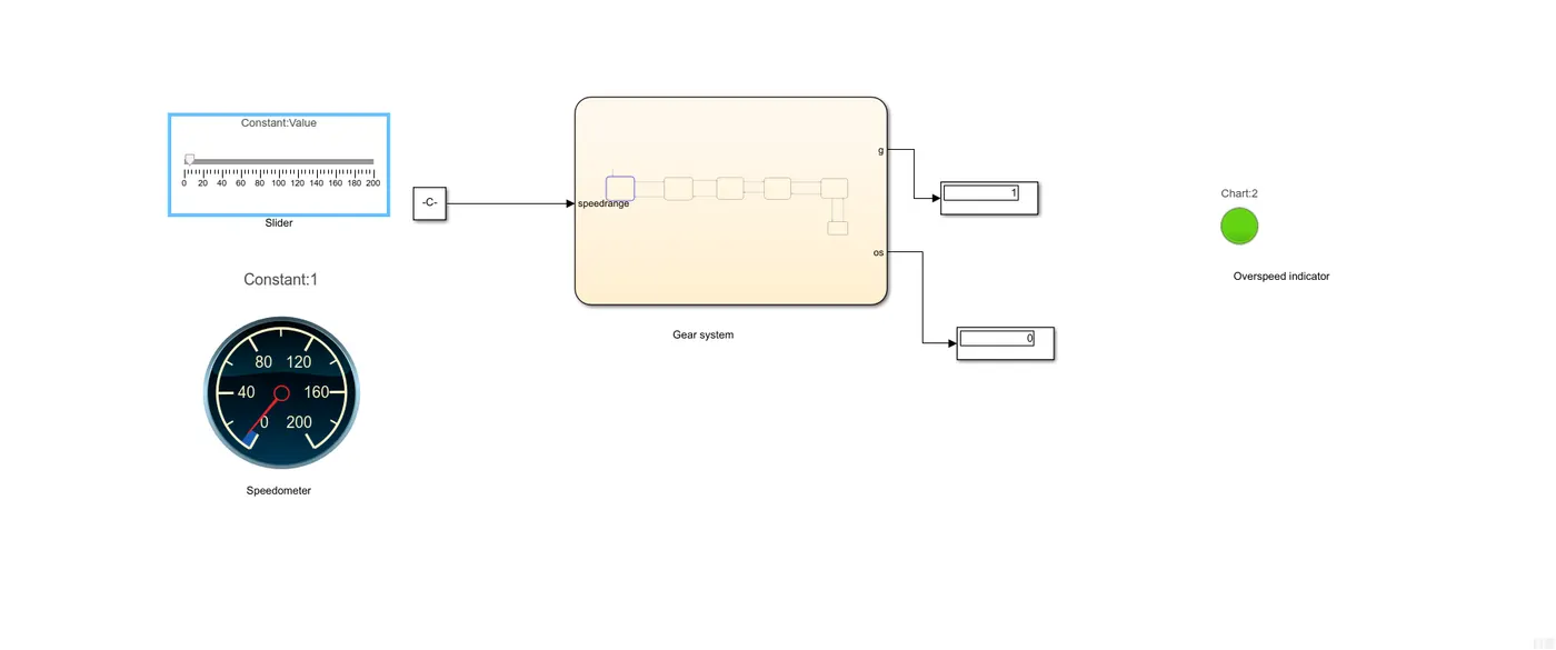
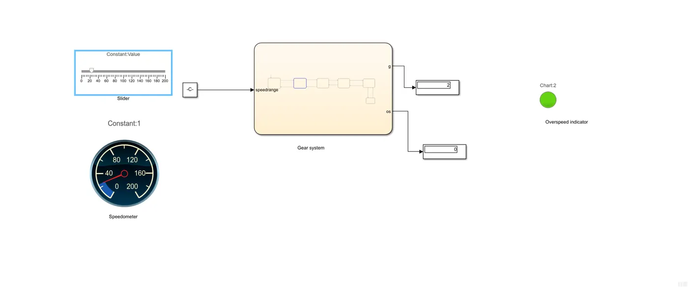
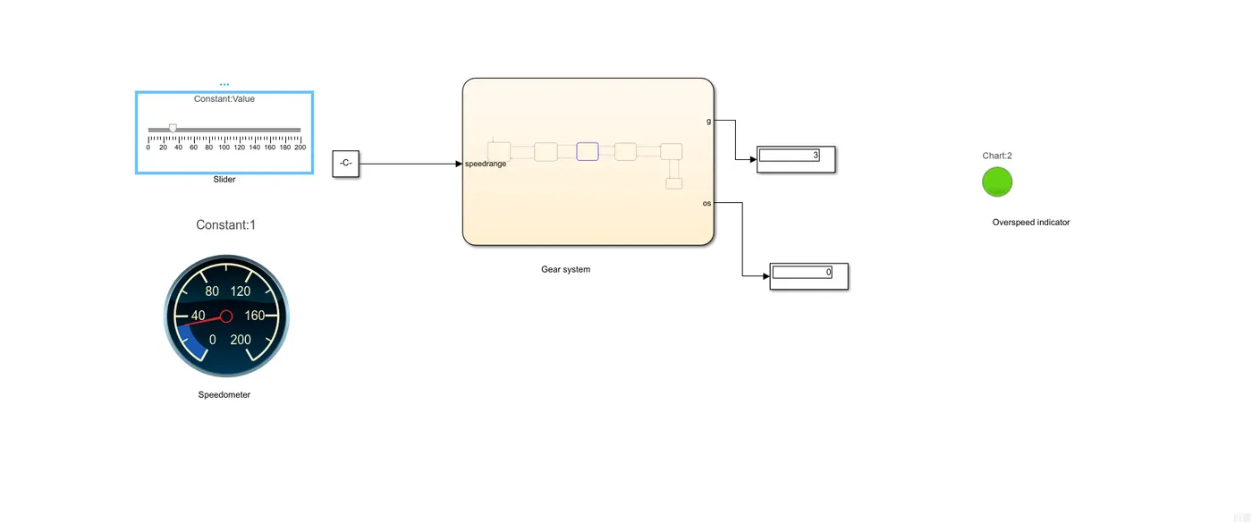
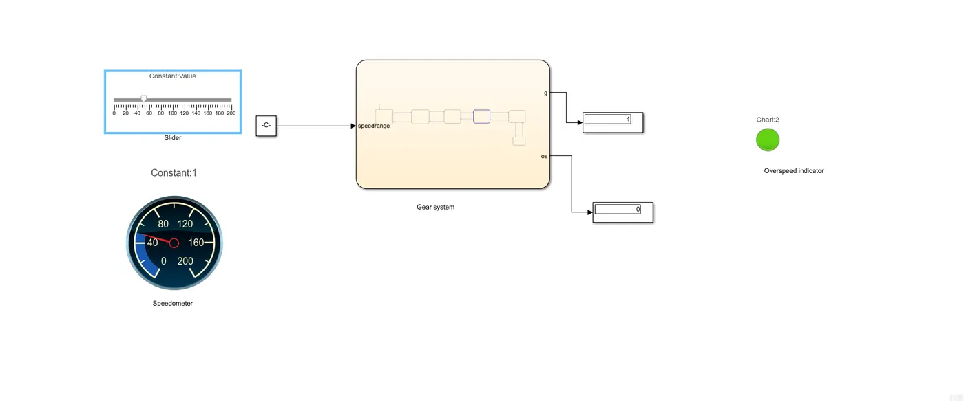
- b) The different output according to slider position reflect in display
- Gear 1 when speed is below 15 km/hr
-
- Gear 2 when speed is between 16-25 km/hr
-
- Gear 3 when speed is between 26-40 km/hr
- Gear 4 when speed is between 41-60 km/hr
- Gear 5 when speed is above 60km/hr
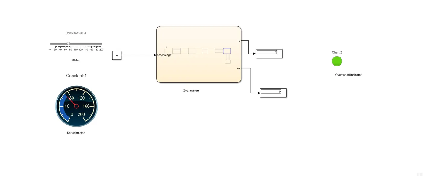
- When speed is above 120 km/hr it is termed as overspeed and indicated with a red light
- 5) Inference
- The stateflow is entirely dependant on input,output and transition statements. For a smooth control flow it is essential to define what inputs and outputs are in symbol pane.