Automatic Gear Shift Control using Stateflow
Q1. Create a Simulink chart for the “Gear shift” logic
Input
| Speed Range | Gear |
| 0 to 15 | 1 |
| 16 to 25 | 2 |
| 26 to 40 | 3 |
| 41 to 60 | 4 |
| Above 61 | 5 |
Transmission System
A transmission is a machine in a power transmission system, which provides controlled application of the power. Often the term 5-speed transmission refers simply to the gearbox that uses gears and gear trains to provide speed and torque conversions from a rotating power source to another device.
The term transmission refers to the whole drivetrain, including clutch, gearbox, prop shaft (for rear-wheel drive), differential, and final drive shafts. The most common use is in motor vehicles, where the transmission adapts the output of the internal combustion engine to the drive wheels. Such engines need to operate at a relatively high rotational speed, which is inappropriate for starting, stopping, and slower travel. The transmission reduces the higher engine speed to the slower wheel speed, increasing torque in the process. Transmissions are also used on pedal bicycles, fixed machines, and where different rotational speeds and torques are adapted.
A transmission has multiple gear ratios (or simply "gears") with the ability to switch between them as speed varies. This switching may be done manually (by the operator) or automatically. Directional (forward and reverse) control may also be provided. Single-ratio transmissions also exist, which simply change the speed and torque (and sometimes direction) of motor output.
Single Stage Gear Reducer
The relation between gear and velocity
Gear teeth are designed so the number of teeth on a gear is proportional to the radius of its pitch circle, and so the pitch circles of meshing gears roll on each other without slipping. The speed ratio for a pair of meshing gears can be computed from the ratio of the radii of the pitch circles and the ratio of the number of teeth on each gear.
The velocity `v` of the point of contact on the pitch circles is the same on both gears and is given by
`v=r_aw_a=r_bw_b`
where input gear A with radius `r_a` and angular velocity `w_b` meshes with output gear B with radius `r_b` and angular velocity `w_b`. Therefore,
`w_a/w_b=r_b/r_a=N_b/N_a`
where `N_a` is the number of teeth on the input gear and `N_b` is the number of teeth on the output gear.
The mechanical advantage of a pair of meshing gears for which the input gear has `N_a` teeth and the output gear has `N_b` teeth is given by
Mechanical Advantage=`N_b/N_a`
This shows that if the output gear GB has more teeth than the input gear GA, then the gear train amplifies the input torque. And, if the output gear has fewer teeth than the input gear, then the gear train reduces the input torque.
If the output gear of a gear train rotates more slowly than the input gear, then the gear train is called a speed reducer. In this case, because the output gear must have more teeth than the input gear, the speed reducer amplifies the input torque.
Blocks Used
1. Chart
A finite state machine is a representation of an event-driven (reactive) system. In an event-driven system, the system responds to an event by making a transition from one state (mode) to another. This transition occurs if the condition defining the change is true.
2. Display
The Display block shows the value of the input data. You can specify the frequency of the display. For numeric input data, you can also specify the format of the display.
3. Constant
The Constant block generates a real or complex constant value signal. Use this block to provide a constant signal input.
4. Lamp
The Lamp block displays a color indicating the value of the input signal. You can use the Lamp block with other Dashboard blocks to build an interactive dashboard of controls and indicators for your model. You can specify pairs of input values and colors to provide the information you want during the simulation.
5. Slider
The Slider block tunes the value of the connected block parameter during the simulation. For example, you can connect the Slider block to a Gain block in your model and adjust its value during the simulation. You can modify the range of the Slider block's scale to fit your data. Use the Slider block with other Dashboard blocks to create an interactive dashboard to control your model.
Logic Explanation
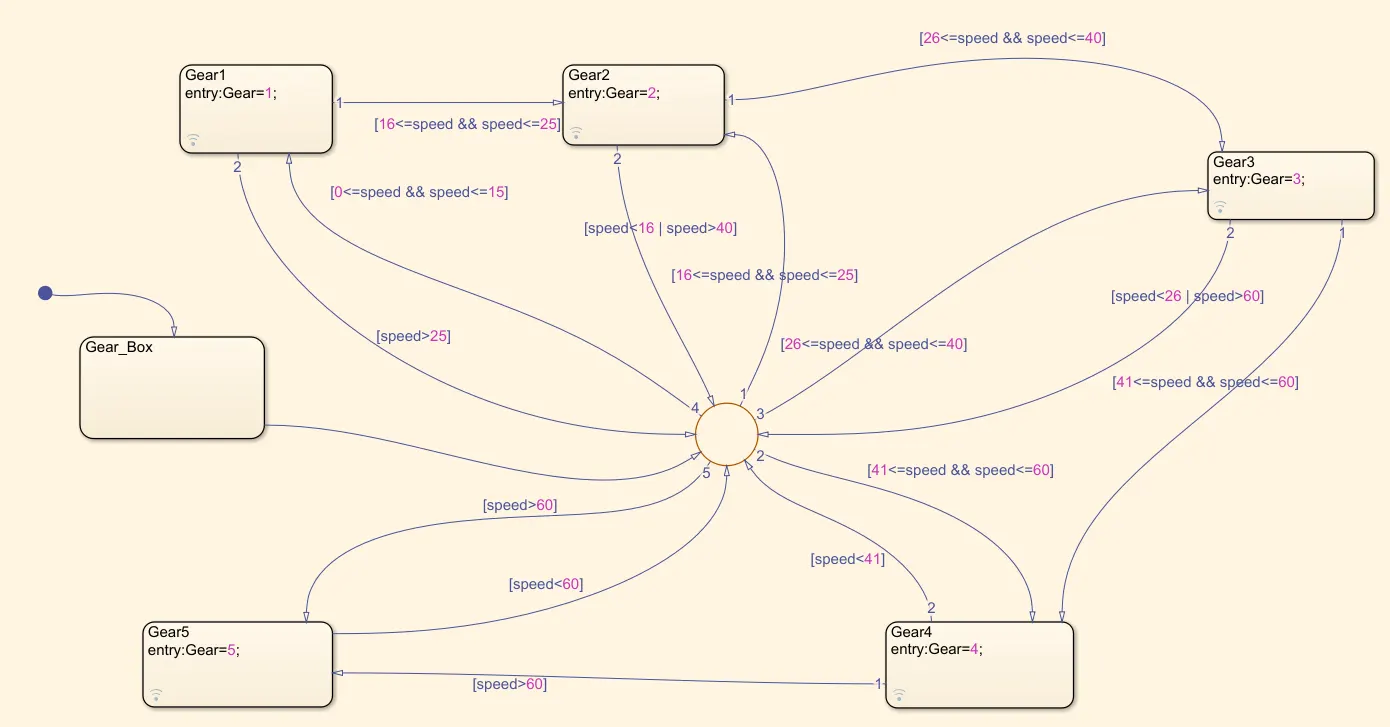
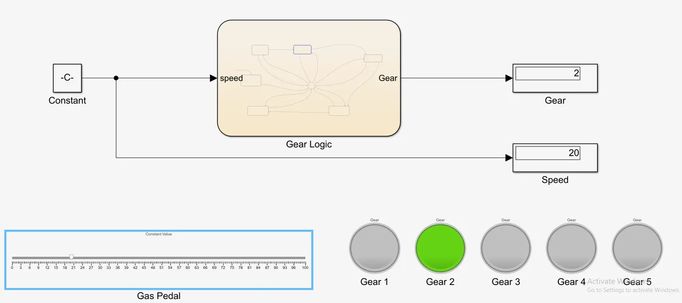
The speed ranges from 0 to 100 and the slider is used to send the input. The 1st gear has speed values from 0 to 15 so the entry condition for the 1st gear is 0<=speed and speed<=15 and the exit condition is when the speed greater than 15. Similarly for 2nd gear, the entry condition is 16<=speed and speed<=25 ana the exit condition is when speed<16 and speed>25. In the same way for each gear, the entry and the exit condition are specified and the out is mapped to the lamp and the display block. A junction block is used between all the states and for easy input signal communication.
Logic
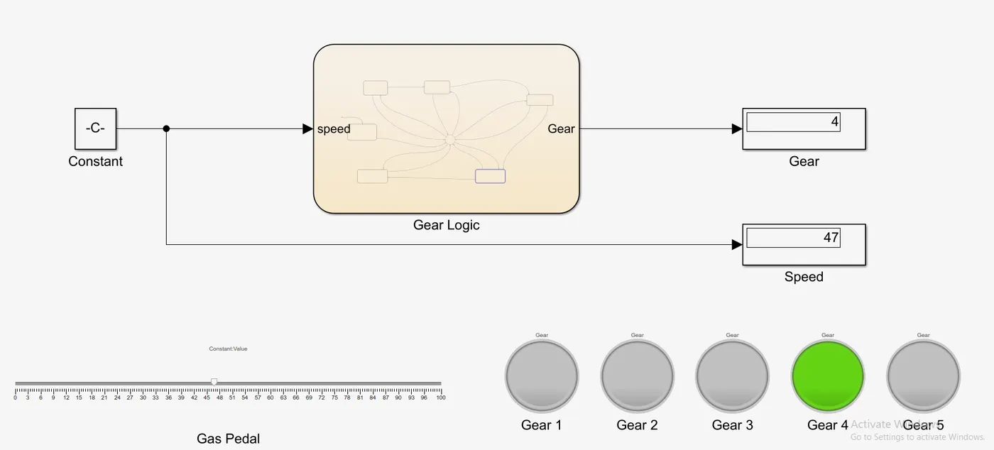
Simulink Model at different speeds
At Speed=47
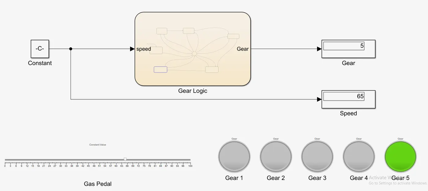
At Speed=65
At Speed=20
Q2. Implement control logic of a “washing machine” using Stateflow
Inputs Given
- If the power supply is available, the system gets activated.
- If the Water supply is not available, stop the process & indicate through the LED.
- Soaking time should be 200s followed by Washing time of 100s.
- Then rinsing happens for the next 20s & the dryer runs for the 50s.
Washing Machine
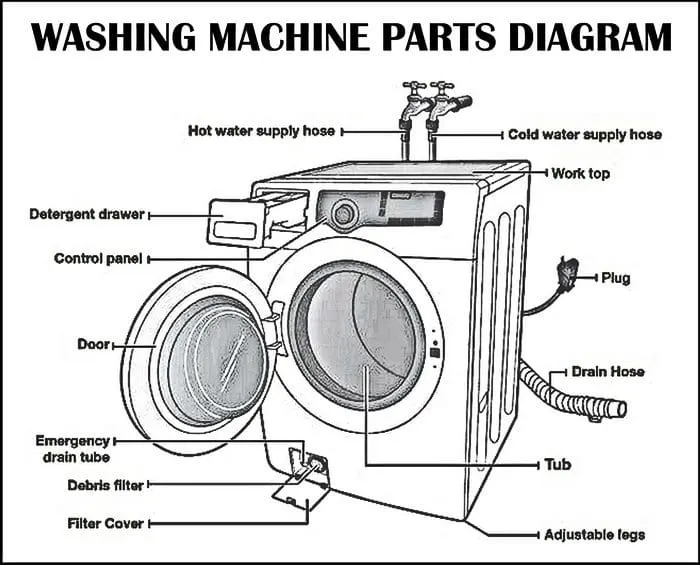
All the important parts of the clothes washer are electrically controlled, including the inner drum, the valves, the pump, and the heating element. The program switching these things on and off in a sensible sequence that goes something like this:
1. You put your clothes in the machine and detergent either in the machine itself or in a tray up above.
2. You set the program you want and switch on the power.
3. The programmer opens the water valves so hot and cold water enter the machine and fill up the outer and inner drums. The water usually enters at the top and trickles down through the detergent tray, washing any soap there into the machine.
4. The programmer switches off the water valves.
5. The thermostat measures the temperature of the incoming water. If it's too cold, the programmer switches on the heating element. This works just like an electric kettle or water boiler.
6. When the water is hot enough, the programmer makes the inner drum rotate back and forth, sloshing the clothes through the soapy water.
7. The detergent pulls the dirt from your clothes and traps it in the water.
8. The programmer opens a valve so the water drains from both drums. Then it switches on the pump to help empty the water away.
9. The programmer opens the water valves again so clean water enters the drums.
10. The programmer makes the inner drum rotate back and forth so the clean water rinses the clothes. It empties both drums and repeats this process several times to get rid of all the soap.
11. When the clothes are rinsed, the programmer makes the inner drum rotate at a really high speed—around 80 mph (130 km/h). The clothes are flung against the outside edge of the inner drum, but the water they contain is small enough to pass through the drum's tiny holes into the outer drum. Spinning gets your clothes dry using the same idea as a centrifuge.
12. The pump removes any remaining water from the outer drum and the wash cycle comes to an end.
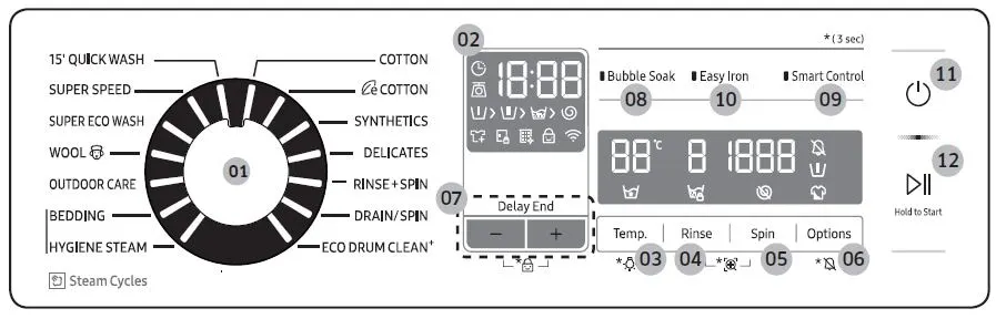
Modern Washing Machine Panel
Blocks Used
1. Chart
A finite state machine is a representation of an event-driven (reactive) system. In an event-driven system, the system responds to an event by making a transition from one state (mode) to another. This transition occurs if the condition defining the change is true.
2. Display
The Display block shows the value of the input data. You can specify the frequency of the display. For numeric input data, you can also specify the format of the display.
3. Constant
The Constant block generates a real or complex constant value signal. Use this block to provide a constant signal input.
4. Lamp
The Lamp block displays a color indicating the value of the input signal. You can use the Lamp block with other Dashboard blocks to build an interactive dashboard of controls and indicators for your model. You can specify pairs of input values and colors to provide the information you want during the simulation.
5. Toggle Switch
The Toggle Switch block toggles the value of the connected block parameter between two values during simulation. For example, you can connect the Toggle Switch block to a Switch block in your model and change its state during the simulation. Use the Toggle Switch block with other Dashboard blocks to create an interactive dashboard for your model.
6. Slider Switch
The Slider Switch block toggles the value of the connected block parameter between two values during simulation. For example, you can connect the Slider Switch block to a Switch block in your model and change its state during the simulation. Use the Slider Switch block with other Dashboard blocks to create an interactive dashboard for your model.
Logic Explanation
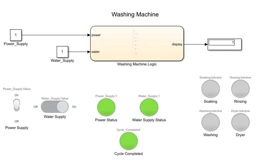
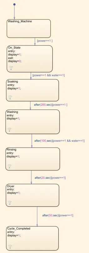
A toggle switch from the dashboard library is used with a constant to supply the power and a lamp is used to indicate the power status. Similarly, a slider from the dashboard library is used with a constant as water supply and a lamp is used to indicate the water status. The power status is checked at the entry for every state and the water supply is checked for the soaking and the rinsing process. The timing for each state is as per the given inputs. The Cycle Button will glow when the cycle completes and the status of the running process can be seen by the glowing lamp corresponding to the process name.
Washing Machine Logic
Cycle Showing the that current process running is drying.
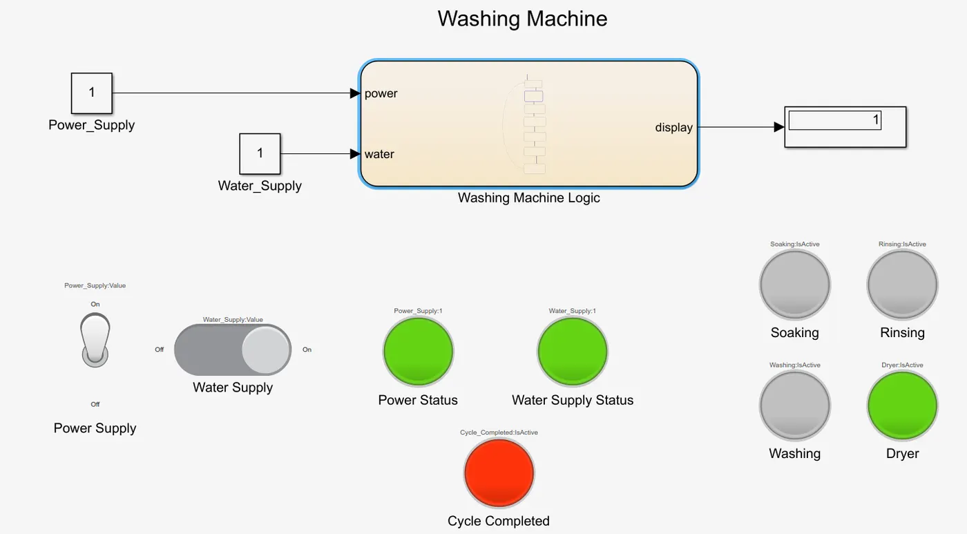
Complete Simulink Model, Showing that the washing process is completed.