Week - 4
QUESTION-1
AIM : Implement control logic of a “washing machine” using Stateflow as per given sequence:
- If the power supply is available, the system gets activated
- If the Water supply is not available, stop the process & indicate through LED
- Soaking time should be 200s followed by Washing time of 100s.
- Then rinsing happens for next 20s & dryer runs for 50s
PROCEDURE: In a washing machine, there are 4 processes Soak, Wash, Rinse, Spin/Dry. For the given conditions washing machine must soak for 200 sec, wash for 100 sec, rinse for 20 sec, spin/dry for 50 sec.
But also if there is no water supply the process must stop, and at no power the washing should not switch on.
To achieve this we use the following blocks and a state flow chart:
- Lamps
- Constants
- Slider switchs
- State flow charts
- Display
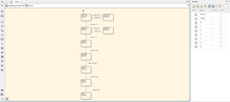
STATEFLOW :
SIMULINK BLOCK : Power & water is off.
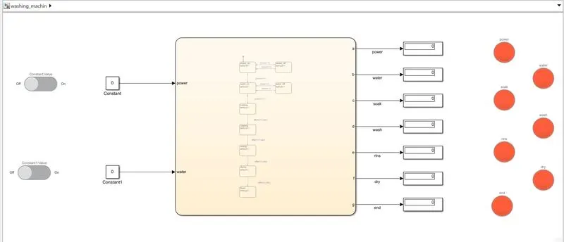
Power is on & water is off.
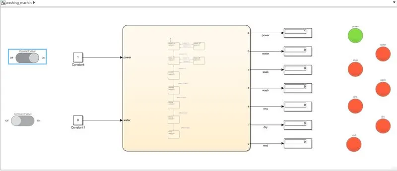
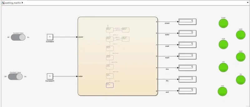
Power & water is on.
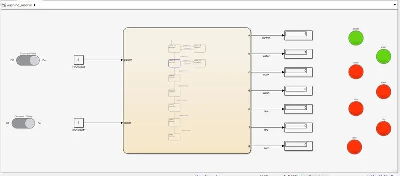
Socking
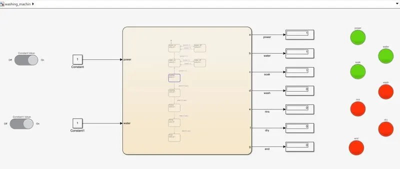
Washing
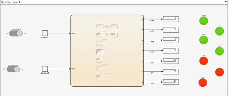
Rinsing
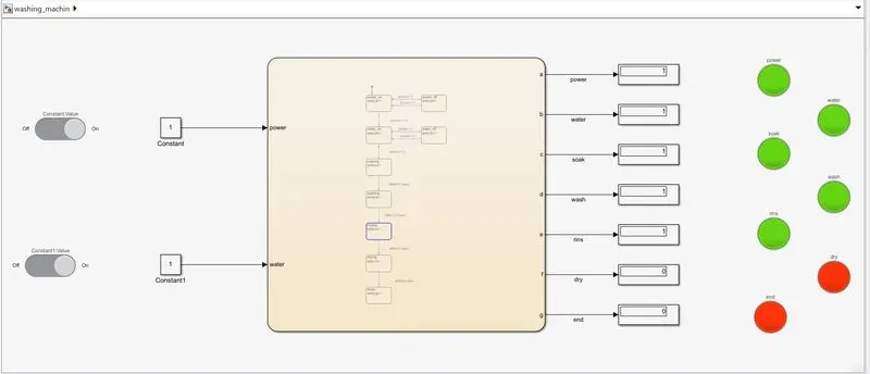
Drying
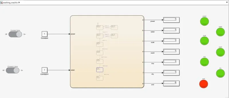
After completion of all process end display is on.
QUESTION-2
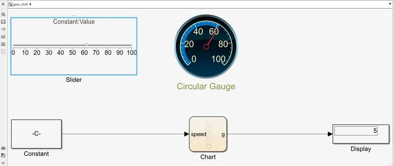
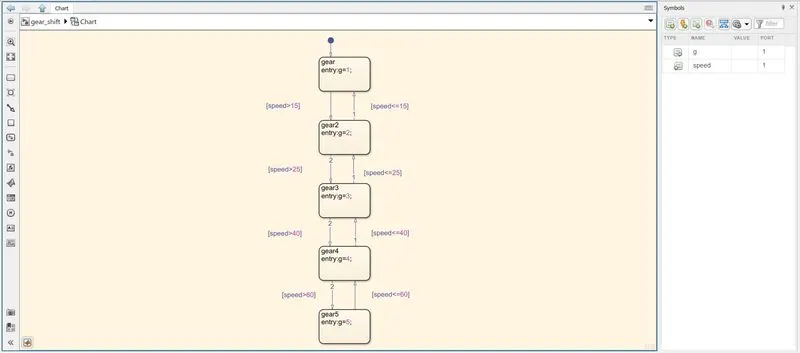
AIM : Make a Simulink chart for the “Gear shift” logic as per below conditions:
Speed Range(kmph) Gear
0 to 15 1
16 to 25 2
26 to 40 3
41 to 60 4
Above 61 5
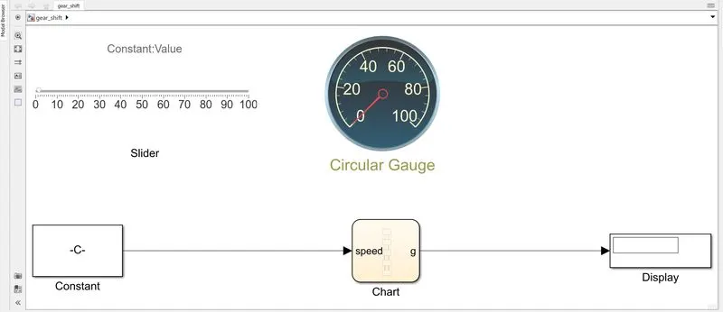
Blocks used:
1. Constant
2. Slider
3. Display
4. State flow chart
5. Circular gauge
State Flow :
Simulink Block :
Output :
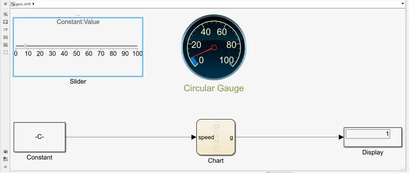
Speed 0 to 15
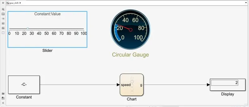
Speed greater than 15 to 25
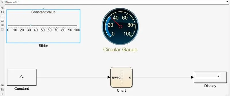
Speed greater than 25 to 40
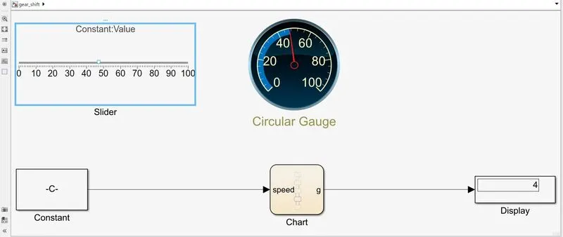
Speed greater than 40 to 60
Speed greater than 60