Week - 4
Aim : To Implement logic control of a Washing Machine Using State Flow As per Sequence
| CONDITION | POWER SUPPLY | WATER SUPPLY | TIME(Sec) | PROCESS |
| 1 | ON | ON | ACTIVE | |
| 2 | ON | OFF | STOP PROCESS,LED IS RED | |
| 3 | ON | ON | 200 | SOAK(LED:GREEN) |
| 4 | ON | ON | 300 | WASH(LED:GREEN) |
| 5 | ON | ON | 320 | RINSE(LED:GREEN) |
| 6 | ON | ON | 370 | DRY(LED:GREEN) |
| 7 | ON | ON | AFTER 370 | FINISHED(LED:GREEN) |
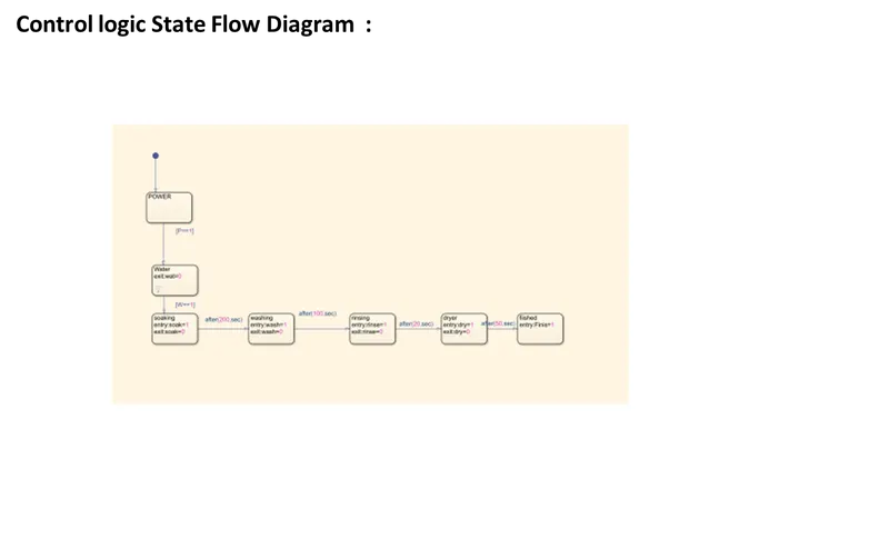
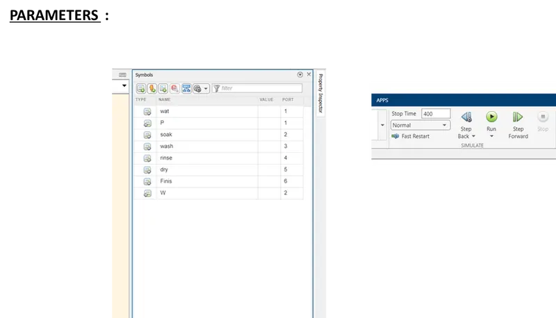
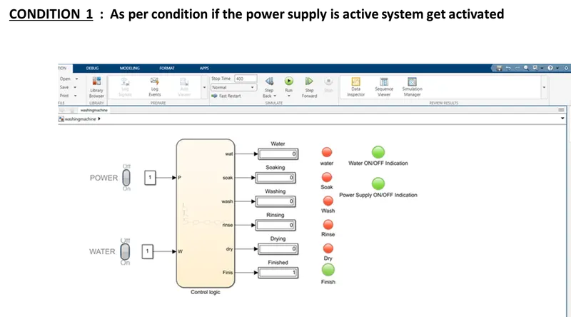
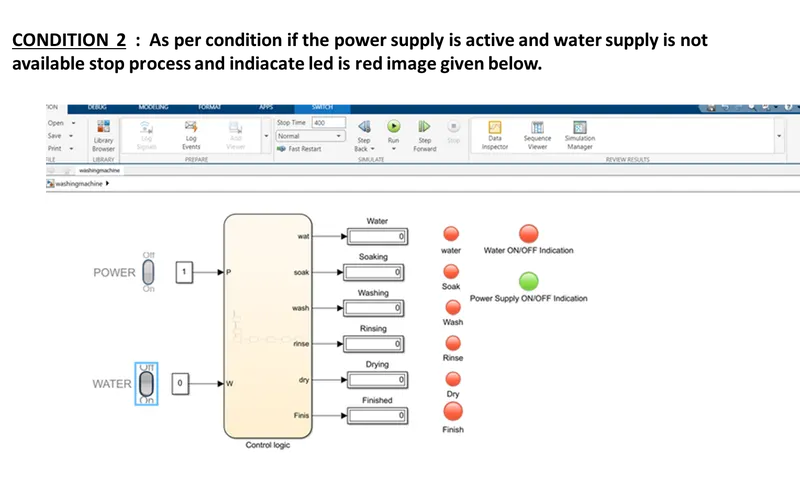
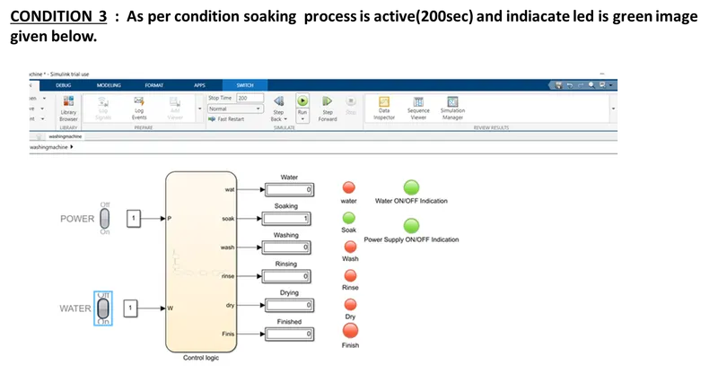
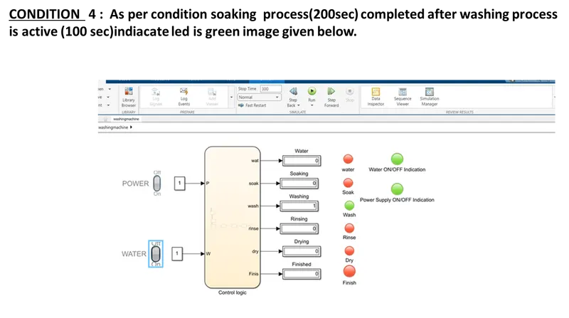
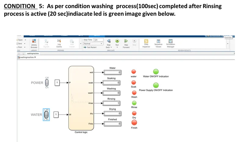
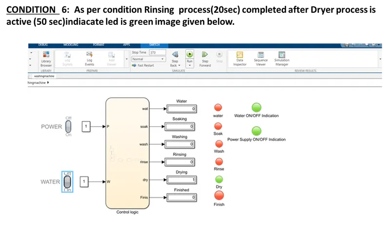
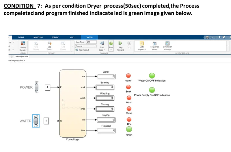
: The control logic of Washing machine using stateflow was implemented and executed successfully as per given sequence
2.
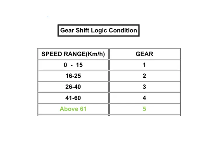
AIM : To Make a Simulink chart for the “Gear shift” logic as per below conditions:
Blocks used in design Simulink model:
1. CHART :
MATLAB State flow chart is a graphical representation of finite state machine, instead of creating script we can use block to know the process or the state of operation
2.SLIDER :
The Slider block tunes the value of the connected block parameter during simulation.
3.CONSTANT :
The constant block is used for input to slider gain is activated.
4.SLIDER GAIN :
The Slider block tunes the value of the connected block parameter during simulation.
5.DISPLAY :
Display is used here to indicate which gear was engaged with the transmission system.
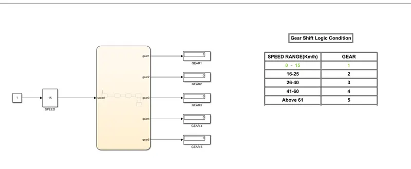
As per 1 st Condition Speed Reached 0 to 15 km per hour Gear 1 engaged.image given below
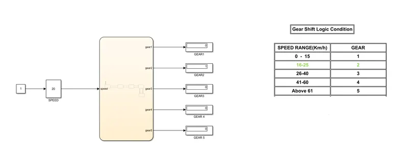
As per 2 nd Condition Speed Reached 16 to 25 km per hour Gear 2 engaged.image given below
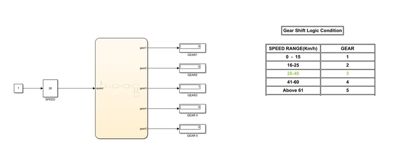
As per 3 rd Condition Speed Reached 26 to 40 km per hour Gear 3 engaged.image given below
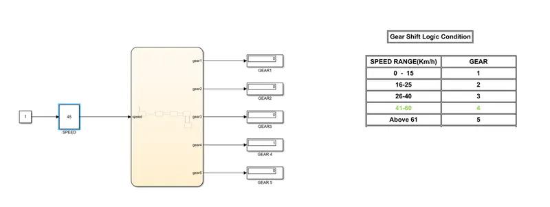
As per 4 th Condition Speed Reached 41 to 60 km per hour Gear 4 engaged.image given below
As per 5 th Condition Speed Reached Above 61 km per hour Gear 5 engaged.image given below
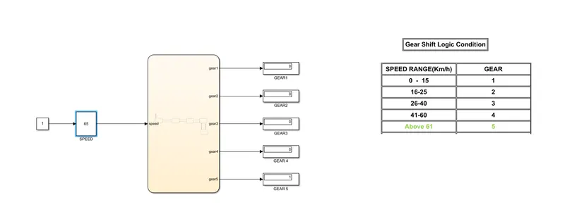
Result : As per given speed input while the simulation is running, and the gear indication was indicated through lamp and display given model was Verified and Validated Successfully.