Project 1 - Controlling a DC motor using PWM and monitoring its Running status
AIM :
To Implement a system on the simulator for controlling a DC motor using L293 motor driver, monitor its status and print the running status of motor on the LCD Display.
Goals:
- We Implement a system on simulator for Controlling the DC motor using L293 motor driver.
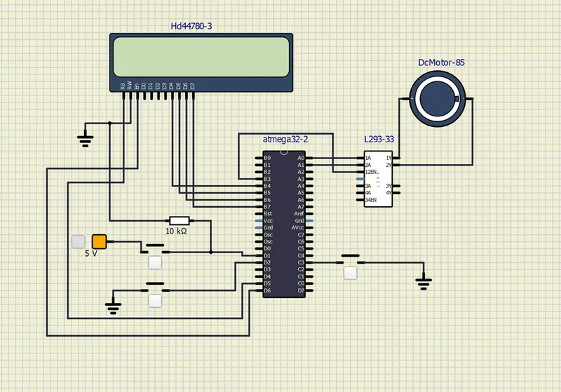
- Displaying the running status of DC motor on the LCD display shown below image.
Key Highlights of the Project:
- The DC motor can be controlled by using L293 motor driver.
- The speed of a DC motor can be controlled by varying its input voltage, for doing this is to use PWM (Pulse Width Modulation).
- L293D IC is a typical Motor Driver IC which allows the DC motor to drive on any direction.(Clockwise or Anticlockwise).
Components :
1.ATmega32 IC
2.2*16 LCD Display(HD44780)
3.DC Motor(12V)
4.Resistor(10kilo ohm)
5.L293 Motor Driver
6.Voltage Source
7.Push Button
8.Ground.
L293 Motor Driver :
In L293 Motor Driver Pin 1A and 2A terminals decide the direction of rotation of the dc motor.To input the 1,0 these pins respectively drive the motor in clockwise direction.And 0,1 responcible for the anticlockwise direction.1,1 or 0,0 has no turning effect.1Y and 2Y terminals are to be connected to the terminals of de motor.
Enable pins are also used control the speed of the dc motor.if you apply PWM signal to these enables pins then the motor driver IC L293 D can control the speed of both motors.
Diagram :
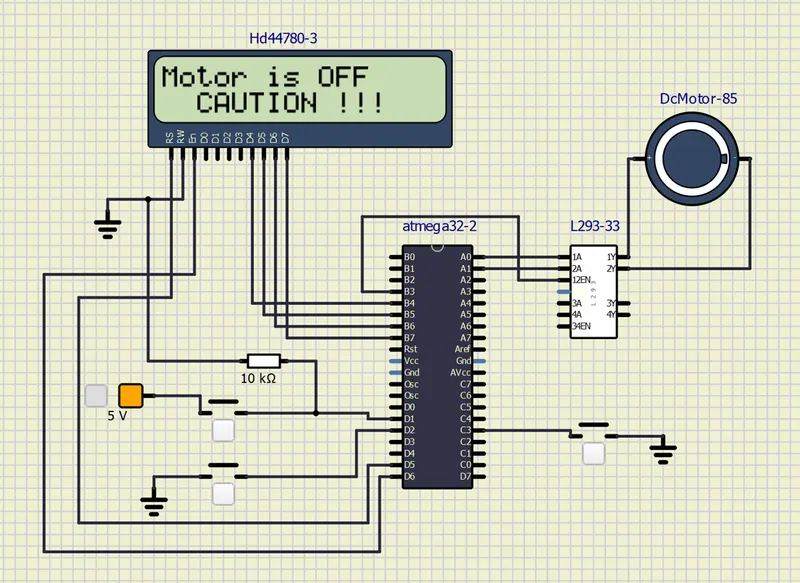
- Lcd Display D4-D7 Pin Connected in Atmega32 IC B4-B7 Pin.
- Port B and Port B B3 pin connected to L293 12EN for enable the Driver
- Port B A0,A1 pins connected to L293 1A,2A pin For PWM operation.
- L293 1Y,2Y pins connected in postive and negative of th DC motor.
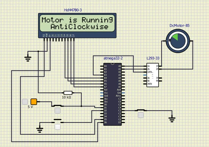
- Atmega32 IC port b D1 conneted push button through the fixed voltage source for if press the push button Motor Rotate the Anticlockwise Direction.
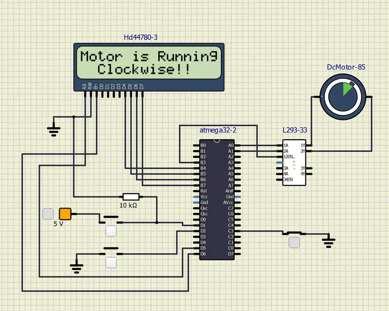
- Atmega32 IC port C C3 conneted push button through the Ground for if press the push button Motor Rotate the Clockwise Direction.
- Atmega32 D5,D6 connected to LCD Display EN and RS operation.
- EN pin-Connected to Microcontroller Pin and toggled between 1 and 0 for data acknowledgement.
- RS-Connected to Microcontroller to shift between command/data register
- RW -Used to read or write data. Normally grounded to write data to LCD
- D4-D7 - These LCD’s can also operate on 4-bit mode in such case Data pin 4,5,6 and 7 will be left free.
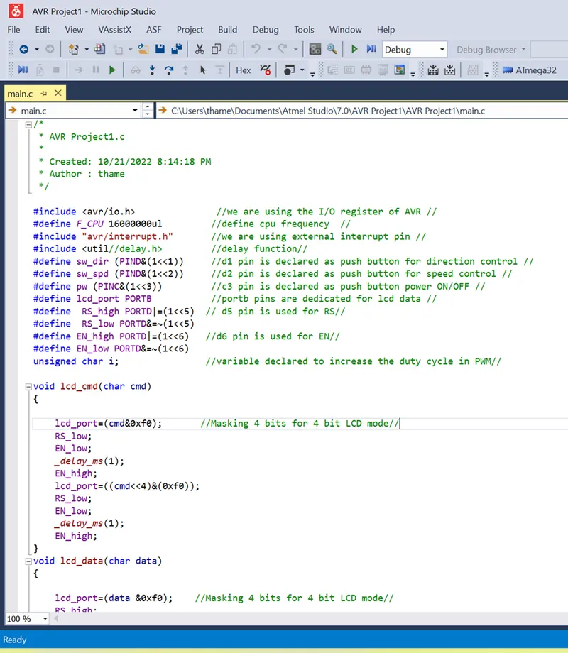
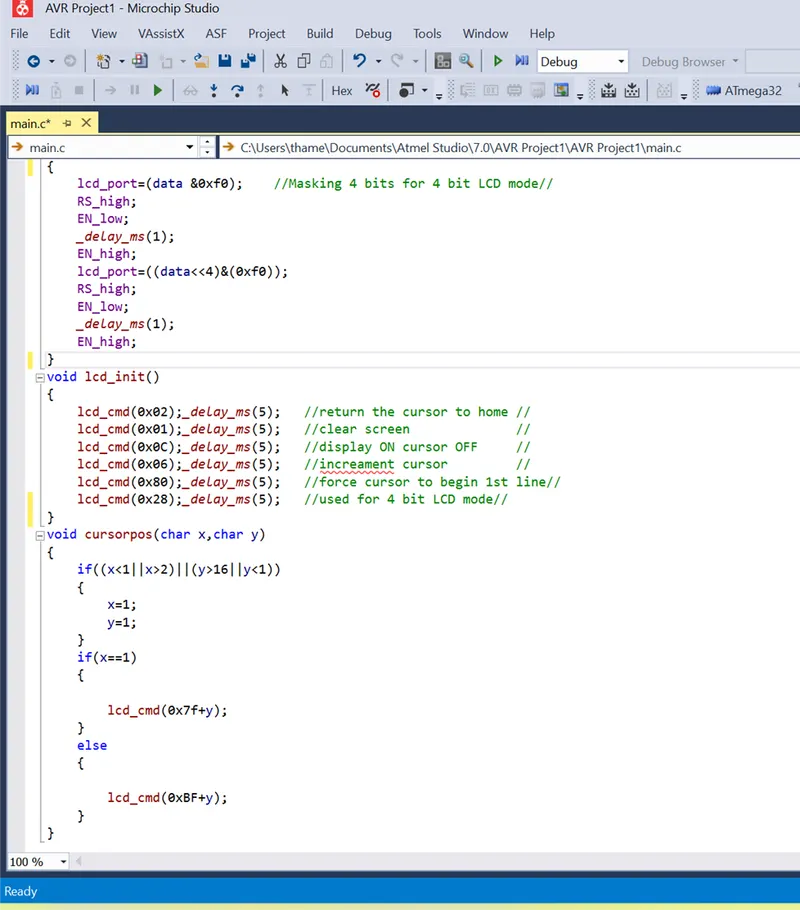
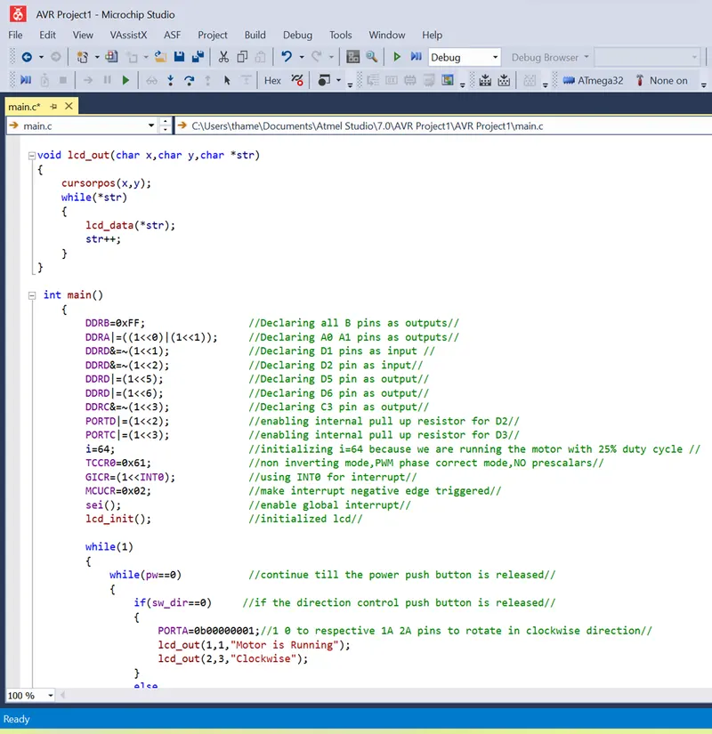
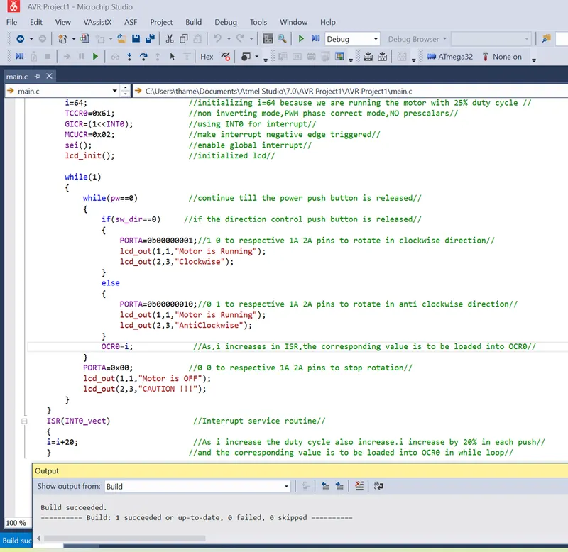
Program Code :
OUTPUT :
Deliverables of this project:
- Implement the system for controlling DC motor.
- Controlling the speed of the DC motor using PMW.
- Displaying the present running status of DC machine on LCD display.
Expected Outcomes:
- Implement a system on simulator to control a DC motor using PMW
- Monitoring the running status of the DC motor using L293 motor driver which allows the DC motor to drive on any direction.
- Running status i.e. on which direction the DC motor is running is to be displayed on the LCD screen.
"Motor is off" condition displayed in Lcd Monitor
Motor is Running Clockwise Direction shown below.Shows in LCD Display..
Motor is Running AntiClockwise Direction shown below.Shows in LCD Display..
RESULT :
The Implemented a system on the simulator for controlling a DC motor using L293 motor driver, monitor its status and printed the running status of motor Clockwise or Anticlockwisw Direction Displayed on the LCD Display .