Week - 4
- Implement control logic of a “washing machine” using Stateflow as per given sequence:
- If the power supply is available, the system gets activated
- If the Water supply is not available, stop the process & indicate through LED
- Soaking time should be 200s followed by Washing time of 100s.
- Then rinsing happens for next 20s & dryer runs for 50s
After all the processes have completed turn on the finished LED
ans:here we have to implement a control logic of a washing machine using state flow as per given sequence
first we have to take the power supply and water are the input sources if the power supply is on washing machine gets started and water supply also need in the washing process if water not available immediately stop the wwashing process by using the led we get to know that either washing proceess happemning or not power supply and water supply are the input sources to washing machine
after washing machine has some process to wash the clothes those process are soaking ,washing rinsing and drying after all these process we get to know that washing is completed and these all process are outputs like soaking washing rinsing drying these are all the outputs
we have to implement these process step by step by using the state flow diagam we have give everyb logic in a sequence manner
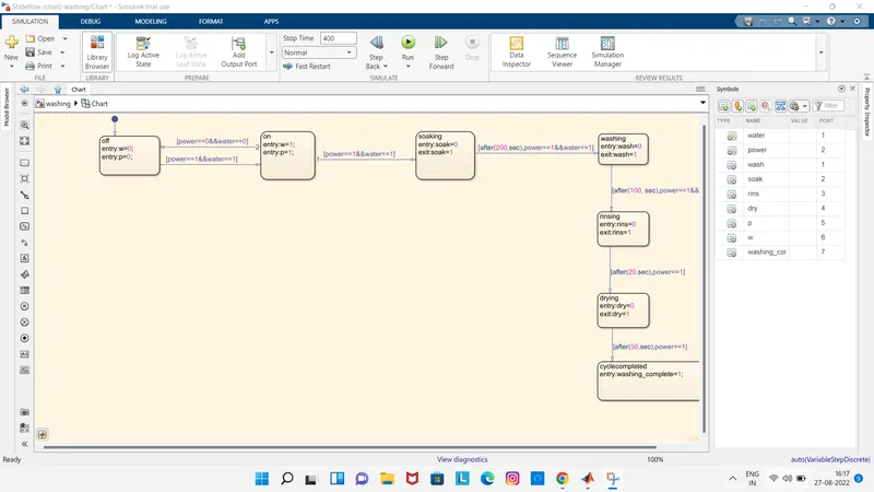
here in the above we can see that first we made a power and water is should be on to start the wasshing process if either power or water not available the process should be stop immediately
after both power and water supply is on the wasshing process starts like soaking washing drying and rinsing these processavin some delays one after one like mentioned in above
soaking takes 200seconds to finsish after soaking w3ashing process happens this take 100seconds to complete after washing rinsing process sarts it takes nearly 20seconds after that drying process happens for 50seconds we mentioned all these process step by step in the above diagram by using a state flow
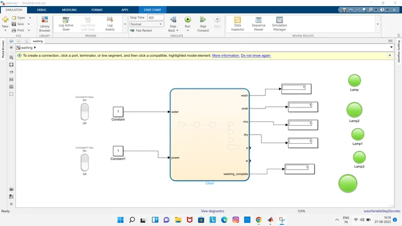
here in the above model we can see that all the leds glows green means all the processes have been completed here the power supply and water supply both on
here i used a rocketery switch and connected it to a constant value as water and i took another rocketery switch also and connected it to a constant value of power here i can control the water and power on and off conditions by using rocketery switch
and here i took the lamp in the dashboard and connected it to a display of process the lamp indicates the washing or soaking or rinsing and drying process completed or not ..here i given the green led which indicates that the process completed and i given red light which indicates the process still not completed
here in the above diagram whicgh shows that all lamps in indicates green leds whioch shows that all process are completed
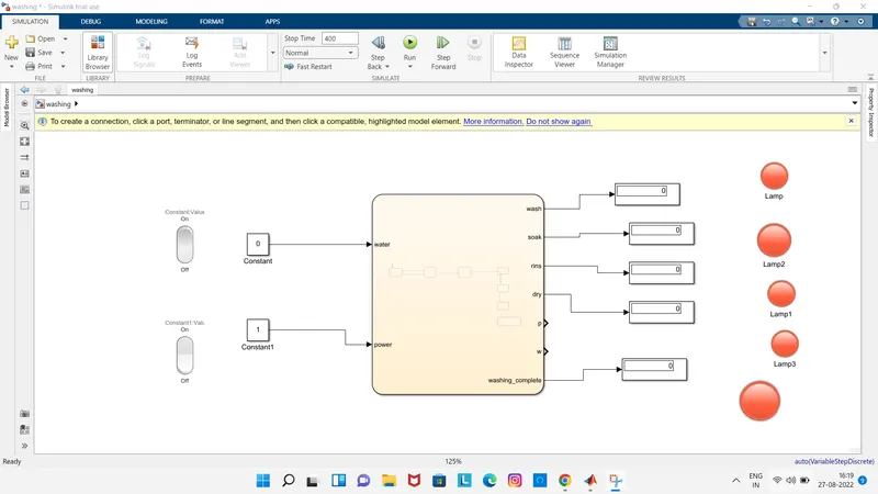
here in the above question mentioned that if water supply is off all the process should be off and we can observe in the abpove question i turned off the water supply in inputv side and we can observe that tjhe output side all lamps indicates red leds which means all tghe processes like soaking washing rinsing and drying processes still not completed
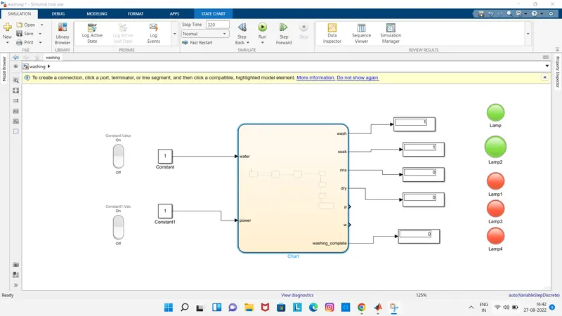
here in the above picture we can observe that washing and soaking process indicates green led which means that the wshing and soaking processes completd and remaing like rinsig and drying washing complete which indicates red led which means the riinsingb and drying processes not compled and which shows that wsshing cycle still not completed
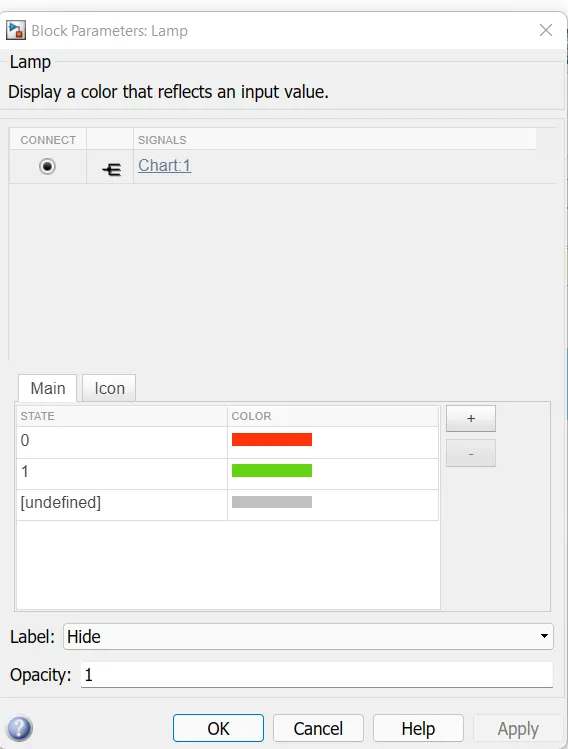
here in the above its the lamp decriptions 0 means i selected the red indication and 1 which i selected the green indication here 0 means cycle not completed and 1 which indicates that cycle completed
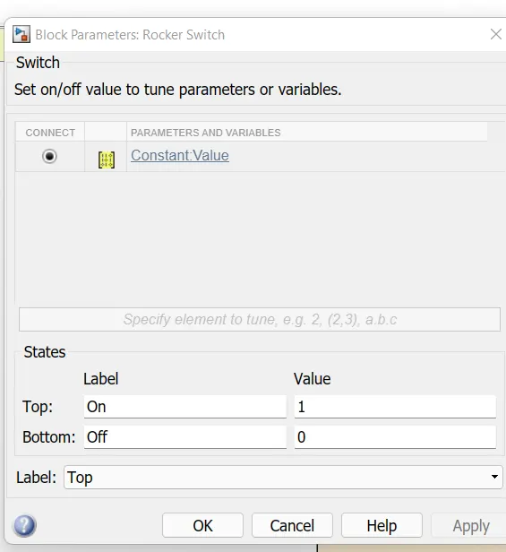
here the above picture is rocker switych description i mentioned above 1 is for on and 0 for offf
here i connected rocker switch to constant and lamp conneced to displays here by usng rocker switch we can control the inputs which is nothing but water and power means we can turn on or off the power and water supplies by using rocket switches and by using lamps we get to know that about output processes completed or not whic is nothing but soakimng washing and rinsing and drying proceeses
2. Make a Simulink chart for the “Gear shift” logic as per below conditions:
Speed Range(kmph) Gear
0 to 15 1
16 to 25 2
26 to 40 3
41 to 60 4
Above 61 5
Give speed input while the simulation is running & display the gear number.
ans: here were going to make the simulink chart for gear shift logic means at what speeed which gear were using here in the they mentioned that 5 gears and each gear having some sp[ecific speed limit
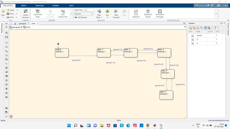
here in the above diagram wee can see that first i took a chart and opened the chart and took some blocks and gave some conditions as mentioned in the above question
first i took the block and name it as engine and give some conditions like E=1 after the engine starts we can start to accelerate after that i took the another block and named it as gear 1 and between engine and gear 1 fgiven the speed limit after that i took another block named it as gear 2 and gave some spoeed limit in between gear 1 and gear 2 in forward direction and in reverse direction also i gave some speed limit which indiates that if we shift the geears the speed also changes for exmple if i changed 1st gear to 2nd gear the speed increses and if io changed 2nd gear to first gear the speed reduces like wise i made all the blocks and given some conditions
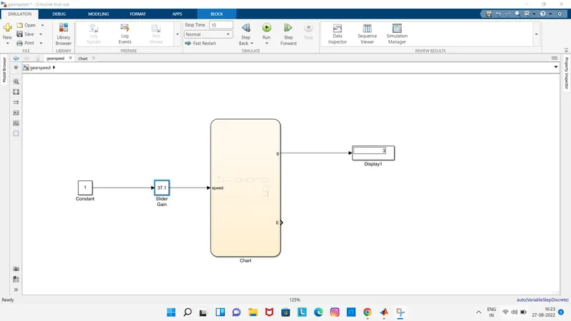
here in the above picture we can observe that the output is gear number which is conneected to display based in the speed display shows which gear were using now and we can also obnserve that we have the speed as a input and by using slider gain we changing the speed and slider gain is used when wasnty to change the values randomly because of we conneectd the speed limits forward and backward we can change the speed values randomly as we want by suing the slider gain and a constant input is given to slider gain 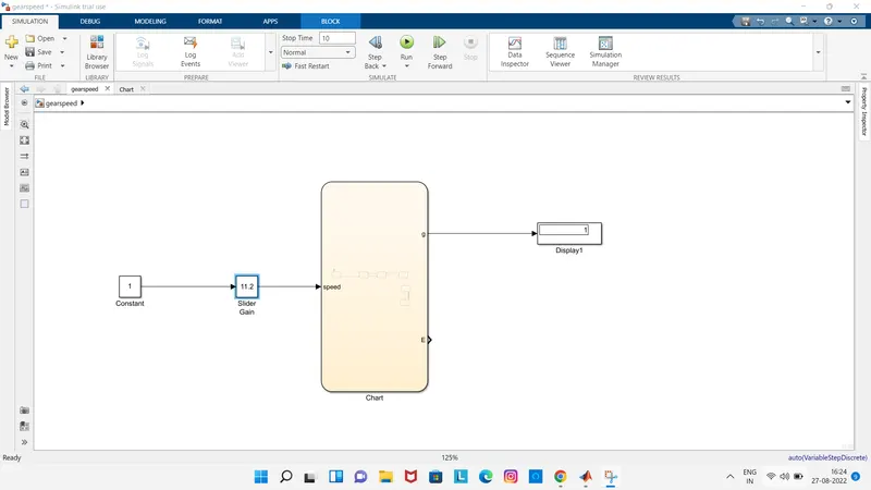
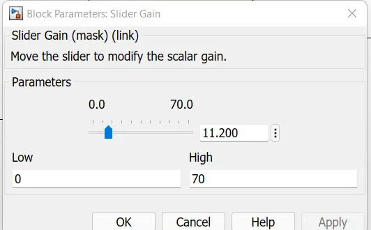
here in thje above we can see that we changed the value in the slider gain and checked in the display we could see the gear value here in the above picture i fgiven the value as 11.20 in the slider gain and i run the simulink and checked in the display it shows that gear 1
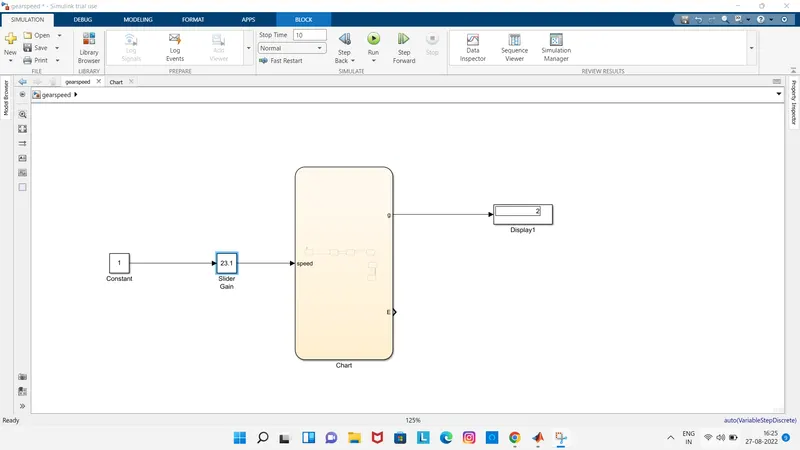
likewise previpous here in the slider gain io changed the speed value as 23.1 and run the model after i checked in display it shows that gear 2 this is how we check the gear at which speed
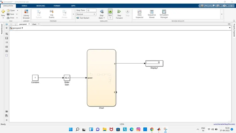
in the above picture this time i changed the maximum value to 62.3 and run the model and checked the dipsley it shows that gear 5 its the highest gear like this we can check at what speed whcih gear we are using we can give the speed as input and check the output gear value in the diasplay