Week - 4
AIM:
To implement the control logic of a washing machine using stateflow in simulink.
OBJECTIVE:
Given criteria :
if the power supply is on the system gets activated.
if the water supply is not available,stop the process and indicate to led lamp signals.
soaking time is 200 sec.
rinsing for 20 sec.
dryer foe 50 sec.
all the above process are complete led will glow.
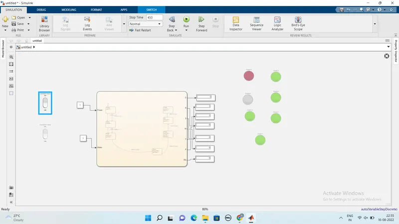
BLOCK DIAGRAM:
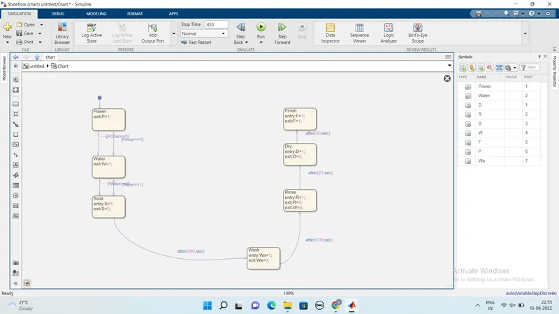
STATE FLOW:
BLOCKS USED:
rocker switch.
constant.
chart.
display.
lamp.
blocks used inside the chart.
DESCRIPTION:
power and switch inputs are controlled by switch block.these two inputs are directely connected to chart block.
state blocks were used inside the chartvto create the ststeflow according to givrn criteria.
the power input is get as input the chart and directed to the power statefrom ifpower==1(which is in on state)then the next step is goes to water block.if the power==0 then there is the power is off state.
next stsae is water if water==1 (water is in on state)then its move to next blockif water==0(it shows that water is in off state)
next to water is soaking state,after soaking then it takes 200 sec to change over from soaking to washing,after the time period of 100 sec washing is completed and next state is activated by the following chart.whgen the rinsing takes the time period of 20 sec to drying state and after 50 sec it comes to end state.
if the power is on the system gets activated,if the water is not available then the process will stop and indicate through the led lamps used in the block circuit.
power supply is given as 1 and led denotes the power is glowing green which shows the system gets activated.
when the water or power supply is 0 and the led are indicates that is no activation occurs and it will glow as red.
once the simulation starts its changes its ststes by the folowing contitions given into the chart sequentially.
RESULT:
control logic of a washing machine using state flow is implemented as per the given sequences.
AIM:
To make a simulink chart for the "gear shifter" logic for the given condition.
given contions:
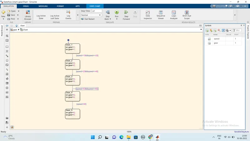
speed range(kmph) gear
0 to 15 1
16 to 25 2
26 to 40 3
41 to 60 4
above 61 5
given the speed as input while the simulation is running & display the gear number.
Blocks used:
slider.
constant.
chart.
display.
lamp.
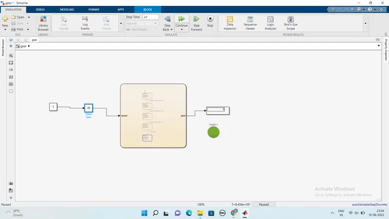
DESCRIPTION:
Using the slider block the inputs are varied by the user during the run time and is connected to the constant block.
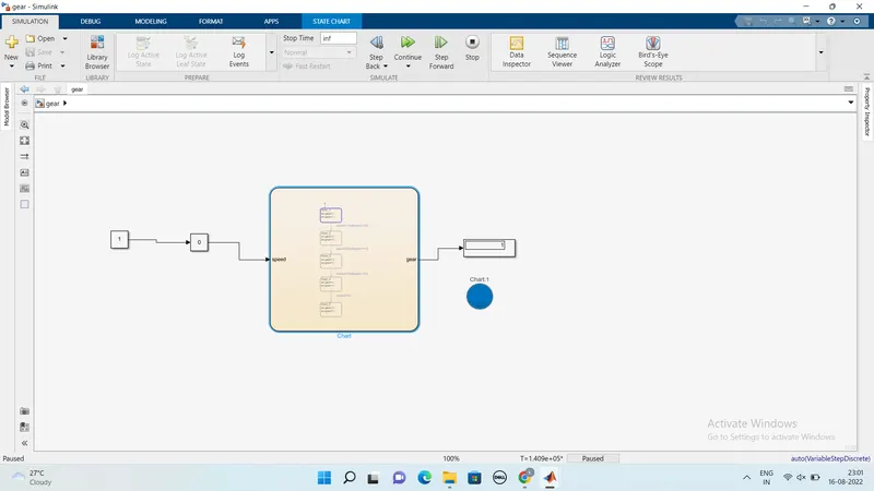
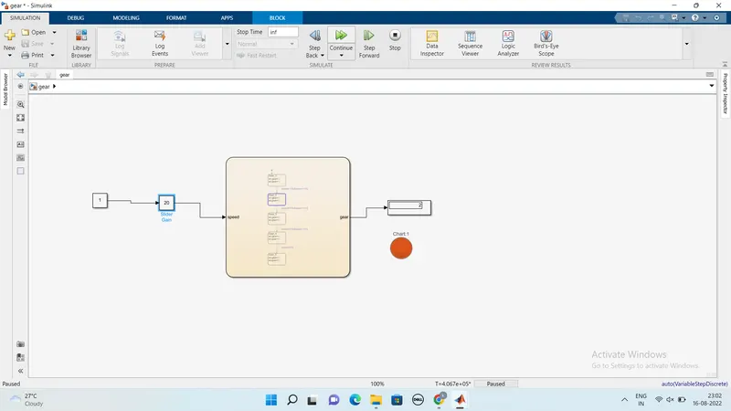
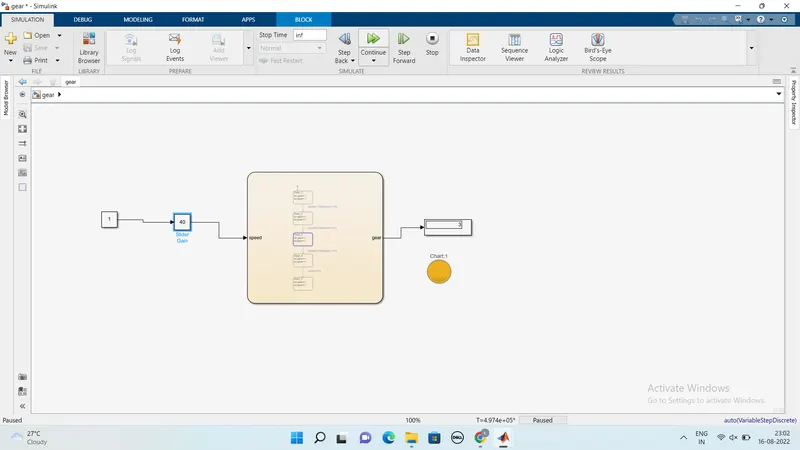
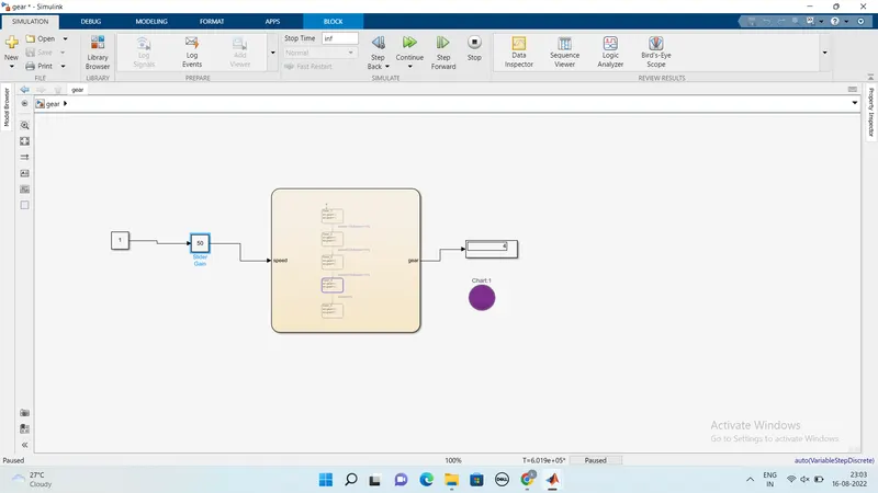
This varying the input values were given to the chart from constant block.ststes were used inside the chart to get a conditioned state flow.first the input values were given to the gear shifter block from there according to the condition,gea proceeds to the next state.when based on conditions the speed range from 0to15 the gear is engaged as 1.then the slider gain that is speed increased from 16to25 its changes from gear 1 to 2.then the speed varies from 26to40 it changes to no 3.then the soeed from 41 to 60 it change from 3 to 4.finally the speed is more than above 61 the gear is in 5 th position.it is sequentiallty increased based on the speed.
MODEL:
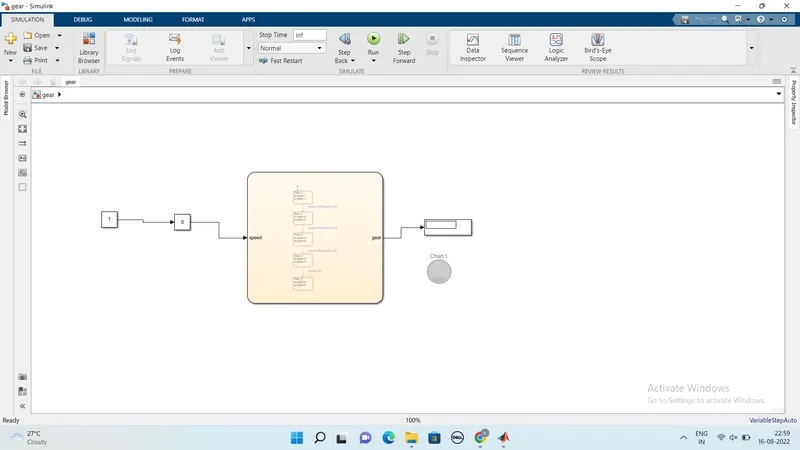
CHART:
BLOCK DIAGRAM:
GEAR1:
GEAR2:
GEAR3:
GEAR4:
GEAR5:
RESULT:
The gear shifter logic is simulated successfully for the given conditions.